EP0499208B1 - Flèche télescopique pour grues mobiles ou analogue - Google Patents
Flèche télescopique pour grues mobiles ou analogue Download PDFInfo
- Publication number
- EP0499208B1 EP0499208B1 EP92102268A EP92102268A EP0499208B1 EP 0499208 B1 EP0499208 B1 EP 0499208B1 EP 92102268 A EP92102268 A EP 92102268A EP 92102268 A EP92102268 A EP 92102268A EP 0499208 B1 EP0499208 B1 EP 0499208B1
- Authority
- EP
- European Patent Office
- Prior art keywords
- telescopic jib
- sections
- profile
- telescopic
- section
- Prior art date
- Legal status (The legal status is an assumption and is not a legal conclusion. Google has not performed a legal analysis and makes no representation as to the accuracy of the status listed.)
- Expired - Lifetime
Links
- 238000006073 displacement reaction Methods 0.000 claims 1
- 238000004519 manufacturing process Methods 0.000 abstract description 6
- 238000005452 bending Methods 0.000 description 16
- 238000010586 diagram Methods 0.000 description 5
- 230000001154 acute effect Effects 0.000 description 4
- 230000008878 coupling Effects 0.000 description 4
- 238000010168 coupling process Methods 0.000 description 4
- 238000005859 coupling reaction Methods 0.000 description 4
- 230000002349 favourable effect Effects 0.000 description 4
- 239000003351 stiffener Substances 0.000 description 4
- 239000002131 composite material Substances 0.000 description 3
- 238000010276 construction Methods 0.000 description 2
- 230000035945 sensitivity Effects 0.000 description 2
- 229910000831 Steel Inorganic materials 0.000 description 1
- 241000237983 Trochidae Species 0.000 description 1
- UQMRAFJOBWOFNS-UHFFFAOYSA-N butyl 2-(2,4-dichlorophenoxy)acetate Chemical compound CCCCOC(=O)COC1=CC=C(Cl)C=C1Cl UQMRAFJOBWOFNS-UHFFFAOYSA-N 0.000 description 1
- 230000007797 corrosion Effects 0.000 description 1
- 238000005260 corrosion Methods 0.000 description 1
- 230000007423 decrease Effects 0.000 description 1
- 230000005484 gravity Effects 0.000 description 1
- 238000012423 maintenance Methods 0.000 description 1
- 230000003068 static effect Effects 0.000 description 1
- 239000010959 steel Substances 0.000 description 1
- 239000000725 suspension Substances 0.000 description 1
- 230000007704 transition Effects 0.000 description 1
Images

Classifications
-
- B—PERFORMING OPERATIONS; TRANSPORTING
- B66—HOISTING; LIFTING; HAULING
- B66C—CRANES; LOAD-ENGAGING ELEMENTS OR DEVICES FOR CRANES, CAPSTANS, WINCHES, OR TACKLES
- B66C23/00—Cranes comprising essentially a beam, boom, or triangular structure acting as a cantilever and mounted for translatory of swinging movements in vertical or horizontal planes or a combination of such movements, e.g. jib-cranes, derricks, tower cranes
- B66C23/62—Constructional features or details
- B66C23/64—Jibs
- B66C23/70—Jibs constructed of sections adapted to be assembled to form jibs or various lengths
- B66C23/701—Jibs constructed of sections adapted to be assembled to form jibs or various lengths telescopic
- B66C23/705—Jibs constructed of sections adapted to be assembled to form jibs or various lengths telescopic telescoped by hydraulic jacks
-
- B—PERFORMING OPERATIONS; TRANSPORTING
- B66—HOISTING; LIFTING; HAULING
- B66C—CRANES; LOAD-ENGAGING ELEMENTS OR DEVICES FOR CRANES, CAPSTANS, WINCHES, OR TACKLES
- B66C23/00—Cranes comprising essentially a beam, boom, or triangular structure acting as a cantilever and mounted for translatory of swinging movements in vertical or horizontal planes or a combination of such movements, e.g. jib-cranes, derricks, tower cranes
- B66C23/62—Constructional features or details
- B66C23/64—Jibs
- B66C23/70—Jibs constructed of sections adapted to be assembled to form jibs or various lengths
- B66C23/701—Jibs constructed of sections adapted to be assembled to form jibs or various lengths telescopic
- B66C23/708—Jibs constructed of sections adapted to be assembled to form jibs or various lengths telescopic locking devices for telescopic jibs
Definitions
- the invention relates to a telescopic boom for mobile cranes, consisting of an outer link piece pivotally mounted on the vehicle or its superstructure, in which a plurality of telescopically collapsible and extendable telescopic sections are held, each section being provided with bearings for the section guided therein and with this section is lockable and a hydraulic pressure medium piston-cylinder unit is provided for extending and retracting the individual shots.
- the individual telescopic sections have a substantially box-like profile, the lower straps of the individual sections having flat V-shaped profiles or flat channel-shaped profiles that pass through from a flat one middle web part angled legs are formed. These lower belts are welded to the edge areas of the downward facing legs of U-shaped profile parts with rounded corner areas between their web parts and legs to form box-shaped profiles.
- the individual telescopic sections are mounted one inside the other on the trough-shaped lower chords according to the pressure distribution ratio known from DE-PS 21 48 966, the bearing forces being transmitted in the region of the upper rounded corners of the box profiles by rollers or appropriately shaped bearing shoes.
- bulge stiffeners with U-shaped profiles are welded onto the inside or outside of the legs of the profile.
- the lower flange which is mainly subjected to bending forces, is stiffened by its V-shape or the two longitudinal bends that form the channel shape and secured against dents.
- the known telescopic boom is not only sensitive to bulges despite the welded-in buckling stiffeners and the buckling lines, it can also be produced only with increased effort because of its complicated cross-sectional shape. Telescopic booms are not only subjected to bending, but also to torsion. In this case, the bearing elements arranged in the lower flange with a channel-shaped or V-shaped cross section counteract rotation. But if the telescopic boom is provided with a luffing needle, this is or the like via a rear A-frame.
- the object of the invention is to provide a telescopic boom of the type specified, which is characterized by a simple and economically producible construction with great bending stiffness and resistance to buckling of its individual shots.
- the articulation piece and the shots consist of profiles, each of which has a lower round and an upper half-box-shaped part in the horizontal position (pivoted onto the vehicle), the opposing legs of which are connected to one another.
- an upper semi-box-shaped profile is thus connected to a lower round profile in a horizontal parting plane.
- the lower round profile can for example be a semicircular profile.
- the lower profile part preferably has approximately the shape of a half ellipse with the apex formed by the small radius.
- the profile according to the invention thus consists of different profile parts with respect to its horizontal axis, while it is symmetrical about its vertical axis.
- the profile according to the invention meets the requirements for a telescopic boom in a particularly favorable manner.
- the profiles of the individual shots of a telescopic boom are primarily subjected to tension in their upper area and to pressure in their lower area during operation, so that the lower area is highly susceptible to buckling.
- stiffening sheets were welded into the profile on the inside and / or outside to increase the buckling stiffness.
- the profile according to the invention meets the demands of a telescopic boom in a particularly favorable manner, because the lower region, which is highly sensitive to buckling, consists of a round profile which is much less sensitive to buckling than box-shaped profiles.
- the buckling sensitivity of the lower profile part increases with the increasing compressive stress, i.e. in the direction of the lower apex line. It is therefore particularly advantageous to design the lower profile part in the form of a semi-ellipse, because this their apex region has the smallest radius of curvature and therefore has the least sensitivity to buckling in the region with the greatest compressive stress.
- the legs of the upper profile part can be at right angles to the straight web part forming the upper chord. Since the upper profile part is subjected to tension, the risk of buckling is low, so that the straight profile legs are accepted.
- the legs of the upper profile part form an obtuse angle with the straight web part. Due to this obtuse angle, the round profile part extends into the upper area of the overall profile, so that in particular the middle profile part is also less sensitive to dents.
- the lateral stress curve is highest in the middle of the profile, which increases the compressive stress in this area. If the curvature continues upwards over the center of the profile, the buckling stiffness in this area is improved.
- the legs of the upper profile part enclose acute angles with the straight web part.
- This embodiment takes into account the lateral stress curve, the corresponding risk of buckling in the lateral area, if necessary, being taken into account by appropriate measures. For example, larger sheet thicknesses can be selected or buckling stiffeners can be welded in.
- the legs of the lower round profile part connect tangentially to the straight legs of the upper profile part.
- the legs of the upper profile part are expediently connected to the straight web part by rounded regions.
- This embodiment makes it possible to arrange bearings for guiding and holding the telescopic shots in the rounded areas.
- the top shell of each shot can be folded in one piece over its entire length, so that there are no weld seams and in particular no transverse weld seams in the pull zone.
- the upper shell can be placed on a straight plate and does not need to be held in special facilities, as with a complete oval boom profile.
- the semi-box-shaped upper profile part creates additional advantages, which consist in the fact that the hoisting rope can lay down on the wide top chord without slipping sideways. Furthermore, the flat upper web part of the upper profile part is also useful for maintenance purposes, since it can be walked on safely. The upper profile part can also be sprayed with a rough covering, so that the necessary sliding security is given when walking on.
- the arrangement of the bearings in the rounded area between the upper straight web part and the legs of the upper profile part makes it possible to keep the straight side profile walls free of bearings, so that they can be painted for corrosion protection and labeled.
- all boom sections are locked to one another in the extended and retracted state and that only one pressure medium piston cylinder unit articulated at one end with the boom linkage piece of the outer shot is provided, which extends and retracts only one shot that was previously unlocked .
- This configuration ensures that the individual shots are torsionally rigidly connected to one another by their constant locking. If a lock is released for the purpose of extending and retracting a shot, these two shots are secured against rotation by this connecting pressure-piston cylinder unit, the pressure-piston cylinder unit being provided with a suitable anti-rotation device.
- an arrangement can be selected as is known from the older, but not previously published utility model G 90 13 210.6.
- the piston rod of the piston-cylinder unit can therefore be articulated on the boom link piece and a driver device for the individual shots can be arranged in the region of the end of the cylinder from which the piston rod emerges.
- a driver device for the individual shots can be arranged in the region of the end of the cylinder from which the piston rod emerges.
- only such a large length of the telescopic cylinder is buckled that corresponds to the extended part of the piston rod plus the necessary clamping length.
- the receptacles for the coupling pieces of the driver device can be arranged at the inner ends of the telescopic shots.
- the receptacles for the coupling pieces of the driver device are expediently on ring-shaped frame parts at the inner ends of the telescopic sections intended. These recordings are expediently arranged in pairs opposite one another. They can consist of holes or bushings for retractable bolts.
- the receptacles can advantageously be arranged in common planes parallel to the center line of the shots.
- bolts which can be actuated hydraulically or by compressed air and suspension are expediently provided on their collar-like thickened end regions.
- the bolts can be provided with cone-like or beveled centerings, which correct slight twists during the extension and retraction of individual shots when locking.
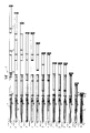
- the outer link 1 of the telescopic boom 2 is provided with a joint piece 3, by means of which it is attached to the superstructure of a crane, crane vehicle or the like. is articulated.
- the piston rod of a hydraulic piston-cylinder unit 5 is articulated in the joint 4 on the part enclosed by the outer articulation piece 1.
- a square profile 6 is articulated in a torsion-proof manner above it on the boom link piece 4.
- the articulation piece and the further telescopic shots are provided in the region of their ends with collar-like stiffeners 8-10, on which pressure medium piston cylinder units provided with locking bolts are arranged.
- the innermost telescopic shot is, as can be seen from Fig. 1, provided at its outer end with a roller head.
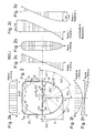
- Fig. 2 the cross section through a telescopic section or an outer link of a telescopic boom can be seen, which consists of a lower semi-elliptical profile part 40 and an upper semi-box-shaped profile part 41, the legs of which are welded together in a horizontal parting plane by welds 42, 43.
- the legs 44, 45 of the upper half-box-shaped profile part are connected to the upper web part 46 by curved regions 47, 48 with the bending radius RL.
- the lower profile part 40 is formed by a shell with a semi-elliptical cross-section, the profile shape being able to be described with a great approximation to an ellipse by the three radii ri, Rmi and Ri.
- a simplification can be made if the cross-sectional shape is defined only by the two radii ri and Rmi.
- the shape of the ellipse changes only slightly as a result of the simplifications described in the production, although from a static point of view these can even be favorable under certain circumstances. This is because the area of the bulge-resistant shell with the radius ri or the angle Ey2 becomes larger and the radius Rmi can be guided almost to the middle of the profile. This eliminates the larger and therefore less dent-proof area with the radius Ri. As a result, the lower shell 40 is overall more rigid, since the buckling security decreases linearly with the increase in the radii.
- the profile acc. Fig. 3 differs from that of FIG. 2 only in that the upper profile shell 41 'with semi-box-shaped profile legs 44' and 45 ', which include obtuse angles with the web part 46'.
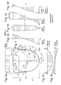
- the profile acc. Fig. 4 has an upper shell 41 "consisting of a semi-box-shaped profile, the profile legs 44" and 45 "including acute angles with the web part 46".
- the constructive middle between the dimensions H1 and H2 is the middle of the profile.
- the lower part usually has the shape of a half ellipse, which also forms the lower structural profile shell.
- the lower part can be extended upwards by dimension V, which means that dimension H2 of the upper shell is shortened accordingly.
- profile acc. Fig. 2 is the least by the uniform, lateral stress curve in the upper profile half or the upper shell, the build-up of the compressive stress in the upper bulge-sensitive side wall.
- the production of this profile is easier than that of the profiles acc. 3 and 4, since the legs 44, 45 form right angles with the web part of the upper shell, which are easier to control in steel construction because of the existing aids.
- the lateral stress curve is highest in the middle of the profile, which results in an increase in the compressive stress in this area compared to the profile according to FIG. 12.
- the radius Ri continues upward beyond the center of the profile, the buckling stiffness is thereby improved, so that this is not disadvantageous.
- the lateral stress curve has the highest value at the point at which the radius RL begins. Since the curvature by the radius R has already ended below the center of the profile, the flat profile side, which is not stiff against bulging, is larger and also shifted downwards. This area receives higher compressive stresses due to these influences. The less favorable buckling behavior may have to be compensated for by appropriate measures (larger sheet thickness or buckling strips).
Landscapes
- Engineering & Computer Science (AREA)
- Mechanical Engineering (AREA)
- Jib Cranes (AREA)
Claims (10)
Priority Applications (1)
| Application Number | Priority Date | Filing Date | Title |
|---|---|---|---|
| DE9218841U DE9218841U1 (de) | 1991-02-11 | 1992-02-11 | Teleskopausleger für Fahrzeugkrane o. dgl. |
Applications Claiming Priority (6)
| Application Number | Priority Date | Filing Date | Title |
|---|---|---|---|
| DE9101533 | 1991-02-11 | ||
| DE9101533U | 1991-02-11 | ||
| DE9102552U | 1991-03-04 | ||
| DE9102552U DE9102552U1 (de) | 1991-02-11 | 1991-03-04 | Teleskopausleger für Fahrzeugkrane o.dgl. |
| DE9113981U | 1991-11-11 | ||
| DE9113981U DE9113981U1 (de) | 1991-11-11 | 1991-11-11 | Teleskopausleger für Fahrzeugkrane o.dgl. |
Publications (4)
| Publication Number | Publication Date |
|---|---|
| EP0499208A2 EP0499208A2 (fr) | 1992-08-19 |
| EP0499208A3 EP0499208A3 (en) | 1993-05-19 |
| EP0499208B1 true EP0499208B1 (fr) | 1995-06-14 |
| EP0499208B2 EP0499208B2 (fr) | 2001-10-17 |
Family
ID=27208262
Family Applications (1)
| Application Number | Title | Priority Date | Filing Date |
|---|---|---|---|
| EP92102268A Expired - Lifetime EP0499208B2 (fr) | 1991-02-11 | 1992-02-11 | Flèche télescopique pour grues mobiles ou analogue |
Country Status (3)
| Country | Link |
|---|---|
| EP (1) | EP0499208B2 (fr) |
| AT (1) | ATE123743T1 (fr) |
| DE (1) | DE59202474D1 (fr) |
Cited By (4)
| Publication number | Priority date | Publication date | Assignee | Title |
|---|---|---|---|---|
| DE19711975A1 (de) * | 1997-03-12 | 1998-09-17 | Mannesmann Ag | Teleskopausleger für Fahrzeugkrane |
| US6978907B2 (en) | 2001-12-12 | 2005-12-27 | Grove U.S. Llc | Telescopic jib for a vehicular crane |
| JP2006021877A (ja) * | 2004-07-08 | 2006-01-26 | Tadano Ltd | 伸縮ブーム |
| WO2017065066A1 (fr) * | 2015-10-13 | 2017-04-20 | 株式会社タダノ | Flèche de machine de travail |
Families Citing this family (6)
| Publication number | Priority date | Publication date | Assignee | Title |
|---|---|---|---|---|
| DE4344795A1 (de) * | 1993-12-28 | 1995-06-29 | Liebherr Werk Ehingen | Fahrbarer Kran mit einem Teleskopausleger |
| DE19624312C2 (de) * | 1996-06-18 | 2000-05-31 | Grove Us Llc | Teleskopausleger für Fahrzeugkrane |
| DE19811813B4 (de) * | 1998-03-18 | 2005-11-24 | Grove U.S. LLC (n.d.Ges.d.Staates Delaware) | Seitliche Auslegerverriegelung |
| US6499612B1 (en) | 2001-07-27 | 2002-12-31 | Link-Belt Construction Equipment Co., L.P., Lllp | Telescoping boom assembly with rounded profile sections and interchangeable wear pads |
| DE102006014573B3 (de) * | 2006-03-29 | 2007-07-19 | Manitowoc Crane Group France SAS, | Teleskopkran-Auslegerteil mit schwächer und stärker gekrümmten Querschnittssegmenten im oberen Profilteil und im unteren Profilteil |
| JP2010089919A (ja) | 2008-01-09 | 2010-04-22 | Kobelco Cranes Co Ltd | 伸縮ブーム |
Family Cites Families (12)
| Publication number | Priority date | Publication date | Assignee | Title |
|---|---|---|---|---|
| FR1279493A (fr) * | 1960-11-10 | 1961-12-22 | Grue perfectionnée | |
| DE1170134B (de) * | 1962-05-11 | 1964-05-14 | Focke Wulf Ges Mit Beschraenkt | Hoehenverstellbare Arbeitsbuehne |
| US3250182A (en) * | 1963-08-01 | 1966-05-10 | Harold K Nansel | Multiple extension apparatus |
| FR1415329A (fr) * | 1964-12-01 | 1965-10-22 | Ver Flugtechnische Werke | Plate-forme de travail réglable en hauteur |
| DE2148966C3 (de) * | 1971-09-30 | 1978-11-23 | Liebherr-Werk Ehingen Gmbh, 7930 Ehingen | Teleskopausleger, insbesondere für straßenverfahrbare Krane |
| US3842985A (en) * | 1972-12-15 | 1974-10-22 | Harnischfeger Corp | Means for extending and retracting crane boom section |
| US4588347A (en) * | 1981-10-02 | 1986-05-13 | Coles Cranes Limited | Telescopic booms |
| DE3216427A1 (de) * | 1982-05-03 | 1983-11-10 | Heinrich H. Klüssendorf GmbH & Co KG, 1000 Berlin | Einrichtung zur fuehrung zweier axial ineinander beweglicher stangen- oder/und roehrenartiger elemente |
| SE456820B (sv) * | 1984-03-12 | 1988-11-07 | Oesa Ab | Anordning vid teleskoparmar |
| DE3510710A1 (de) * | 1985-03-23 | 1986-10-02 | Fried. Krupp Gmbh, 4300 Essen | Teleskopkran |
| US4688690A (en) * | 1986-03-07 | 1987-08-25 | Harnischfeger Corporation | Method and apparatus for extending fly section of crane boom |
| DE9013210U1 (de) * | 1990-09-18 | 1991-01-03 | Liebherr-Werk Ehingen Gmbh, 7930 Ehingen | Teleskopiersystem mit verringerter Knicklänge des Teleskopierzylinders |
-
1992
- 1992-02-11 AT AT92102268T patent/ATE123743T1/de not_active IP Right Cessation
- 1992-02-11 DE DE59202474T patent/DE59202474D1/de not_active Expired - Lifetime
- 1992-02-11 EP EP92102268A patent/EP0499208B2/fr not_active Expired - Lifetime
Cited By (5)
| Publication number | Priority date | Publication date | Assignee | Title |
|---|---|---|---|---|
| DE19711975A1 (de) * | 1997-03-12 | 1998-09-17 | Mannesmann Ag | Teleskopausleger für Fahrzeugkrane |
| DE19711975B4 (de) * | 1997-03-12 | 2006-09-07 | Terex-Demag Gmbh & Co. Kg | Teleskopausleger für Fahrzeugkrane |
| US6978907B2 (en) | 2001-12-12 | 2005-12-27 | Grove U.S. Llc | Telescopic jib for a vehicular crane |
| JP2006021877A (ja) * | 2004-07-08 | 2006-01-26 | Tadano Ltd | 伸縮ブーム |
| WO2017065066A1 (fr) * | 2015-10-13 | 2017-04-20 | 株式会社タダノ | Flèche de machine de travail |
Also Published As
| Publication number | Publication date |
|---|---|
| ATE123743T1 (de) | 1995-06-15 |
| EP0499208B2 (fr) | 2001-10-17 |
| EP0499208A2 (fr) | 1992-08-19 |
| DE59202474D1 (de) | 1995-07-20 |
| EP0499208A3 (en) | 1993-05-19 |
Similar Documents
| Publication | Publication Date | Title |
|---|---|---|
| EP1935833B1 (fr) | Elément de grille pour une grande grue mobile et son procédé de montage | |
| DE69733860T2 (de) | Teleskopausleger für Fahrzeugkrane | |
| DE3116239A1 (de) | Hohler kranausleger-abschnitt | |
| EP2998264B1 (fr) | Mât en treillis haubanés latéralement | |
| DE2460697A1 (de) | Teleskopausleger fuer krane | |
| EP0583552B1 (fr) | Flêche télescopique pour grues mobiles ou analogues | |
| DE1281651B (de) | Teleskopartig ein- und ausfahrbarer kranausleger | |
| DE1556861A1 (de) | Ausfahrbarer Arm,Mast oder aehnliche Anordnung | |
| EP0499208B1 (fr) | Flèche télescopique pour grues mobiles ou analogue | |
| DE19948830B4 (de) | Teleskopausleger für Krane | |
| DE102015006117A1 (de) | Verfahren zum Betrieb eines Krans und Kran | |
| DE1531146B2 (de) | Hydraulischer antrieb fuer einen kranausleger mit teleskopartig verschiebbaren auslegerstuecken | |
| DE102009018689A1 (de) | Auslegerelement für ein Hebezeug | |
| DE2944289A1 (de) | Hebefahrzeug | |
| DE2040687A1 (de) | Teleskopartig ein- und ausfahrbarer Kranausleger mit kastenfoermigen Auslegerteilen | |
| EP1321425A1 (fr) | Flèche télescopique pour grue mobile | |
| DE3015599A1 (de) | Teleskopierbarer kranausleger | |
| AT524350B1 (de) | Fahrzeugkran mit einem Auslegersystem | |
| DE3340845C1 (de) | Gittermastkran mit zerlegbarem Hauptausleger | |
| EP3184478B1 (fr) | Grue | |
| DE102020134714B4 (de) | Fahrzeugkran mit einem wippbaren Hauptausleger und mit einem Zusatzauslegersystem | |
| DE4109052A1 (de) | Leichtbauprofil | |
| DE9113981U1 (de) | Teleskopausleger für Fahrzeugkrane o.dgl. | |
| DD215518A5 (de) | Ausleger fuer hebezeuge, insbesondere hebebuehnen, bagger oder dergleichen | |
| DE102017128176A1 (de) | Mastsegment eines Knickmastes mit Kröpfung |
Legal Events
| Date | Code | Title | Description |
|---|---|---|---|
| PUAI | Public reference made under article 153(3) epc to a published international application that has entered the european phase |
Free format text: ORIGINAL CODE: 0009012 |
|
| AK | Designated contracting states |
Kind code of ref document: A2 Designated state(s): AT DE FR GB IT NL |
|
| PUAL | Search report despatched |
Free format text: ORIGINAL CODE: 0009013 |
|
| AK | Designated contracting states |
Kind code of ref document: A3 Designated state(s): AT DE FR GB IT NL |
|
| 17P | Request for examination filed |
Effective date: 19930602 |
|
| 17Q | First examination report despatched |
Effective date: 19941011 |
|
| GRAA | (expected) grant |
Free format text: ORIGINAL CODE: 0009210 |
|
| AK | Designated contracting states |
Kind code of ref document: B1 Designated state(s): AT DE FR GB IT NL |
|
| PG25 | Lapsed in a contracting state [announced via postgrant information from national office to epo] |
Ref country code: NL Free format text: LAPSE BECAUSE OF FAILURE TO SUBMIT A TRANSLATION OF THE DESCRIPTION OR TO PAY THE FEE WITHIN THE PRESCRIBED TIME-LIMIT Effective date: 19950614 |
|
| REF | Corresponds to: |
Ref document number: 123743 Country of ref document: AT Date of ref document: 19950615 Kind code of ref document: T |
|
| ITF | It: translation for a ep patent filed | ||
| GBT | Gb: translation of ep patent filed (gb section 77(6)(a)/1977) |
Effective date: 19950612 |
|
| REF | Corresponds to: |
Ref document number: 59202474 Country of ref document: DE Date of ref document: 19950720 |
|
| PLBI | Opposition filed |
Free format text: ORIGINAL CODE: 0009260 |
|
| 26 | Opposition filed |
Opponent name: PROF. KARL WEBER AM BACH Effective date: 19950731 |
|
| ET | Fr: translation filed | ||
| NLR1 | Nl: opposition has been filed with the epo |
Opponent name: PROF. KARL WEBER AM BACH |
|
| PLBQ | Unpublished change to opponent data |
Free format text: ORIGINAL CODE: EPIDOS OPPO |
|
| PLBQ | Unpublished change to opponent data |
Free format text: ORIGINAL CODE: EPIDOS OPPO |
|
| PLBI | Opposition filed |
Free format text: ORIGINAL CODE: 0009260 |
|
| PLBF | Reply of patent proprietor to notice(s) of opposition |
Free format text: ORIGINAL CODE: EPIDOS OBSO |
|
| 26 | Opposition filed |
Opponent name: MANNESMANN AG Effective date: 19960314 Opponent name: EC ENGINEERING + CONSULTING SPEZIALMASCHINEN GMBH Effective date: 19960314 Opponent name: PROF. KARL WEBER AM BACH Effective date: 19950731 |
|
| NLR1 | Nl: opposition has been filed with the epo |
Opponent name: MANNESMANN AG Opponent name: EC ENGINEERING Opponent name: PROF. KARL WEBER AM BACH Opponent name: CONSULTING SPEZIALMASCHINEN GMBH |
|
| PLBF | Reply of patent proprietor to notice(s) of opposition |
Free format text: ORIGINAL CODE: EPIDOS OBSO |
|
| PLBO | Opposition rejected |
Free format text: ORIGINAL CODE: EPIDOS REJO |
|
| PLBO | Opposition rejected |
Free format text: ORIGINAL CODE: EPIDOS REJO |
|
| APAC | Appeal dossier modified |
Free format text: ORIGINAL CODE: EPIDOS NOAPO |
|
| APAE | Appeal reference modified |
Free format text: ORIGINAL CODE: EPIDOS REFNO |
|
| APAC | Appeal dossier modified |
Free format text: ORIGINAL CODE: EPIDOS NOAPO |
|
| PGFP | Annual fee paid to national office [announced via postgrant information from national office to epo] |
Ref country code: NL Payment date: 20010227 Year of fee payment: 10 |
|
| APAC | Appeal dossier modified |
Free format text: ORIGINAL CODE: EPIDOS NOAPO |
|
| PLAW | Interlocutory decision in opposition |
Free format text: ORIGINAL CODE: EPIDOS IDOP |
|
| PUAH | Patent maintained in amended form |
Free format text: ORIGINAL CODE: 0009272 |
|
| STAA | Information on the status of an ep patent application or granted ep patent |
Free format text: STATUS: PATENT MAINTAINED AS AMENDED |
|
| 27A | Patent maintained in amended form |
Effective date: 20011017 |
|
| AK | Designated contracting states |
Kind code of ref document: B2 Designated state(s): AT DE FR GB IT NL |
|
| NLR2 | Nl: decision of opposition | ||
| REG | Reference to a national code |
Ref country code: GB Ref legal event code: IF02 |
|
| GBTA | Gb: translation of amended ep patent filed (gb section 77(6)(b)/1977) | ||
| ET3 | Fr: translation filed ** decision concerning opposition | ||
| NLV1 | Nl: lapsed or annulled due to failure to fulfill the requirements of art. 29p and 29m of the patents act | ||
| PGFP | Annual fee paid to national office [announced via postgrant information from national office to epo] |
Ref country code: AT Payment date: 20050218 Year of fee payment: 14 |
|
| APAH | Appeal reference modified |
Free format text: ORIGINAL CODE: EPIDOSCREFNO |
|
| PG25 | Lapsed in a contracting state [announced via postgrant information from national office to epo] |
Ref country code: AT Free format text: LAPSE BECAUSE OF NON-PAYMENT OF DUE FEES Effective date: 20060211 |
|
| PGFP | Annual fee paid to national office [announced via postgrant information from national office to epo] |
Ref country code: GB Payment date: 20100217 Year of fee payment: 19 |
|
| PGFP | Annual fee paid to national office [announced via postgrant information from national office to epo] |
Ref country code: FR Payment date: 20110307 Year of fee payment: 20 Ref country code: IT Payment date: 20110221 Year of fee payment: 20 Ref country code: DE Payment date: 20110315 Year of fee payment: 20 |
|
| GBPC | Gb: european patent ceased through non-payment of renewal fee |
Effective date: 20110211 |
|
| REG | Reference to a national code |
Ref country code: DE Ref legal event code: R071 Ref document number: 59202474 Country of ref document: DE |
|
| REG | Reference to a national code |
Ref country code: DE Ref legal event code: R071 Ref document number: 59202474 Country of ref document: DE |
|
| PG25 | Lapsed in a contracting state [announced via postgrant information from national office to epo] |
Ref country code: GB Free format text: LAPSE BECAUSE OF NON-PAYMENT OF DUE FEES Effective date: 20110211 |
|
| PG25 | Lapsed in a contracting state [announced via postgrant information from national office to epo] |
Ref country code: DE Free format text: LAPSE BECAUSE OF EXPIRATION OF PROTECTION Effective date: 20120212 |