EP0484562A1 - Vorrichtung zum wechseln von tauchdüsen - Google Patents
Vorrichtung zum wechseln von tauchdüsen Download PDFInfo
- Publication number
- EP0484562A1 EP0484562A1 EP91920976A EP91920976A EP0484562A1 EP 0484562 A1 EP0484562 A1 EP 0484562A1 EP 91920976 A EP91920976 A EP 91920976A EP 91920976 A EP91920976 A EP 91920976A EP 0484562 A1 EP0484562 A1 EP 0484562A1
- Authority
- EP
- European Patent Office
- Prior art keywords
- immersion nozzle
- nozzle
- terminal
- molten metal
- exchanging apparatus
- Prior art date
- Legal status (The legal status is an assumption and is not a legal conclusion. Google has not performed a legal analysis and makes no representation as to the accuracy of the status listed.)
- Granted
Links
Images


Classifications
-
- B—PERFORMING OPERATIONS; TRANSPORTING
- B22—CASTING; POWDER METALLURGY
- B22D—CASTING OF METALS; CASTING OF OTHER SUBSTANCES BY THE SAME PROCESSES OR DEVICES
- B22D41/00—Casting melt-holding vessels, e.g. ladles, tundishes, cups or the like
- B22D41/50—Pouring-nozzles
- B22D41/56—Means for supporting, manipulating or changing a pouring-nozzle
-
- B—PERFORMING OPERATIONS; TRANSPORTING
- B22—CASTING; POWDER METALLURGY
- B22D—CASTING OF METALS; CASTING OF OTHER SUBSTANCES BY THE SAME PROCESSES OR DEVICES
- B22D11/00—Continuous casting of metals, i.e. casting in indefinite lengths
- B22D11/10—Supplying or treating molten metal
Definitions
- This invention relates to an immersion nozzle exchanging apparatus for attachment and detachment of an immersion nozzle to be used in casting a molten metal from a molten metal container such as a tundish.
- the immersion nozzle exchanging apparatus of this kind is disclosed in Japanese Utility Model Publication SHO 57(1982)-54,919.
- the immersion nozzle exchanging apparatus of this patent specification is constructed by setting a vertically operable cylinder on a supporting member fixed on the lateral wall or the bottom of a tundish or in a slide gate valve equipment, for example, attaching an item of hardware to the leading terminal of a piston rod of the cylinder in such a manner as to be freely rotated in the horizontal direction, interlocking a supporting arm slidably and rotatably to the hardware, and providing immersion nozzle fixtures one each at the opposite terminal parts of the supporting arm.
- the conventional immersion nozzle exchanging apparatus is fixed to a tundish or a slide gate valve equipment, the attchment or detachment of an immersion nozzle to or from the immersion nozzle exchanging apparatus requires a worker to approach the tundish and work in a hot atmosphere. The safety of this work, therefore, is extremely dubious.
- the apparatus also has a fault in respect that the immersion nozzle is deficient in the ability to allow close adhesion thereto of a molten metal because a jointing material such as mortar or packings and metal adhering to the outlet nozzle of the tundish defy removal.
- the immersion nozzle exchanging apparatus which preferably embodies this invention is provided at the leading terminal of the movable arm with a first retainer part for retaining a used immersion nozzle and a second retainer part for retaining an immersion nozzle to be attached to the lower terminal of the outlet nozzle.
- the immersion nozzle exchanging apparatus which preferably embodies this invention is provided at the leading terminal of the movable arm with a block so as to be extended in a horizontal direction perpendicular to the longitudinal direction of the movable arm, with the first retainer part disposed on one terminal side in the extended direction of the block and the second retainer part disposed on the other terminal side thereof.
- the immersion nozzle exchanging apparatus which preferably embodies this invention is provided with the cleaning device in the medial part of the block relative to the extended direction thereof.
- the first retainer part which is used in the immersion nozzle exchanging apparatus which preferably embodies this invention comprises a pair of plates and grooves formed one each in the upper surfaces of the plates.
- the first retainer part which is used in the immersion nozzle exchanging apparatus which preferably embodies this invention is provided with a pair of forks which are each provided in the leading terminal part thereof with a slanted surface intended to form an inclination in the direction of the basal terminal thereof and in the basal terminal part thereof with a horizontal surface.
- the work of exchanging an immersion nozzle enjoys high safety and permits labor saving because this work can be performed with the art at a position separated from the tundish.
- the immersion nozzle has the close adhesiveness or sealing property thereof improved because the cleaning device is capable of removing the jointing material such as mortar or packings and the metal from the lower terminal surface of the outlet nozzle on the tundish side.
- Fig. 1 is an overall plan view illustrating an apparatus embodying this invention.
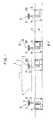
- Fig. 2A is a cross section taken through Fig. 1 across the line II-II.
- Fig. 2B is a magnified diagram of the essential part of the cross section of Fig. 2A.
- Fig. 3 is a perspective view of the leading terminal part of an arm.
- Fig. 4 is a perspective view of the upper part of an immersion nozzle.
- Fig. 5 is a cross section taken through Fig. 2B along the line V-V.
- an immersion nozzle 3 is attached to and detached from the lower terminal of an outlet nozzle 2 of a tundish 1.
- Rails 4 are laid so as to approximate closely to the outlet nozzle 2 of the tundish 1.
- a self-propelling truck 5 is set on the rails so as to travel between a retracting position A and an immersion nozzle exchanging position C.
- This self-propelling truck 5 is provided with a movable arm 6 disposed in a lateral direction perpendicular to the direction of travel of the self-propelling truck 5.
- the movable arm 6 is provided at the leading terminal thereof with a block 7 for supporting the immersion nozzle 3, a cleaning device 18 for cleaning the lower terminal surface of the outlet nozzle 2, etc.
- the arm 6 is capable of freely advancing, retracting, fanning, and tilting and further capable of being vertically reciprocated by means of a cylinder (not shown).
- the arm 6 is provided at the leading terminal thereof with the block 7 which is disposed so as to extend in a horizontal direction perpendicular to the longitudinal direction of the arm 6.
- the block 7 is provided at one terminal side in the longitudinal direction thereof with a pair of plates 8, 9 having vertical surfaces and extending in a direction perpendicular to the extending direction of the arm 6.
- immersion nozzle retainer parts severally furnished with grooves 10, 11.
- a pair of forks 12, 13 are extended from the block 7.
- These forks 12, 13 are provided with immersion nozzle retaining parts incorporating respectively therein slanted surfaces 14, 15 (the slanted surface 14 not shown in Fig. 3) inclined upwardly in the direction of block 7 and horizontal parts 16, 17 (the horizontal part 16 not shown in Fig. 3).
- a cleaning device 18 provided with a rotary wire brush or a sharpening stone having the axis of rotation in the vertical direction and adapted to clean the lower terminal surface of the outlet nozzle is installed.
- the immersion nozzle 3, as illustrated in Fig. 4, is provided on the upper terminal thereof with a holder 3a from which pins 19, 20 are projected in a diametric direction.
- the immersion nozzle 3 is retained in the leading terminal part of the arm 6 in such a manner that the pins 19, 20 lie astraddle the grooves 10, 11 or the horizontal parts 16, 17.
- Denoted by 21 is a packing.
- Figs. 2A and 2B 22 stands for a mold.
- a lower nozzle (immersion nozzle) fixing cylinder device 50 as disclosed in Japanese Utility Model Publciation SHO 63(1988)-31819 titled "Lower nozzle fixing device for molten metal container” is seated.
- a support 23 is extended from the cylinder device 50 to a level below the outlet nozzle 2. This support 23 is vertically reciprocated by the cylinder device 50.
- the support 23 is provided with a depressed part 24 in which the pins 19, 20 of the immersion nozzle 3 are set.
- the immersion nozzle 3 is supported by the support 23 by the fact that the pins 19, 20 thereof are hooked in the depressed part 24.
- the joining of the immersion nozzle 3 with the outlet nozzle 2 is attained by the pulling of the support 23 by the cylinder device 50.
- the self-propelling truck is located at the retracting position A shown in Fig. 1, where a used immersion nozzle 3 taken out of the tundish 1 is extracted. Then, the self-propelling truck is moved to the waiting position B, where it is loaded with an immersion nozzle 3 to be newly attached to the tundish 1 and then kept waiting.
- the extraction of the used immersion nozzle 33 from the tundish 1 requires the tundish 1 to be elevated to a height at which the used immersion nozzle 33 avoids colliding against the upper surface of the cover for the mold 22.
- the immersion nozzle fixing cylinder device 50 is set into motion to move the used immersion nozzle 33 downwardly from the set position (the position at which the union with the outlet nozzle 2 is formed) to break the union.
- the block 7 of the immersion nozzle exchanging apparatus is moved closely to the support 23 of the immersion nozzle fixing cylinder device of the mold 22. Then, the worker sets the packing 21 on the immersion nozzle 3 newly supplied as supported on the block 7.
- the arm 6 is moved so that the slanted surfaces 14, 15 of the forks 12, 13 may be interlocked with the pins 19, 20 of the used immersion nozzle 33 supported by the support 23.
- the used immersion nozzle 33 supported by the support 23 is lifted and liberated from the support 23.
- the extraction of the used immersion nozzle 33 is attained by retracting the arm 6 from under the outlet nozzle 2.
- the cleaning of the lower terminal surface of the outlet nozzle 2 is effected by causing the rotary wire brush or sharpening stone 18 to be placed below the outlet nozzle 2, pressing the rotary wire brush or sharpening stone 18 against the lower terminal surface of the output nozzle 2, and setting it into rotation.
- the setting of the newly supplied immersion nozzle 3 is accomplished by moving the newly supplied immersion nozzle 3 retained dangllingly by the grooves 10, 11 of the plates 8, 9 to the nozzle center position of the outlet nozzle 2 and allowing the pins 19, 20 to be hooked by the support 23.
- the immersion nozzle fixing cylinder device 50 is put to operation and, as a result, the support 23 is moved upwardly and the immersion nozzle 3 is joined to the lower terminal of the outlet nozzle 2 and immobilized there.
- the attachment and detachment of the immersion nozzles 3, 33 to and from the leading terminal part of the arm 6 can be carried out under remote control.
- This work of exchanging the immersion nozzles 3, 33 therefore, enjoys high safety and permits labor saving unlike the work which is performed near the mold.
- the rotary wire brush or sharpening stone 18 cleans the lower terminal surface of the outlet nozzle 2, close mutual adhesion is established between the outlet nozzle 2 and the immersion nozzle 3 and the casting can be carried out in a mold of high sealing property.
- the immersion nozzle exchanging apparatus of this invention since the work of exchanging the immersion nozzles relative to the tundish can be carried out substantially automatically as described above, the work enjoys ideal operational efficiency and permits labor saving and the work in a hot atmosphere similarly enjoys very high safety. Moreover, in the apparatus of this invention, since the mutual adhesion of the outlet nozzle and the immersion nozzle is attained with conspicuously improved closeness, the mold defies leakage of air and the cast metallic article consequently acquires improved quality.
Landscapes
- Engineering & Computer Science (AREA)
- Mechanical Engineering (AREA)
- Casting Support Devices, Ladles, And Melt Control Thereby (AREA)
- Continuous Casting (AREA)
- Furnace Housings, Linings, Walls, And Ceilings (AREA)
- Jet Pumps And Other Pumps (AREA)
Applications Claiming Priority (3)
| Application Number | Priority Date | Filing Date | Title |
|---|---|---|---|
| JP133234/90 | 1990-05-23 | ||
| JP2133234A JP2870986B2 (ja) | 1990-05-23 | 1990-05-23 | 浸漬ノズル交換装置 |
| PCT/JP1991/000634 WO1991017851A1 (en) | 1990-05-23 | 1991-05-14 | Device for replacing immersed nozzles |
Publications (3)
| Publication Number | Publication Date |
|---|---|
| EP0484562A1 true EP0484562A1 (de) | 1992-05-13 |
| EP0484562A4 EP0484562A4 (en) | 1992-12-09 |
| EP0484562B1 EP0484562B1 (de) | 1996-02-28 |
Family
ID=15099850
Family Applications (1)
| Application Number | Title | Priority Date | Filing Date |
|---|---|---|---|
| EP91920976A Expired - Lifetime EP0484562B1 (de) | 1990-05-23 | 1991-05-14 | Vorrichtung zum wechseln von tauchdüsen |
Country Status (8)
| Country | Link |
|---|---|
| US (1) | US5238158A (de) |
| EP (1) | EP0484562B1 (de) |
| JP (1) | JP2870986B2 (de) |
| KR (1) | KR960003720B1 (de) |
| AT (1) | ATE134544T1 (de) |
| AU (1) | AU641503B2 (de) |
| DE (1) | DE69117436T2 (de) |
| WO (1) | WO1991017851A1 (de) |
Cited By (3)
| Publication number | Priority date | Publication date | Assignee | Title |
|---|---|---|---|---|
| FR2721845A1 (fr) * | 1994-06-30 | 1996-01-05 | Lorraine Laminage | Dispositifs de mise en place d'un tube de protection de jet sur un recipient matallurgique |
| EP0858851A1 (de) * | 1997-01-17 | 1998-08-19 | Sumitomo Heavy Industries, Ltd. | Brammen-Stranggiessmaschine mit Vorrichtung zum Auswechseln eines Tauchgiessrohres und Verfahren zum Auswechseln eines Tauchgiessrohres |
| AT408077B (de) * | 1992-08-25 | 2001-08-27 | Ferro Montagetechnik Ges M B H | Manipulator zum ansetzen eines giessrohres an den ausgussschieber einer giesspfanne |
Families Citing this family (3)
| Publication number | Priority date | Publication date | Assignee | Title |
|---|---|---|---|---|
| WO1995030501A1 (fr) * | 1994-05-06 | 1995-11-16 | Shinagawa Shirorenga Kabushiki Kaisha | Dispositif de remplacement pour buses a immersion |
| EP1541487A1 (de) * | 2002-07-31 | 2005-06-15 | Otsuka Pharmaceutical Co., Ltd. | ABF HRGLIED UND DAMIT VERSEHENER BEHûLTER |
| JP2009141133A (ja) * | 2007-12-06 | 2009-06-25 | Denso Corp | フレキシブル基板 |
Family Cites Families (8)
| Publication number | Priority date | Publication date | Assignee | Title |
|---|---|---|---|---|
| JPS5714996Y2 (de) * | 1979-08-13 | 1982-03-29 | ||
| US4564804A (en) * | 1981-06-08 | 1986-01-14 | Tektronix, Inc. | Method and apparatus for automatically detecting signal levels |
| JPS5866065U (ja) * | 1981-10-28 | 1983-05-04 | 日本鋼管株式会社 | 連続鋳造用エアシ−ルパイプの支持装置 |
| JPS6068144A (ja) * | 1983-09-21 | 1985-04-18 | Kawasaki Heavy Ind Ltd | 連続鋳造設備のノズル交換装置 |
| JPS61172660A (ja) * | 1985-01-24 | 1986-08-04 | Kawasaki Heavy Ind Ltd | 連続鋳造設備のノズル交換方法 |
| JPS61172662A (ja) * | 1985-01-25 | 1986-08-04 | Kawasaki Heavy Ind Ltd | ノズル交換装置 |
| FR2616365B1 (fr) * | 1987-06-11 | 1989-10-27 | Clecim Sa | Dispositif perfectionne de fermeture avec nettoyage d'un trou de coulee |
| ES2067074T3 (es) * | 1990-04-27 | 1995-03-16 | Lonza Ag | Dispositivo para la pulverizacion de sistemas dispersos. |
-
1990
- 1990-05-23 JP JP2133234A patent/JP2870986B2/ja not_active Expired - Fee Related
-
1991
- 1991-05-14 AT AT91920976T patent/ATE134544T1/de not_active IP Right Cessation
- 1991-05-14 DE DE69117436T patent/DE69117436T2/de not_active Expired - Fee Related
- 1991-05-14 AU AU77628/91A patent/AU641503B2/en not_active Ceased
- 1991-05-14 KR KR1019920700146A patent/KR960003720B1/ko not_active IP Right Cessation
- 1991-05-14 EP EP91920976A patent/EP0484562B1/de not_active Expired - Lifetime
- 1991-05-14 WO PCT/JP1991/000634 patent/WO1991017851A1/ja active IP Right Grant
- 1991-12-23 US US07/784,401 patent/US5238158A/en not_active Expired - Fee Related
Non-Patent Citations (1)
| Title |
|---|
| See references of WO9117851A1 * |
Cited By (4)
| Publication number | Priority date | Publication date | Assignee | Title |
|---|---|---|---|---|
| AT408077B (de) * | 1992-08-25 | 2001-08-27 | Ferro Montagetechnik Ges M B H | Manipulator zum ansetzen eines giessrohres an den ausgussschieber einer giesspfanne |
| FR2721845A1 (fr) * | 1994-06-30 | 1996-01-05 | Lorraine Laminage | Dispositifs de mise en place d'un tube de protection de jet sur un recipient matallurgique |
| EP0858851A1 (de) * | 1997-01-17 | 1998-08-19 | Sumitomo Heavy Industries, Ltd. | Brammen-Stranggiessmaschine mit Vorrichtung zum Auswechseln eines Tauchgiessrohres und Verfahren zum Auswechseln eines Tauchgiessrohres |
| US5971060A (en) * | 1997-01-17 | 1999-10-26 | Sumitomo Heavy Industries, Ltd. | Slab continuous casting machine having immersing nozzle replacing apparatus and method of replacing immersing nozzle |
Also Published As
| Publication number | Publication date |
|---|---|
| EP0484562B1 (de) | 1996-02-28 |
| KR920703249A (ko) | 1992-12-17 |
| JPH0428475A (ja) | 1992-01-31 |
| ATE134544T1 (de) | 1996-03-15 |
| DE69117436D1 (de) | 1996-04-04 |
| JP2870986B2 (ja) | 1999-03-17 |
| WO1991017851A1 (en) | 1991-11-28 |
| US5238158A (en) | 1993-08-24 |
| KR960003720B1 (ko) | 1996-03-21 |
| EP0484562A4 (en) | 1992-12-09 |
| DE69117436T2 (de) | 1996-07-11 |
| AU7762891A (en) | 1991-12-10 |
| AU641503B2 (en) | 1993-09-23 |
Similar Documents
| Publication | Publication Date | Title |
|---|---|---|
| EP0484562B1 (de) | Vorrichtung zum wechseln von tauchdüsen | |
| CN109530672B (zh) | 一种铸锭刮渣装置及机械手及铸锭刮渣方法 | |
| DE69019466T2 (de) | Verfahren zum Giessen eines reaktiven Metalles auf eine Oberfläche, die aus einem Yttriumoxid enthaltenden Schlicken hergestellt ist. | |
| US4865887A (en) | Procedure for the production of concrete elements | |
| CN209502959U (zh) | 一种铸锭刮渣装置及机械手 | |
| JP3273427B2 (ja) | 溶融金属容器用耐火物の交換方法及び溶融金属容器用耐火物の交換装置 | |
| JP3147335B2 (ja) | 溶融金属収納鍋用耐火物交換装置 | |
| JP2876725B2 (ja) | 溶融金属容器のスライドバルブの交換装置 | |
| US5996856A (en) | Mortaring made easier | |
| JPS5970461A (ja) | タンデイツシユ吹付方法及び装置 | |
| JP2000272749A (ja) | ロストワックスコーティングシステム | |
| ATE266490T1 (de) | Vorrichtung zum ablagern oder giessen von einstückigem feuerfestem material | |
| JPH0716406Y2 (ja) | L形ブロック成形用型枠 | |
| CN219073394U (zh) | 一种钢卷涂刷系统 | |
| JPH0611148Y2 (ja) | 射出成形機のパージング受装置 | |
| JP2501159Y2 (ja) | 鍛造プレスのダイホルダ及び金型の洗浄装置 | |
| JPH0730278Y2 (ja) | 研掃機用ハンガーの研掃材詰まり防止構造 | |
| JPH0819857A (ja) | 鋳造用上ノズル取付部の切削清掃装置 | |
| JPH0648943U (ja) | タンディッシュの羽口レンガ清掃装置 | |
| JPS6157110B2 (de) | ||
| PL187808B1 (pl) | Sposób wytwarzania filiżanek | |
| Givens et al. | A Work-Orientation Device for Castings in an Automated Foundry | |
| JPH0818123B2 (ja) | 鉛蓄電池用格子鋳造金型の離型剤自動塗布装置 | |
| JPH03146256A (ja) | 移載切断装置 | |
| JP3086395B2 (ja) | 流量制御装置の清掃装置および清掃方法 |
Legal Events
| Date | Code | Title | Description |
|---|---|---|---|
| PUAI | Public reference made under article 153(3) epc to a published international application that has entered the european phase |
Free format text: ORIGINAL CODE: 0009012 |
|
| AK | Designated contracting states |
Kind code of ref document: A1 Designated state(s): AT BE CH DE DK FR GB IT LI LU NL SE |
|
| 17P | Request for examination filed |
Effective date: 19920527 |
|
| A4 | Supplementary search report drawn up and despatched |
Effective date: 19921022 |
|
| AK | Designated contracting states |
Kind code of ref document: A4 Designated state(s): AT BE CH DE DK FR GB IT LI LU NL SE |
|
| 17Q | First examination report despatched |
Effective date: 19950405 |
|
| GRAA | (expected) grant |
Free format text: ORIGINAL CODE: 0009210 |
|
| AK | Designated contracting states |
Kind code of ref document: B1 Designated state(s): AT BE CH DE DK FR GB IT LI LU NL SE |
|
| PG25 | Lapsed in a contracting state [announced via postgrant information from national office to epo] |
Ref country code: NL Free format text: LAPSE BECAUSE OF FAILURE TO SUBMIT A TRANSLATION OF THE DESCRIPTION OR TO PAY THE FEE WITHIN THE PRESCRIBED TIME-LIMIT Effective date: 19960228 Ref country code: LI Effective date: 19960228 Ref country code: DK Effective date: 19960228 Ref country code: CH Effective date: 19960228 Ref country code: BE Effective date: 19960228 Ref country code: AT Effective date: 19960228 |
|
| REF | Corresponds to: |
Ref document number: 134544 Country of ref document: AT Date of ref document: 19960315 Kind code of ref document: T |
|
| ITF | It: translation for a ep patent filed |
Owner name: FIAMMENGHI - DOMENIGHETTI |
|
| REF | Corresponds to: |
Ref document number: 69117436 Country of ref document: DE Date of ref document: 19960404 |
|
| PG25 | Lapsed in a contracting state [announced via postgrant information from national office to epo] |
Ref country code: SE Effective date: 19960531 Ref country code: LU Free format text: LAPSE BECAUSE OF NON-PAYMENT OF DUE FEES Effective date: 19960531 |
|
| ET | Fr: translation filed | ||
| NLV1 | Nl: lapsed or annulled due to failure to fulfill the requirements of art. 29p and 29m of the patents act | ||
| REG | Reference to a national code |
Ref country code: CH Ref legal event code: PL |
|
| PLBE | No opposition filed within time limit |
Free format text: ORIGINAL CODE: 0009261 |
|
| STAA | Information on the status of an ep patent application or granted ep patent |
Free format text: STATUS: NO OPPOSITION FILED WITHIN TIME LIMIT |
|
| 26N | No opposition filed | ||
| PGFP | Annual fee paid to national office [announced via postgrant information from national office to epo] |
Ref country code: GB Payment date: 20010503 Year of fee payment: 11 |
|
| PGFP | Annual fee paid to national office [announced via postgrant information from national office to epo] |
Ref country code: FR Payment date: 20010518 Year of fee payment: 11 |
|
| PGFP | Annual fee paid to national office [announced via postgrant information from national office to epo] |
Ref country code: DE Payment date: 20010628 Year of fee payment: 11 |
|
| REG | Reference to a national code |
Ref country code: GB Ref legal event code: IF02 |
|
| PG25 | Lapsed in a contracting state [announced via postgrant information from national office to epo] |
Ref country code: GB Free format text: LAPSE BECAUSE OF NON-PAYMENT OF DUE FEES Effective date: 20020514 |
|
| PG25 | Lapsed in a contracting state [announced via postgrant information from national office to epo] |
Ref country code: DE Free format text: LAPSE BECAUSE OF NON-PAYMENT OF DUE FEES Effective date: 20021203 |
|
| GBPC | Gb: european patent ceased through non-payment of renewal fee |
Effective date: 20020514 |
|
| PG25 | Lapsed in a contracting state [announced via postgrant information from national office to epo] |
Ref country code: FR Free format text: LAPSE BECAUSE OF NON-PAYMENT OF DUE FEES Effective date: 20030131 |
|
| REG | Reference to a national code |
Ref country code: FR Ref legal event code: ST |
|
| PG25 | Lapsed in a contracting state [announced via postgrant information from national office to epo] |
Ref country code: IT Free format text: LAPSE BECAUSE OF NON-PAYMENT OF DUE FEES Effective date: 20050514 |