EP0473340B1 - Structures pipeline pour traitement graphique par ordinateur en couleur - Google Patents
Structures pipeline pour traitement graphique par ordinateur en couleur Download PDFInfo
- Publication number
- EP0473340B1 EP0473340B1 EP91307563A EP91307563A EP0473340B1 EP 0473340 B1 EP0473340 B1 EP 0473340B1 EP 91307563 A EP91307563 A EP 91307563A EP 91307563 A EP91307563 A EP 91307563A EP 0473340 B1 EP0473340 B1 EP 0473340B1
- Authority
- EP
- European Patent Office
- Prior art keywords
- image
- data
- pixel
- arrangement
- compositing
- Prior art date
- Legal status (The legal status is an assumption and is not a legal conclusion. Google has not performed a legal analysis and makes no representation as to the accuracy of the status listed.)
- Expired - Lifetime
Links
Images


Classifications
-
- G—PHYSICS
- G06—COMPUTING OR CALCULATING; COUNTING
- G06T—IMAGE DATA PROCESSING OR GENERATION, IN GENERAL
- G06T9/00—Image coding
- G06T9/007—Transform coding, e.g. discrete cosine transform
-
- G—PHYSICS
- G06—COMPUTING OR CALCULATING; COUNTING
- G06K—GRAPHICAL DATA READING; PRESENTATION OF DATA; RECORD CARRIERS; HANDLING RECORD CARRIERS
- G06K15/00—Arrangements for producing a permanent visual presentation of the output data, e.g. computer output printers
- G06K15/02—Arrangements for producing a permanent visual presentation of the output data, e.g. computer output printers using printers
- G06K15/18—Conditioning data for presenting it to the physical printing elements
- G06K15/1848—Generation of the printable image
- G06K15/1849—Generation of the printable image using an intermediate representation, e.g. a list of graphical primitives
- G06K15/1851—Generation of the printable image using an intermediate representation, e.g. a list of graphical primitives parted in a plurality of segments per page
-
- G—PHYSICS
- G06—COMPUTING OR CALCULATING; COUNTING
- G06K—GRAPHICAL DATA READING; PRESENTATION OF DATA; RECORD CARRIERS; HANDLING RECORD CARRIERS
- G06K15/00—Arrangements for producing a permanent visual presentation of the output data, e.g. computer output printers
- G06K15/02—Arrangements for producing a permanent visual presentation of the output data, e.g. computer output printers using printers
- G06K15/18—Conditioning data for presenting it to the physical printing elements
- G06K15/1848—Generation of the printable image
- G06K15/1856—Generation of the printable image characterized by its workflow
- G06K15/1861—Generation of the printable image characterized by its workflow taking account of a limited available memory space or rasterization time
- G06K15/1863—Generation of the printable image characterized by its workflow taking account of a limited available memory space or rasterization time by rasterizing in sub-page segments
-
- G—PHYSICS
- G06—COMPUTING OR CALCULATING; COUNTING
- G06K—GRAPHICAL DATA READING; PRESENTATION OF DATA; RECORD CARRIERS; HANDLING RECORD CARRIERS
- G06K15/00—Arrangements for producing a permanent visual presentation of the output data, e.g. computer output printers
- G06K15/02—Arrangements for producing a permanent visual presentation of the output data, e.g. computer output printers using printers
- G06K15/18—Conditioning data for presenting it to the physical printing elements
- G06K15/1848—Generation of the printable image
- G06K15/1856—Generation of the printable image characterized by its workflow
- G06K15/1861—Generation of the printable image characterized by its workflow taking account of a limited available memory space or rasterization time
- G06K15/1865—Generation of the printable image characterized by its workflow taking account of a limited available memory space or rasterization time by compressing the rasterized print data
-
- G—PHYSICS
- G06—COMPUTING OR CALCULATING; COUNTING
- G06T—IMAGE DATA PROCESSING OR GENERATION, IN GENERAL
- G06T11/00—Two-dimensional [2D] image generation
- G06T11/40—Filling planar surfaces by adding surface attributes, e.g. adding colours or textures
-
- H—ELECTRICITY
- H04—ELECTRIC COMMUNICATION TECHNIQUE
- H04N—PICTORIAL COMMUNICATION, e.g. TELEVISION
- H04N1/00—Scanning, transmission or reproduction of documents or the like, e.g. facsimile transmission; Details thereof
- H04N1/387—Composing, repositioning or otherwise geometrically modifying originals
-
- H—ELECTRICITY
- H04—ELECTRIC COMMUNICATION TECHNIQUE
- H04N—PICTORIAL COMMUNICATION, e.g. TELEVISION
- H04N1/00—Scanning, transmission or reproduction of documents or the like, e.g. facsimile transmission; Details thereof
- H04N1/46—Colour picture communication systems
- H04N1/64—Systems for the transmission or the storage of the colour picture signal; Details therefor, e.g. coding or decoding means therefor
- H04N1/646—Transmitting or storing colour television type signals, e.g. PAL, Lab; Their conversion into additive or subtractive colour signals or vice versa therefor
Definitions
- the present invention relates to full colour desktop publishing (DTP) systems, and in particular, discloses various pipeline structures of such a system that provide for the creation and printing of A3 true colour images at 400 dots per inch.
- DTP full colour desktop publishing
- DTP systems such as VENTURA PUBLISHER and PAGEMAKER are well known and provide for document and image creation generally in personal computer systems with the aid of a mouse-like input device and a half-tone laser printer (black on white).
- US patent US-A-4843632 discloses a pipeline processing arrangement in which compressed digital image data is decompressed using a run length decoding technique.
- a pipeline processing arrangement for computer graphics to manipulate compressed image data comprising:
- the disclosed arrangement generates graphics for both a page image and a screen image.
- the screen image is a standard configuration high resolution full colour workscreen which can be either a video display or a liquid crystal display.
- the video display generally operates at a resolution of 1,280 lines ⁇ 1,024 pixels, with 32 bits per pixel.
- the page image is a representation of the printed page.
- the page image can represent full colour A3 pages at 400 dpi. This results in a resolution of 6,480 ⁇ 4,632 pixels.
- Colour image handling to resolutions of 1,280 ⁇ 1,024 is now common on desktop publishing systems. However, the implications of image handling at the resolutions required for high quality colour pages may not be as familiar.
- the screen image contains 1,310,720 pixels.
- the page image contains 30,015,360 pixels.
- the image sizes are 5,242,880 bytes and 120,061,440 bytes respectively.
- VRAMs current video memories
- the disclosed arangement uses image compression for the page image.
- the DTP system 100 of Figs. 1 and 2 uses a compression system based on the CCITT/ISO JPEG standard for image compression, which can achieve very high image quality at compression ratios of 25:1.
- the use of JPEG compression with colour laser printing processes such as that implemented in the Canon Colour Laser Copier CLC500 results in significant distortion to small point-size text and fine line graphics.
- the DTP system 100 uses a compression system which is largely compatible with the JPEG standard, but preserves black and white text quality. In this specification, this compression system is called ADCT+.
- ADCT+ format disclosed herein and the JPEG standard.
- JPEG Joint Photographic Experts Group
- JPEG Joint Photographic Experts Group
- a special mode of the JPEG standard which includes marker codes at the end of each 8 line block of compressed data is used. This is optional in the JPEG format, but mandatory in the ADCT+ format. This is to allow the C-Cube CL550B JPEG processor device, as seen in Fig. 2, to be switched between expansion and compression modes at 8 line intervals.
- the JPEG standard maintains very high quality, it is not lossless.
- the differences between an original and a reconstructed image are normally not readily visible for photographic images at a compression ratio of 25:1, though this is not the case for text and line graphics with high frequency content.
- the ADCT+ technique can restore text quality for text of "binary" colours on "binary” backgrounds, but does not improve text quality over the JPEG system in other cases.
- the binary colours are those with each of the red, green and blue colour components either fully on or fully off. These are: Black, White, Red, Green, Blue, Cyan, Magenta and Yellow.
- the DTP system 100 sometimes uses multiple passes of compression and expansion for compositing.
- ADCT+ cells (8 ⁇ 8 pixels) where there is no change to the data during compositing will not be further degraded during the second (or subsequent) compression. Where the ADCT+ cell is altered during compositing, there will be a slight further degradation upon compression. This will typically be substantially less than the original degradation.
- the DTP system 100 has been configured for high performance, high quality and high functionality at low cost.
- the illustration of Fig. 1 shows the major functional blocks within the system 100 and basic data flow between the various blocks. Control connections are not shown for the sake of clarity but would be understood by those by skilled in the art.
- the DTP system 100 essentially comprises a computer system 200 and a graphics system 300 that are interconnected via a system bus 130.
- the computer system 200 can be any general purpose computer such as a Sun workstation for example.
- the DTP system 100 also has a user interface 110 which includes a keyboard 112 which is used primarily for text entry and a digitizer 114 which acts as a pressure sensitive digitising tablet for painting, drawing and command entry.
- the user interface 110 connects via serial connections 116 to a serial port 205, such as an RS232 arrangement, of the computer system 200.
- the DTP system 100 also includes a disk drive unit 120 which can include a magneto-optical disk drive (MOD) 122 and a standard hard disk drive (HDD) 124.
- the HDD 124 can be used for storage of standard colour DTP system data.
- the disk drive unit 120 interfaces to the computer system 200 via a connection 126 to a port 210 such as a Small Computer Systems Interface (SCSI).
- SCSI Small Computer Systems Interface
- the computer system 200 also has an interface device 215 which allows for a connection 107 to be made to a network bus 105 such as an Ethernet.
- the computer system 200 includes a general purpose processor 230 such as a 68040 processor manufactured by Motorola.
- the processor 230 includes a various software layers which perform various functions within the DTP system 100.
- An operating system 235 such as the Unix operating system acts as a software layer which provides system utilities such as multi-tasking kernel, file and I/O management and memory management.
- a workscreen manager 240 is a software layer provided for communications and screen management functions.
- the workscreen manager 240 can include an X-Windows system which is responsible for screen display management, including Windows, Icons, Cursors and Buttons.
- screen rendering is performed with the system 100 of a render pipeline which takes high level image representations in the form of display lists and converts them to colour pixel data.
- the workscreen manager 240 can also include the MOTIF system which is a style of user interface useful in DTP applications and in the operation of the DTP system 100.
- An applications layer 245 is also provided which implements specific applications necessary for desktop publishing.
- the applications layer 245 can include a colour Japanese language DTP system as well as graphics applications useful in the system 100.
- Other applications include English language document creation applications and filters such as a Postcript Level 2 to a Command Interface filter which converts one applications language into the specific command interface language used in the computer system 200.
- the operating system 235 is multi-tasking such that more than one application can be implemented at any time.
- the applications layer 245 provides for the preparation of a page description language (PDL) of objects used to form a page image.
- the PDL is compiled to provide a high level representation of the page image as a display list.
- a host render layer 250 forms part of the render pipeline. Whenever a new image is to be rendered (created), the host render layer 250 translates display list information from a display list memory 220 into a render list 397 which forms part of the graphics system 300.
- the host render layer 250 includes steps such as:
- the display list memory 220 includes high level object based descriptions of coloured documents.
- the data contained in the display list memory 220 contains floating point object definitions, extending ASCII text definitions, and a ADCT+ compressed pixel images.
- the display list 220 is optimised for flexibility and ease of interactive modification and is a relatively compact description of any particular image. Pages of graphics and text have data sizes generally less than 10 Kbytes. A single display list can define a multiple page document.
- the graphics system 300 as seen in Fig. 1, is structured about a compositing bus 305 which is generally 32 bits wide occupying 8 bits for each of red, green, blue and matte (transparencies) (RGBM) data.
- RGBM red, green, blue and matte
- the graphics system 300 includes a render processor 310 which is preferably a high performance 32 bit RISC processor such as the Intel i960CA+ device with high speed DRAM memory interfaces and on-chip data and instruction caches.
- the render processor 310 also includes DMA channels for reading and writing ADCT+ compressed data to and from storage areas formed in DRAM.
- the main function of the render processor 310 is to convert render list data 398 into graphics engine commands 312. This process is known as BAND RENDER, and must be performed for each 8 line block of a page image and forms part of the render pipeline.
- the render processor 310 outputs RGBM data 314 to a graphics engine 320 which composites runs, blends, bit maps, and other graphics commands into a composite line store 330.
- the graphics engine 320 is critical to the high performance of the DTP system 100 as it performs pixel and line level operations in hardware. Generally, the graphics engine 320 performs operations at a rate of 13.5 million pixels per second, even where complex transparency and colour blend operations are to be performed for every pixel.
- the graphics engine 320 is capable of performing many operations at a rate 100 times faster than is presently available in software implementations. A full description of a specific example of the graphics engine 320 can be found in European Patent Application No. 91306080.2 by the same applicant.
- ADCT+ processor 340 Also connected to the compositing bus 305 is an ADCT+ processor 340 which converts ADCT+ compressed images into pixel data and vice versa in the manner described in Australian Patent Application No. PK1784 entitled “Compressed Image Stores for High Resolution Computer Graphics” of 16 August 1990 from which priority is claimed, and EP-A-0473341.
- the ADCT+ processor 340 performs adaptive discrete cosine transforms of pixel data to provide compressed images in a manner described in the CCITT/ISO JPEG standard.
- the ADCT+ processor includes variations to the JPEG standard which permit improvements in the quality of reconstructed text and allows for the insertion of marker codes at the end of each 8 line block of compressed data.
- a full A3 400 dot per inch page image which would normally occupy 98 MBytes of DRAM, can be stored in approximately 4 MBytes of memory in the destination/source location 390 which generally occupies about 12 MBytes of the DRAM 420.
- the graphics system 300 includes a number of designated memory locations which are formed in DRAM. Those memory locations provide storage for Huffman tables 380, compressed image files 385, compressed image data 390 having both destination 391 and source 392 partitions, a buffer 395, the render list 397 and for font data 399. With reference to Fig. 2, each of these designated memory locations is formed within 32 megabytes of DRAM 420.
- the render list 397 is a low level object based description of an image to be shown on a workscreen 140 of the system 300.
- the render list 397 contains data indicative of individual spline definitions, individual character positions, ADCT+ compressed pixel images, and a spacial sub-division system for speed optimisation.
- the render list 397 is optimised for speed and is generally large in comparison with the display list 220. Approximately 4 MBytes of memory is allocated for the render list 397. In very complex object based images, more than this amount may be required. In such cases the image must be rendered in several passes.
- the font data cache 399 is used to store font data in both outline format and pixel format.
- the file store 385 contains an image file in ADCT+ compressed form which is typically an image file to be expanded and composited with the existing source image.
- the file ADCT+ image may contain more than one compressed image file. It is also forms part of the render pipeline.
- the source page image store 392 is a section of the DRAM 420. It forms part of the compositing pipeline. For each compositing pass, data in the source page image store 392 is expanded, composited with the images for the render pipeline, compressed and written into the destination page image store 391 occupying adjacent memory locations in the DRAM 420. As the image source is no longer required when a new image is created, the source page image store 392 is overwritten by the destination page image.
- the destination page image store 391 stores the ADCT+ compressed page image after compositing.
- the destination page image of one compositing pass will typically become the source page image for the next compositing pass.
- the destination page image store 391 is also part of the compositing pipeline.
- the image buffer 395 is a section of the DRAM 420 used to temporarily buffer an 8 line block of the page image so that it can be processed by the render processor 310.
- the types of processing typically performed include formatting into graphics engine commands, and software anti-aliased zoom operations.
- the Huffman tables 380 are a section of the DRAM 420 used to store the set-up data for a JPEG compression/decompression device 415, seen in Fig. 2, which forms part of the ADCT+ processor 340.
- a JPEG compression/decompression device 415 is the C-Cube CL550B image compression processor.
- various tables and registers need to be changed. The largest of these is the Huffman table, but quantization tables and general registers must also be changed.
- the mode of the compression processor 415 is changed as many as 1,620 times during the compositing of a single A3 page.
- the Huffman tables 380 are provided as a separate block of hardware to assist in the rapid change of the processor mode.
- This hardware consists of a DMA channel and a logic block 490 seen in Fig. 2 which converts the DMA data stream into direct control signals for the JPEG chip 415.
- a display frame store 370 connects to the composite bus 305 for the display of graphics images on the workscreen 140.
- the display frame store 370 is a frame store preferably comprising 1,280 pixels by 1,024 lines with 32 bits per pixel. There are 8 bits for each of red, green, blue and matte planes. The matte plane is not displayed but is used for compositing operations using the graphics engine 320.
- the display frame store 370 also includes a separate hardware cursor 375, seen in Fig. 2. The display frame store accordingly outputs RGB data to the workscreen 140.
- a pan/zoom controller 350 connects to the compositing bus 305 as well as to the display frame store 370 and is used to display a portion of the full page in a window of the workscreen 140.
- the pan/zoom control unit 350 is capable of integer zoom ratios, such as 1:1, 2:1, 3:1, 4:1, etc. Zoom ratios required to view an entire A3 page on the workscreen is 6:1. Low zoom ratios are useful for close-up views of a portion of a page.
- the pan/zoom controller 350 is also capable of enlargement of the image for fine detailed work. Enlargements of up to 1:16 are available, resulting in a single page image pixel being written to a 16 x 16 pixel block of the workscreen 140.
- the DTP system 100 Apart from displaying images on the workscreen 140, the DTP system 100, using a colour laser copier 150, allows for image data to be scanned into the system 100 using a scanner 152 of the copier 150 and printed using a printer 154.
- the colour laser copier 150 can for example be the Canon Colour Laser Copier CLC500 or CLC300, for example.
- the scanner 152 is capable of scanning an A3 page at 400 dots per inch resolution.
- the scanner output is in the form of 8 bits for each of red, green, and blue which are buffered simultaneously onto the compositing bus 305.
- the printer 154 is driven from the compositing bus 305 via a RGB to MCYK converter 360.
- the converter 360 converts red, green and blue data to magenta, cyan, yellow and black (MCYK) data which is used for the printing process of the printer 154.
- the compositing line store 330 is a high speed static memory array which provides 16 lines of page image storage.
- the compositing line store 330 has four 8 bit planes for red, green, blue and matte.
- the compositing line store 330 is used in several ways. Firstly, the line store 330 is used as a compositing memory for the page image. In this case, the graphics engine 320 composites 8 lines of object or image data at a time, and the system 300 advances to the next 8 lines of the page image.
- the line store 330 is used as a reordering line buffer for the ADCT+ processor 340.
- the compositing line store 330 is used to re-order 8 lines of image data from the 8 ⁇ 8 pixel blocks into 8 lines. All 16 lines of the compositing line store 330 are required in this instance, as the ADCT+ processor 340 must be able to write pixel blocks at the same time as pixel lines are being sent to the printer 154. A similar situation exists for the scanner 152, except in reverse.
- the DTP system 100 includes numerous data types that are transferred throughout. Already discussed, are the RGBM type transferred on the compositing bus 305 and RGB data transferred to the converter 360, from the scanner 152, and to workscreen 140.
- a synchronous 24 bit RGB pixel data is transferred to the display frame store 370 via data links 242 and the system bus 130.
- Such synchronous data is normally used only by the user interface 110 under the control of workscreen manager 240 (such as X-Windows), and is normally written to or read from the workscreen memory formed as VRAM 371 seen in Fig. 2.
- Compressed image data is formed by the ADCT+ processor 340, and via the files memory 385 and image memory 390, can be buffered onto the system bus 130.
- the system bus 130, together with the network bus 105 carry mixed data types and can distribute those data types to peripheral devices connected to the network 105.
- the system 300 includes four main busses, one of which is the system bus 130 already described and another of which is the compositing bus 305, also described.
- a render bus 311 interconnects circuit components associated with image generation and editing. Connected to the render bus 311 is the render processor 310, a boot EPROM 430 which contains low level controlling software, the graphics engine 320 and the ADCT+ processor 340 which includes the JPEG device 415 and the ADCT extension 410.
- the system DRAM 420 connects via two bus drivers 450 and 451 to the render bus 311 and the system bus 130, respectively.
- a logic block 490 is provided for direct memory access (DMA) of the Huffman tables 380 stored in the DRAM 420 to the JPEG chip 415.
- a bus driver 452 is provided for direct memory access between the compositing memory 330 and the DRAM 420 via the data packer unit 410. At a bus driver 452 also allows direct memory access of the JPEG extension data stored in the DRAM 420 to the JPEG chip 415, via the ADCT extension unit 410.
- the display frame store 370 connects to the compositing bus 305 via a bus driver 454.
- the bus driver 454 supplies a VRAM 371 which is central to the display frame store 370.
- the VRAM 371 outputs to RAMDAC's 372 for each of red, green and blue which provide video output to the workscreen 140.
- the display frame store 370 also includes an oscillator 373 which drives a clock generator 374 for the control of the RAMDAC 372.
- a separate cursor unit 375 is provided for control of the workscreen cursor, particularly in window operations.
- a sync generator 376 which can be a TMS 34061 device is used to maintain control of the workscreen 140.
- a video bus 378 is provided which permits interconnection with the compositing bus 305 and the system bus 130. In this manner, workscreen data from a workscreen manager 240 can be buffered directly onto the video bus via a bus driver 453.
- the DTP system 100 uses four main systems to create and print images.
- the render pipeline takes high level image representations in the form of display lists and converts them to colour pixel data.
- the render pipeline is the critical section of the DTP system 100 which enables the rapid creation of high quality colour images which combine object graphics, text, and ADCT+ compressed images.
- the render pipeline is shown in Fig. 3.
- the render pipeline for object graphics consists of the following steps:
- Text rendering also makes use of font data that has previously been stored in the font data memory.
- the compositing pipeline shown in Fig. 4, expands the source ADCT+ image store, composites this with pixel data from the render pipeline or the scanner, and compresses the results as the destination ADCT+ image store.
- the compositing pipeline consists of the following images:
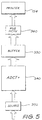
- the print pipeline shown in Fig. 5 expands the source ADCT+ image store into RGB pixel data in real time.
- the pixels are re-ordered from 8 x 8 blocks into 8 lines. They are then converted from RGB into C/M/Y/K, and printed.
- the expansion, conversion and printing process is performed four times for each copy to be printed: once for each of the Cyan, Magenta, Yellow and Black colour printing passes.
- data is supplied at 13.35 MBytes per second.
- the print pipeline consists of the following stages:
- the scan pipeline seen in Fig. 6, accepts the colour data from the scanner 152 and compresses this data to create the destination ADCT+ image 391.
- the scanner 152 of the colour laser copier 150 outputs synchronous 24 bit parallel RGB data which is fed to the composite line store 330 which acts as a buffer.
- the ADCT+ compressor 340 then uses direct memory access (DMA) to compress 8 lines of scanned data at a time. The compressed data is written into the destination ADCT+ image store 391.
- DMA direct memory access
- rendering The formation of pixel image data from object based data is known in the art as rendering.
- rendering opaque images involves writing pixel image data into memory.
- Compositing involves the combining of pixel images, generally by controlling the proportion of two or more source images in a destination or composited image.
- rendering transparent images involves compositing newly rendered objects with existing pixel image data.
- ADCT+ compressed image store 390 requires that the image must be calculated in essentially the same order as the printer 154 requires the output data for printing.
- Canon colour laser printing process printing occurs from the bottom left to the top right of an A3 page in landscape mode, as seen in Fig. 7.
- This method has the advantage of simplicity in that the image generation process need only consider each object in turn. This simplicity makes the method relatively easy to optimise for speed. Generally, a complete pixel mapped image store is required. For full colour A3 images at 400 dpi, this results in a memory requirement of approximately 96 MBytes per page.
- Band rendering has the disadvantage of complexity in that all of the objects must be stored, usually in a display list, and the appropriate section of each object must be created for each band.
- the painters algorithm can be used to overlay the visible objects in that band. This usually is substantially slower than when an entire page store is available, as each object must be created and clipped to each band.
- the ADCT+ image compression system used in the DTP system 100 works on blocks of 8 ⁇ 8 pixels.
- An A4 image with 6,480 lines ⁇ 4,632 pixels contains 810 ⁇ 579 pixel blocks.
- the rendering system in the DTP system 100 renders bands of 579 pixel blocks (8 vertical scan lines) in one pass. This rendering process must be repeated for 810 bands to render an entire A3 image.
- the combination of these techniques makes the DTP system 100 operate at very high speed.
- A3 size images can be created in as little as 6 seconds, and will typically take less than 20 seconds. This means that the DTP system 100 image generation speed is comparable to the Colour Copier print speed under most circumstances.
- image creation order must be from left to right of an A3 page in landscape format, or an A4 page in portrait format.
- Horizontal compositing runs to the 8 line buffer for the page image would be limited to eight pixels long, so only vertical runs are supported. There is no access to individual pixels of the page image without expanding and compressing the entire page.
- the screen image has no such limitations.
- the image can be built in any order, and runs can be either vertical or horizontal. Individual pixels can also be addressed in random order. This makes the generation of interactive user interfaces substantially easier.
Landscapes
- Engineering & Computer Science (AREA)
- Physics & Mathematics (AREA)
- General Physics & Mathematics (AREA)
- Theoretical Computer Science (AREA)
- Multimedia (AREA)
- General Engineering & Computer Science (AREA)
- Signal Processing (AREA)
- Discrete Mathematics (AREA)
- Image Processing (AREA)
- Compression Of Band Width Or Redundancy In Fax (AREA)
- Image Generation (AREA)
- Processing Or Creating Images (AREA)
- Controls And Circuits For Display Device (AREA)
- Document Processing Apparatus (AREA)
- Editing Of Facsimile Originals (AREA)
- Record Information Processing For Printing (AREA)
Claims (47)
- Agencement de traitement pipeline pour infographie afin de manipuler des données d'image comprimées, ledit agencement comprenant :une source (330, 392, 152, 385) de données ;une destination (305, 391, 370, 330, 360) de données ;un dispositif (340) de compression/décompression de données pour convertir des données de pixel d'image en données d'image comprimées, et vice versa ; etun manipulateur de données de pixel (320, 330) pour manipuler lesdites données de pixel d'image sous forme de pixel ;ledit dispositif de compression/décompression de données étant situé entre ladite source de données et ladite destination de données pour modifier la forme des données qui sont passées entre ladite source et ladite destination ; etledit manipulateur étant connecté audit dispositif de compression/décompression pour recevoir, en provenance de celui-ci et/ou envoyer à celui-ci, lesdites données de pixel d'image.
- Agencement selon la revendication 1, caractérisé en ce que lesdites données d'image sont relatives à une image affichable, et ledit manipulateur (330) est dimensionné pour contenir une partie limitée de la totalité des données de pixel d'image à partir desquelles une image affichable est formée, et pour permettre une manipulation de données individuelles parmi lesdites données de pixel d'image qui y sont contenues.
- Agencement selon la revendication 2, caractérisé en ce que lesdites données de pixel d'image comprennent un nombre prédéterminé de bandes, chacune d'elles comprenant un nombre prédéterminé de lignes adjacentes de l'image, un nombre sélectionné desdites bandes de données comprenant ladite partie limitée et étant traitées par ledit agencement pipeline.
- Agencement selon la revendication 3, caractérisé en ce que ledit nombre sélectionné de bandes sont traitées en série entre ladite source et ladite destination dans une seule opération pipeline par ledit agencement.
- Agencement selon l'une quelconque des revendications 1 à 4, caractérisé en ce que ledit manipulateur (330) est connecté entre ladite destination (360, 370) et ledit dispositif de compression/décompression pour recevoir des données de pixel d'image en provenance dudit dispositif de compression/décompression et pour envoyer les données de pixel d'image manipulées à ladite destination, la sortie du dispositif de compression/décompression étant des données d'image étendues reçues sous la forme de données d'image comprimées en provenance de ladite source (385, 390).
- Agencement selon la revendication 5, caractérisé en ce que ladite destination comprend un bus (305) de données et ledit manipulateur comprend un tampon (330) de synchronisation pour permettre audit bus de données et audit dispositif de compression/décompression de fonctionner à différentes cadences de données.
- Agencement selon la revendication 6, caractérisé en ce qu'un convertisseur (360) qui convertit des données d'image RGB en données d'image MCYK est connecté audit bus de données et ledit convertisseur effectue une sortie vers une imprimante (154).
- Agencement selon l'une quelconque des revendications 1 à 4, caractérisé en ce que ledit manipulateur (330) est connecté pour recevoir des données de pixel d'image en provenance dudit dispositif de compression/décompression, traiter celles-ci, et envoyer lesdites données de pixel d'image traitées audit dispositif de compression/décompression.
- Agencement selon la revendication 8, caractérisé en ce que ladite source et ladite destination envoient et reçoivent respectivement des données d'image comprimées.
- Agencement selon la revendication 9, caractérisé en ce que ladite source (392) et ladite destination (391) comprennent différents emplacements d'adresse du même moyen formant mémoire (390).
- Agencement selon la revendication 9, caractérisé en ce que ledit dispositif de compression/décompression étend des données d'image comprimées en provenance de ladite source pour une transmission audit dispositif de traitement, et comprime des données de pixel d'image en provenance dudit dispositif de traitement pour une transmission à ladite destination.
- Agencement selon la revendication 11, caractérisé en ce qu'une mémoire (395) apte à stocker au moins une bande de lignes d'image est interposée entre ledit manipulateur (330, 320) et ledit dispositif de compression/décompression.
- Agencement selon la revendication 11, caractérisé en ce que ledit manipulateur comprend un mécanisme d'infographie (320).
- Agencement selon l'une quelconque des revendications 1 à 4, caractérisé en ce que ledit manipulateur est connecté entre ladite source et ledit dispositif de compression/décompression pour recevoir des données de pixel d'image en provenance de ladite source et pour envoyer des données de pixel d'image manipulées audit dispositif de compression/décompression, ladite destination recevant des données d'image comprimées en provenance dudit dispositif de compression/décompres-sion.
- Agencement selon la revendication 14, caractérisé en ce que ladite source est un bus (305) de données et ledit manipulateur comprend un tampon (330) de synchronisation pour permettre audit bus de données et audit dispositif de compression/décompression de fonctionner à différentes cadences de données.
- Agencement selon la revendication 15, caractérisé en ce que ledit bus de données est connecté à un dispositif (152) de balayage d'image pour fournir lesdites données de pixel d'image.
- Agencement selon l'une quelconque des revendications précédentes, caractérisé en ce que ledit dispositif de compression/décompression de données utilise des procédés à transformation cosinusoïdale discrète adaptative pour comprimer et décompresser des données d'image.
- Agencement selon la revendication 17, caractérisé en ce que lesdits procédés à transformation cosinusoïdale discrète adaptative sont mis en oeuvre conformément aux spécifications techniques JPEG ISO/IEC JTC1/SC2/WG8.
- Système (100) de représentation pour créer des images de page en couleurs à partir d'un langage de description de page, ledit système comprenant :caractérisé en ce que ledit système comprend un agencement de traitement pipeline selon l'une quelconque des revendications 1 à 18 et connecté à au moins ledit moyen de restitution.un moyen de calcul (200) pour compiler, à partir dudit langage de description de page, une liste d'affichage (220) d'objets d'une image à créer ;un moyen de restitution (310) pour restituer des bandes de données d'image de pixel de ladite image à partir de ladite liste d'affichage ;
- Système selon la revendication 19, caractérisé en ce que ledit moyen de restitution comprend un processeur (310) de restitution ayant une entrée (391, 398) connectée audit moyen de calcul, pour convertir lesdits objets de la liste d'affichage en données d'image de pixel ;et ledit dispositif de traitement de données de pixel comprend un mécanisme (320) d'infographie et une mémoire (330) de composition, ledit mécanisme d'infographie ayant une première entrée (314) de données de pixel connectée audit processeur de restitution, une deuxième entrée (306) de données de pixel et une sortie de données de pixel étant connectées, par l'intermédiaire d'un bus (305) de composition, à ladite mémoire de composition ; dans lequelledit dispositif (340) de compression/décompression se présente sous la forme d'un compresseur-décompresseur, ledit compresseur-décompresseur (415) ayant un premier accès (452) de données comprimées connecté à un moyen (420) de stockage pouvant fonctionner comme ladite source de données et/ou ladite destination de données et un deuxième accès (410) de données de pixel connecté audit bus de composition, ledit bus de composition étant aussi connecté à ladite deuxième entrée (306) de données de pixel dudit processeur de restitution.
- Système selon la revendication 20, caractérisé en ce que ledit bus de composition est apte à acheminer des données d'image de pixel de couleurs rouge (R), verte (G), bleue (B) et mélangée (M).
- Système selon la revendication 21, caractérisé en ce que ledit système conserve une densité d'image équivalente à 400 points par pouce à tous les étages de traitement et de stockage d'image.
- Système selon l'une quelconque des revendications 20 à 22, caractérisé en ce que ledit système comprend en outre au moins un moyen (140, 154) d'affichage connecté audit bus de composition et apte à afficher ensemble des bandes de données d'image de pixel.
- Système selon la revendication 23, caractérisé en ce que ledit moyen d'affichage comprend une imprimante (154) configurée pour afficher lesdites bandes sous la forme d'une image de page.
- Système selon la revendication 24, caractérisé en ce que ladite imprimante est capable de produire une image de page dont le format est au moins le format standard A3 international.
- Système selon la revendication 24 ou 25, caractérisé en ce qu'entre ladite imprimante et ledit bus de composition est interposé un convertisseur (360) pour convertir des données d'image de pixel de couleurs rouge, verte et bleue en données d'image de pixel de couleurs magenta, cyan, jaune et noire pour une impression par ladite imprimante.
- Système selon la revendication 23, caractérisé en ce que ledit moyen d'affichage comprend un visuel électronique (140) comportant une mémoire d'affichage associée (370) connectée audit bus de composition, pour afficher ladite image de page.
- Système selon la revendication 27, caractérisé en ce que ledit visuel électronique est sélectionné parmi le groupe consistant en un visuel vidéo et un visuel à cristal liquide.
- Système selon la revendication 27 ou 28, caractérisé en ce que ledit système comprend en outre un dispositif (350) de panoramique/changement de focale ayant une entrée connectée audit bus de composition et une sortie connectée à ladite mémoire d'affichage, ledit dispositif de panoramique/changement de focale permettant à une partie sélectionnable de ladite image de page d'être affichée sur ledit visuel électronique.
- Système selon la revendication 27, 28 ou 29, caractérisé en ce que ledit moyen de calcul a un accès direct audit visuel pour écrire directement des données de pixel dans celui-ci, ces données ayant été générées par ledit moyen de calcul.
- Système selon l'une quelconque des revendications 21 à 30, caractérisé en ce que ledit système comprend en outre un dispositif (152) de balayage d'image connecté audit bus de composition et apte à lire des données d'image de pixel de couleurs rouge, verte et bleue correspondant à une image de page balayée par celui-ci.
- Système selon la revendication 31, caractérisé en ce que ledit système comprend en outre une imprimante (154) configurée pour afficher lesdites bandes sous la forme d'une image de page.
- Système selon la revendication 32, caractérisé en ce que ledit dispositif de balayage et ladite imprimante forment chacun une partie d'un copieur (150) à laser en couleurs.
- Système selon l'une quelconque des revendications 20 à 33, caractérisé en ce que des tables de Huffman (380) nécessaires à la fois pour une compression et une décompression, sont stockées dans ledit moyen de stockage (420) et sont transférées vers ledit dispositif de compression/décompression lorsque des opérations de compression et de décompression ont lieu, respectivement.
- Système selon l'une quelconque des revendications 20 à 34, caractérisé en ce que ledit moyen de calcul crée, à partir de ladite liste d'affichage, au moins une liste de restitution (397) comportant des objets à restituer par ledit processeur de restitution, ladite liste de restitution étant transférée (451) à partir dudit moyen de calcul par l'intermédiaire d'un bus de système vers ledit moyen de stockage, à partir duquel ledit processeur de restitution peut accéder à ladite liste de restitution.
- Système selon la revendication 35, caractérisé en ce que ledit moyen de calcul fournit en outre des données de police (399) qui sont stockées dans ledit moyen de stockage et qui sont accessibles par ledit processeur de restitution pour la génération d'images de texte et graphiques.
- Système selon l'une quelconque des revendications 19 à 36, caractérisé en ce que sont connectés audit moyen de calcul, des dispositifs (110) d'introduction par l'utilisateur sélectionnés dans le groupe consistant en un clavier (112), un bloc de numérisation (114), et une souris.
- Système selon l'une quelconque des revendications 20 à 37, caractérisé en ce que ledit système comprend en outre un moyen de stockage non volatil (120) connecté audit moyen de calcul, des données d'image pouvant être transférées à partir dudit moyen de stockage et vers celui-ci.
- Système selon l'une quelconque des revendications 19 à 38, caractérisé en ce que ledit moyen de calcul comprend en outre un moyen (215) pour une connexion à un réseau de communication (105) vers lequel peuvent être transférées des données, et vice versa.
- Système selon l'une quelconque des revendications 20 à 39, caractérisé en ce que lorsque lesdites bandes de données d'image de pixel sont comprimées, des codes de marqueur sont insérés pour identifier des bandes individuelles, lesdits codes de marqueur permettant à une bande quelconque d'une image de page comprimée d'être étendue par ledit compresseur-décompresseur et stockées dans ladite mémoire de composition, ladite bande étant introduite dans ladite deuxième entrée de pixel dudit mécanisme d'infographie qui compose ladite bande avec une sortie de données dudit processeur de restitution pour créer une bande éditée qui est transférée par l'intermédiaire de ladite sortie de données de pixel dudit mécanisme d'infographie, vers ladite mémoire de composition, ladite bande éditée à la suite de cela étant compressible par ledit compresseur-décompresseur, et stockable dans ledit moyen de stockage avec d'autres bandes de ladite image de page comprimée.
- Système selon l'une quelconque des revendications 20 à 40, caractérisé en ce que ladite mémoire de composition peut stocker un nombre entier de bandes de ladite image.
- Système selon la revendication 41, caractérisé en ce que ladite mémoire de composition peut stocker au moins 3 bandes de ladite image.
- Système selon l'une quelconque des revendications 19 à 42, caractérisé en ce que lesdites bandes comprennent chacune 8 lignes de ladite image de page.
- Système selon l'une quelconque des revendications 20 à 43, caractérisé en ce que ledit moyen de stockage est capable de stocker de multiples images de pages comprimées.
- Système selon la revendication 44, caractérisé en ce que chacune desdites images de pages comprimées occupe environ 4 Moctets.
- Système selon la revendication 45, caractérisé en ce que ledit moyen de stockage est composé de 32 Moctets de DRAM.
- Système selon l'une quelconque des revendications 20 à 46, caractérisé en ce que lesdites données d'image de pixel pour une image de page complète occupent un espace d'environ 96 Moctets qui est compressible à environ 4 Moctets pour rétention dans ledit moyen de stockage.
Applications Claiming Priority (9)
| Application Number | Priority Date | Filing Date | Title |
|---|---|---|---|
| AU1784/90 | 1990-08-16 | ||
| AU1785/90 | 1990-08-16 | ||
| AUPK178490 | 1990-08-16 | ||
| AUPK178590 | 1990-08-16 | ||
| AU178590 | 1990-08-16 | ||
| AU178490 | 1990-08-16 | ||
| AU3418/90 | 1990-11-19 | ||
| AU341890 | 1990-11-19 | ||
| AUPK341890 | 1990-11-19 |
Publications (3)
| Publication Number | Publication Date |
|---|---|
| EP0473340A2 EP0473340A2 (fr) | 1992-03-04 |
| EP0473340A3 EP0473340A3 (en) | 1993-02-24 |
| EP0473340B1 true EP0473340B1 (fr) | 1999-06-23 |
Family
ID=27157576
Family Applications (3)
| Application Number | Title | Priority Date | Filing Date |
|---|---|---|---|
| EP91307564A Expired - Lifetime EP0473341B1 (fr) | 1990-08-16 | 1991-08-15 | Mémoires d'image compressées pour graphiques haute-résolution par calculateur |
| EP91307565A Expired - Lifetime EP0475601B1 (fr) | 1990-08-16 | 1991-08-15 | Système en couleur de publication assisté par ordinateur |
| EP91307563A Expired - Lifetime EP0473340B1 (fr) | 1990-08-16 | 1991-08-15 | Structures pipeline pour traitement graphique par ordinateur en couleur |
Family Applications Before (2)
| Application Number | Title | Priority Date | Filing Date |
|---|---|---|---|
| EP91307564A Expired - Lifetime EP0473341B1 (fr) | 1990-08-16 | 1991-08-15 | Mémoires d'image compressées pour graphiques haute-résolution par calculateur |
| EP91307565A Expired - Lifetime EP0475601B1 (fr) | 1990-08-16 | 1991-08-15 | Système en couleur de publication assisté par ordinateur |
Country Status (4)
| Country | Link |
|---|---|
| US (4) | US5329616A (fr) |
| EP (3) | EP0473341B1 (fr) |
| JP (3) | JP2922680B2 (fr) |
| DE (3) | DE69131370T2 (fr) |
Families Citing this family (111)
| Publication number | Priority date | Publication date | Assignee | Title |
|---|---|---|---|---|
| US5329616A (en) | 1990-08-16 | 1994-07-12 | Canon Kabushiki Kaisha | Compressed image stores for high resolution computer graphics |
| EP0506482B1 (fr) * | 1991-03-29 | 1998-11-25 | Canon Kabushiki Kaisha | Traitement d'images |
| US5225911A (en) * | 1991-05-07 | 1993-07-06 | Xerox Corporation | Means for combining data of different frequencies for a raster output device |
| AU3274593A (en) * | 1991-12-13 | 1993-07-19 | Avid Technology, Inc. | Quantization table adjustment |
| US5355450A (en) * | 1992-04-10 | 1994-10-11 | Avid Technology, Inc. | Media composer with adjustable source material compression |
| WO1994001971A2 (fr) * | 1992-07-01 | 1994-01-20 | Avid Technology, Inc. | Systeme de montage electronique de film utilisant a la fois des formats de film et de bande magnetoscopique |
| US5638498A (en) * | 1992-11-10 | 1997-06-10 | Adobe Systems Incorporated | Method and apparatus for reducing storage requirements for display data |
| US5991515A (en) * | 1992-11-10 | 1999-11-23 | Adobe Systems Incorporated | Method and apparatus for compressing and decompressing data prior to display |
| US5539865A (en) * | 1992-11-10 | 1996-07-23 | Adobe Systems, Inc. | Method and apparatus for processing data for a visual-output device with reduced buffer memory requirements |
| JPH06274612A (ja) * | 1993-03-17 | 1994-09-30 | Matsushita Electric Ind Co Ltd | 画像処理装置 |
| US5850540A (en) * | 1993-07-02 | 1998-12-15 | Sony Corporation | Method and apparatus for time-sharing CPU system bus in image generation system |
| EP0650140B1 (fr) * | 1993-10-18 | 1999-08-25 | Hewlett-Packard Company | Auvrissement de la densité de points imprimés dans une matrice de points |
| US6323958B1 (en) * | 1993-11-19 | 2001-11-27 | Canon Kabushiki Kaisha | Printing apparatus |
| JP2611637B2 (ja) * | 1993-11-22 | 1997-05-21 | 日本電気株式会社 | 画像圧縮伸長装置 |
| US6006013A (en) * | 1994-05-18 | 1999-12-21 | Xerox Corporation | Object optimized printing system and method |
| US6327043B1 (en) | 1994-05-18 | 2001-12-04 | Xerox Corporation | Object optimized printing system and method |
| US5672357A (en) * | 1994-07-01 | 1997-09-30 | Monsanto Company | Method and device for implantation of large diameter objects in bovines |
| US5595752A (en) * | 1994-07-01 | 1997-01-21 | Monsanto Company | Increasing dressing percentage and carcass weight in finishing beef cattle |
| TW304254B (fr) * | 1994-07-08 | 1997-05-01 | Hitachi Ltd | |
| US5784503A (en) * | 1994-08-26 | 1998-07-21 | Unisys Corp | Check reader utilizing sync-tags to match the images at the front and rear faces of a check |
| JP3554034B2 (ja) * | 1994-09-02 | 2004-08-11 | キヤノン株式会社 | カラー印刷装置及びその方法 |
| AUPM822394A0 (en) * | 1994-09-16 | 1994-10-13 | Canon Inc. | Object based rendering system |
| US5805781A (en) * | 1994-12-07 | 1998-09-08 | Hewlett-Packard Company | Printer method and apparatus for combining sub-images to eliminate image artifacts |
| US6243172B1 (en) * | 1995-01-18 | 2001-06-05 | Varis Corporation | Method and system for merging variable text and images into bitmaps defined by a page description language |
| US5729665A (en) | 1995-01-18 | 1998-03-17 | Varis Corporation | Method of utilizing variable data fields with a page description language |
| EP0770300A2 (fr) * | 1995-04-12 | 1997-05-02 | Eastman Kodak Company | Stockage a grande capacite d'images de documents comprimees pour imprimantes couleurs numeriques |
| AUPN229195A0 (en) * | 1995-04-12 | 1995-05-04 | Eastman Kodak Company | A color plotter using lift printing technology |
| AU5867696A (en) * | 1995-06-06 | 1996-12-24 | Apple Computer, Inc. | System and method for image generation using compression |
| US7715642B1 (en) * | 1995-06-06 | 2010-05-11 | Hewlett-Packard Development Company, L.P. | Bitmap image compressing |
| DE69632644T2 (de) * | 1995-07-03 | 2005-05-25 | Electronics for Imaging, Inc., Foster City | Bilderzeugung für seitendrucker |
| JPH0944130A (ja) * | 1995-07-28 | 1997-02-14 | Sony Corp | 映像装置 |
| US5708717A (en) * | 1995-11-29 | 1998-01-13 | Alasia; Alfred | Digital anti-counterfeiting software method and apparatus |
| TW348239B (en) * | 1996-06-28 | 1998-12-21 | Cirrus Logic Inc | Embedding a transparency enable bit as part of a resizing bit block transfer operation |
| US6269190B1 (en) | 1996-09-24 | 2001-07-31 | Electronics For Imaging, Inc. | Computer system for processing images using a virtual frame buffer |
| US6094453A (en) * | 1996-10-11 | 2000-07-25 | Digital Accelerator Corporation | Digital data compression with quad-tree coding of header file |
| US6023556A (en) * | 1997-01-29 | 2000-02-08 | Gammagrapnx, Inc. | Processing print job image data |
| US5835104A (en) * | 1997-04-23 | 1998-11-10 | S3 Incorporated | Variable band size compositing buffer method and apparatus |
| US6487568B1 (en) * | 1997-07-18 | 2002-11-26 | Tesseron, Ltd. | Method and system for flowing data to an arbitrary path defined by a page description language |
| US7302438B1 (en) | 1997-07-18 | 2007-11-27 | Tesseron Ltd. | Method and system for flowing data to an arbitrary path defined by a page description language |
| US6049390A (en) * | 1997-11-05 | 2000-04-11 | Barco Graphics Nv | Compressed merging of raster images for high speed digital printing |
| US6247011B1 (en) * | 1997-12-02 | 2001-06-12 | Digital-Net, Inc. | Computerized prepress authoring for document creation |
| US6115134A (en) * | 1997-12-05 | 2000-09-05 | Hewlett-Packard Company | Scan line splitting in a multi-staged image processing pipeline |
| US6289364B1 (en) * | 1997-12-22 | 2001-09-11 | Adobe Systems, Inc. | Transparency processing in a page description language |
| US6466210B1 (en) * | 1997-12-22 | 2002-10-15 | Adobe Systems Incorporated | Blending image data using layers |
| US6323858B1 (en) * | 1998-05-13 | 2001-11-27 | Imove Inc. | System for digitally capturing and recording panoramic movies |
| AU4184399A (en) | 1998-05-13 | 1999-11-29 | Infinite Pictures Inc. | Panoramic movies which simulate movement through multidimensional space |
| US6606413B1 (en) * | 1998-06-01 | 2003-08-12 | Trestle Acquisition Corp. | Compression packaged image transmission for telemicroscopy |
| US20040083085A1 (en) * | 1998-06-01 | 2004-04-29 | Zeineh Jack A. | Integrated virtual slide and live microscope system |
| US7315979B1 (en) | 1998-11-09 | 2008-01-01 | Tesseron Ltd. | Method and system for dynamic flowing data to an arbitrary path defined by a page description language |
| US6249290B1 (en) * | 1998-12-14 | 2001-06-19 | Sony Corporation | Object oriented zooming graphical user interface |
| US7050085B1 (en) | 2000-10-26 | 2006-05-23 | Imove, Inc. | System and method for camera calibration |
| US6690374B2 (en) | 1999-05-12 | 2004-02-10 | Imove, Inc. | Security camera system for tracking moving objects in both forward and reverse directions |
| US6738073B2 (en) * | 1999-05-12 | 2004-05-18 | Imove, Inc. | Camera system with both a wide angle view and a high resolution view |
| US6411301B1 (en) | 1999-10-28 | 2002-06-25 | Nintendo Co., Ltd. | Graphics system interface |
| US6452600B1 (en) | 1999-10-28 | 2002-09-17 | Nintendo Co., Ltd. | Graphics system interface |
| US6618048B1 (en) | 1999-10-28 | 2003-09-09 | Nintendo Co., Ltd. | 3D graphics rendering system for performing Z value clamping in near-Z range to maximize scene resolution of visually important Z components |
| US7050639B1 (en) * | 1999-11-24 | 2006-05-23 | General Electric Company | Image data compression employing multiple compression code tables |
| EP1109093A1 (fr) * | 1999-12-14 | 2001-06-20 | Sun Microsystems, Inc. | Méthode et dispositif d'impression de graphique transparent |
| US6490696B1 (en) | 1999-12-15 | 2002-12-03 | Electronics For Imaging, Inc. | System and method for printer output regression testing using display lists |
| US7505046B1 (en) | 2000-05-02 | 2009-03-17 | Adobe Systems Incorporated | Preserving opaque-like rendering in transparent 2D graphics using knockout groups |
| US7483042B1 (en) * | 2000-01-13 | 2009-01-27 | Ati International, Srl | Video graphics module capable of blending multiple image layers |
| CA2398171C (fr) * | 2000-01-25 | 2016-04-05 | Vistaprint Usa, Inc. | Gestion d'impressions |
| FR2804231B1 (fr) | 2000-01-25 | 2002-11-08 | Vistaprint Usa Inc | Impression centralisee de documents commerciaux en faibles volumes sur des machines auparavant limitees a des tres gros tirages |
| US6859862B1 (en) | 2000-04-07 | 2005-02-22 | Nintendo Co., Ltd. | Method and apparatus for software management of on-chip cache |
| US6857061B1 (en) | 2000-04-07 | 2005-02-15 | Nintendo Co., Ltd. | Method and apparatus for obtaining a scalar value directly from a vector register |
| US7062087B1 (en) | 2000-05-16 | 2006-06-13 | International Busniness Machines Corporation | System and method for optimizing color compression using transparency control bits |
| US7167259B2 (en) | 2000-05-16 | 2007-01-23 | International Business Machines Corporation | System and method for merging line work objects using tokenization and selective compression |
| US7119813B1 (en) | 2000-06-02 | 2006-10-10 | Nintendo Co., Ltd. | Variable bit field encoding |
| US7032180B2 (en) * | 2000-08-14 | 2006-04-18 | Twin Communications Of America, Inc. | User interface rendering component environment |
| US6609977B1 (en) | 2000-08-23 | 2003-08-26 | Nintendo Co., Ltd. | External interfaces for a 3D graphics system |
| US6867781B1 (en) | 2000-08-23 | 2005-03-15 | Nintendo Co., Ltd. | Graphics pipeline token synchronization |
| US7196710B1 (en) | 2000-08-23 | 2007-03-27 | Nintendo Co., Ltd. | Method and apparatus for buffering graphics data in a graphics system |
| US6999100B1 (en) | 2000-08-23 | 2006-02-14 | Nintendo Co., Ltd. | Method and apparatus for anti-aliasing in a graphics system |
| US6707458B1 (en) | 2000-08-23 | 2004-03-16 | Nintendo Co., Ltd. | Method and apparatus for texture tiling in a graphics system |
| US6664962B1 (en) | 2000-08-23 | 2003-12-16 | Nintendo Co., Ltd. | Shadow mapping in a low cost graphics system |
| US6580430B1 (en) | 2000-08-23 | 2003-06-17 | Nintendo Co., Ltd. | Method and apparatus for providing improved fog effects in a graphics system |
| US7002591B1 (en) | 2000-08-23 | 2006-02-21 | Nintendo Co., Ltd. | Method and apparatus for interleaved processing of direct and indirect texture coordinates in a graphics system |
| US6937245B1 (en) | 2000-08-23 | 2005-08-30 | Nintendo Co., Ltd. | Graphics system with embedded frame buffer having reconfigurable pixel formats |
| US6980218B1 (en) | 2000-08-23 | 2005-12-27 | Nintendo Co., Ltd. | Method and apparatus for efficient generation of texture coordinate displacements for implementing emboss-style bump mapping in a graphics rendering system |
| US6825851B1 (en) | 2000-08-23 | 2004-11-30 | Nintendo Co., Ltd. | Method and apparatus for environment-mapped bump-mapping in a graphics system |
| US7184059B1 (en) | 2000-08-23 | 2007-02-27 | Nintendo Co., Ltd. | Graphics system with copy out conversions between embedded frame buffer and main memory |
| US6606689B1 (en) | 2000-08-23 | 2003-08-12 | Nintendo Co., Ltd. | Method and apparatus for pre-caching data in audio memory |
| US6636214B1 (en) | 2000-08-23 | 2003-10-21 | Nintendo Co., Ltd. | Method and apparatus for dynamically reconfiguring the order of hidden surface processing based on rendering mode |
| US6700586B1 (en) | 2000-08-23 | 2004-03-02 | Nintendo Co., Ltd. | Low cost graphics with stitching processing hardware support for skeletal animation |
| US7134960B1 (en) | 2000-08-23 | 2006-11-14 | Nintendo Co., Ltd. | External interfaces for a 3D graphics system |
| US6811489B1 (en) | 2000-08-23 | 2004-11-02 | Nintendo Co., Ltd. | Controller interface for a graphics system |
| US6639595B1 (en) | 2000-08-23 | 2003-10-28 | Nintendo Co., Ltd. | Achromatic lighting in a graphics system and method |
| US6664958B1 (en) | 2000-08-23 | 2003-12-16 | Nintendo Co., Ltd. | Z-texturing |
| US7538772B1 (en) | 2000-08-23 | 2009-05-26 | Nintendo Co., Ltd. | Graphics processing system with enhanced memory controller |
| US7034828B1 (en) | 2000-08-23 | 2006-04-25 | Nintendo Co., Ltd. | Recirculating shade tree blender for a graphics system |
| US6697074B2 (en) | 2000-11-28 | 2004-02-24 | Nintendo Co., Ltd. | Graphics system interface |
| US7003588B1 (en) | 2001-08-22 | 2006-02-21 | Nintendo Co., Ltd. | Peripheral devices for a video game system |
| US6920618B2 (en) * | 2001-12-21 | 2005-07-19 | Hewlett-Packard Development Company, L.P. | System and method for configuring graphics pipelines in a computer graphical display system |
| US6621586B1 (en) * | 2002-04-10 | 2003-09-16 | Texas Instruments Incorporated | Accurately scheduling rendering of bands in a printer |
| US7317547B2 (en) * | 2002-05-07 | 2008-01-08 | Hewlett-Packard Development Company, L.P. | Single compressor with plural decompressors for multi-laser printing |
| US6982727B2 (en) * | 2002-07-23 | 2006-01-03 | Broadcom Corporation | System and method for providing graphics using graphical engine |
| US8045215B2 (en) * | 2002-10-18 | 2011-10-25 | Hewlett-Packard Development Company, L.P. | Printer object list resolutions |
| DE10329372A1 (de) * | 2003-06-30 | 2005-02-10 | Siemens Ag | Rechnergestütztes Bearbeitungsverfahren für ein über eine Anzeigeeinrichtung an einen Betrachter ausgebbares Bild |
| EP1524865A1 (fr) * | 2003-10-17 | 2005-04-20 | Nederlandse Organisatie Voor Toegepast-Natuurwetenschappelijk Onderzoek Tno | Dispositif d'affichage multi-plans pour l'affichage d'images se chevauchant |
| US7450775B2 (en) * | 2004-03-12 | 2008-11-11 | Kabushiki Kaisha Toshiba | Image processing apparatus for efficient storage of variable block length data |
| CN1728761A (zh) | 2004-06-16 | 2006-02-01 | 株式会社理光 | 图像处理装置,图像处理方法及图像处理用程序 |
| WO2007115321A2 (fr) | 2006-04-04 | 2007-10-11 | Photonic Biosystems, Inc. | Mesure visuelle, continue et simultanée de la concentration d'ammoniac en solution et des ions hydrogène |
| JP5331175B2 (ja) | 2011-08-24 | 2013-10-30 | 出光工業株式会社 | 絶縁スペーサの溝加工装置及びその溝加工方法 |
| JP5436526B2 (ja) | 2011-12-06 | 2014-03-05 | 株式会社ソニー・コンピュータエンタテインメント | グラフィックスコマンド生成装置、グラフィックスコマンド生成方法、サーバ装置、およびクライアント装置 |
| KR20130094447A (ko) * | 2012-02-16 | 2013-08-26 | 한국전자통신연구원 | 컷스루 메모리를 이용한 이미지 데이터 처리 장치 및 그 방법 |
| US8994750B2 (en) | 2012-06-11 | 2015-03-31 | 2236008 Ontario Inc. | Cell-based composited windowing system |
| JP2015084172A (ja) * | 2013-10-25 | 2015-04-30 | キヤノン株式会社 | 情報処理装置及びプログラム、制御方法 |
| CN104361556B (zh) * | 2014-10-22 | 2017-11-28 | 华为技术有限公司 | 一种图像合成方法和图像芯片以及图像设备 |
| US20180181269A1 (en) * | 2016-12-23 | 2018-06-28 | tronc, Inc. | Systems and methods for online-content and print-content assembly |
| US11488349B2 (en) | 2019-06-28 | 2022-11-01 | Ati Technologies Ulc | Method and apparatus for alpha blending images from different color formats |
| JP7531281B2 (ja) | 2020-01-24 | 2024-08-09 | キヤノン株式会社 | 画像処理装置、画像処理方法 |
Family Cites Families (29)
| Publication number | Priority date | Publication date | Assignee | Title |
|---|---|---|---|---|
| US3916095A (en) * | 1972-02-17 | 1975-10-28 | Dacom Inc | Dual-line data compression method and system for compressing, transmitting and reproducing facsimile data |
| US4271476A (en) * | 1979-07-17 | 1981-06-02 | International Business Machines Corporation | Method and apparatus for rotating the scan format of digital images |
| US4679038A (en) * | 1983-07-18 | 1987-07-07 | International Business Machines Corporation | Band buffer display system |
| US4568983A (en) * | 1983-12-07 | 1986-02-04 | The Mead Corporation | Image data compression/decompression |
| US4791680A (en) * | 1986-03-25 | 1988-12-13 | Matsushita Electric Industrial Co. | Image data converter |
| US4843632A (en) * | 1986-05-09 | 1989-06-27 | Prodigy Systems Corporation | Compressed image expansion system |
| JPS62272366A (ja) * | 1986-05-21 | 1987-11-26 | Hitachi Ltd | 図形情報処理装置 |
| US4868557A (en) * | 1986-06-04 | 1989-09-19 | Apple Computer, Inc. | Video display apparatus |
| JPS63106080A (ja) * | 1986-06-27 | 1988-05-11 | Hitachi Ltd | 画像表示方式 |
| DE3735349A1 (de) * | 1986-10-18 | 1988-04-28 | Toshiba Kawasaki Kk | Bildpresservorrichtung |
| US4862154A (en) * | 1986-10-31 | 1989-08-29 | International Business Machines Corporation | Image display processor for graphics workstation |
| US4896275A (en) * | 1987-07-10 | 1990-01-23 | Bull Hn Information Systems Inc. | Full page graphics image display data reduction |
| ATE115749T1 (de) * | 1987-07-31 | 1994-12-15 | Qms Inc | Seitendrucksystem mit virtuellem speicher. |
| US4823201A (en) * | 1987-11-16 | 1989-04-18 | Technology, Inc. 64 | Processor for expanding a compressed video signal |
| EP0326137A3 (fr) * | 1988-01-27 | 1991-10-02 | Fuji Photo Film Co., Ltd. | Système de traitement d'image |
| US4897717A (en) * | 1988-03-30 | 1990-01-30 | Starsignal, Inc. | Computer-based video compression system |
| JP2787830B2 (ja) | 1988-06-10 | 1998-08-20 | キヤノン株式会社 | 画像処理装置及び方法 |
| JPH02195480A (ja) * | 1989-01-25 | 1990-08-02 | Hitachi Ltd | 画像データの検索方式 |
| US5526128A (en) * | 1989-06-19 | 1996-06-11 | Matsushita Electric Industrial Co., Ltd. | Image producing apparatus with memory unit having an image memory area of changeable storage capacity |
| US5241653A (en) * | 1990-04-12 | 1993-08-31 | Adobe Systems Incorporated | Apparatus and method for adjusting and displaying scaled, rasterized characters |
| US5191406A (en) * | 1990-04-20 | 1993-03-02 | Nikon Corporation | Method and apparatus for rapid scanning of color images |
| JPH0447376A (ja) * | 1990-06-12 | 1992-02-17 | Toshiba Corp | 情報処理装置および情報処理方法 |
| JP3043469B2 (ja) | 1990-07-05 | 2000-05-22 | キヤノン株式会社 | 大容量カラーレーザプリントシステム |
| US5459823A (en) | 1990-07-05 | 1995-10-17 | Canon Kabushiki Kaisha | Graphics engine for true colour 2D graphics |
| DE69132625T2 (de) | 1990-07-31 | 2001-10-31 | Canon K.K., Tokio/Tokyo | Gerät zur Bildverarbeitung |
| US5509115A (en) * | 1990-08-08 | 1996-04-16 | Peerless Systems Corporation | Method and apparatus for displaying a page with graphics information on a continuous synchronous raster output device |
| US5329616A (en) | 1990-08-16 | 1994-07-12 | Canon Kabushiki Kaisha | Compressed image stores for high resolution computer graphics |
| JP3256982B2 (ja) * | 1991-05-14 | 2002-02-18 | 富士ゼロックス株式会社 | 画像処理装置 |
| US5838334A (en) * | 1994-11-16 | 1998-11-17 | Dye; Thomas A. | Memory and graphics controller which performs pointer-based display list video refresh operations |
-
1991
- 1991-08-13 US US07/744,703 patent/US5329616A/en not_active Expired - Lifetime
- 1991-08-13 US US07/744,540 patent/US5801716A/en not_active Expired - Lifetime
- 1991-08-13 US US07/744,522 patent/US6020894A/en not_active Expired - Lifetime
- 1991-08-15 DE DE69131370T patent/DE69131370T2/de not_active Expired - Lifetime
- 1991-08-15 EP EP91307564A patent/EP0473341B1/fr not_active Expired - Lifetime
- 1991-08-15 EP EP91307565A patent/EP0475601B1/fr not_active Expired - Lifetime
- 1991-08-15 DE DE69128063T patent/DE69128063T2/de not_active Expired - Lifetime
- 1991-08-15 DE DE69125549T patent/DE69125549T2/de not_active Expired - Lifetime
- 1991-08-15 EP EP91307563A patent/EP0473340B1/fr not_active Expired - Lifetime
- 1991-08-16 JP JP3206049A patent/JP2922680B2/ja not_active Expired - Lifetime
- 1991-08-16 JP JP20605091A patent/JP3255943B2/ja not_active Expired - Lifetime
- 1991-08-16 JP JP20605491A patent/JP3166977B2/ja not_active Expired - Lifetime
-
1999
- 1999-08-06 US US09/369,281 patent/US7012620B1/en not_active Expired - Fee Related
Also Published As
| Publication number | Publication date |
|---|---|
| JP3166977B2 (ja) | 2001-05-14 |
| EP0475601A3 (en) | 1993-02-24 |
| EP0473341A2 (fr) | 1992-03-04 |
| US5801716A (en) | 1998-09-01 |
| JP3255943B2 (ja) | 2002-02-12 |
| US5329616A (en) | 1994-07-12 |
| EP0475601A2 (fr) | 1992-03-18 |
| US6020894A (en) | 2000-02-01 |
| US7012620B1 (en) | 2006-03-14 |
| DE69125549T2 (de) | 1997-09-04 |
| DE69125549D1 (de) | 1997-05-15 |
| EP0473341B1 (fr) | 1997-04-09 |
| JPH06261202A (ja) | 1994-09-16 |
| DE69128063D1 (de) | 1997-12-04 |
| EP0475601B1 (fr) | 1997-10-29 |
| JP2922680B2 (ja) | 1999-07-26 |
| JPH06243243A (ja) | 1994-09-02 |
| EP0473340A3 (en) | 1993-02-24 |
| DE69131370T2 (de) | 1999-11-18 |
| EP0473340A2 (fr) | 1992-03-04 |
| JPH0793559A (ja) | 1995-04-07 |
| EP0473341A3 (en) | 1993-02-24 |
| DE69131370D1 (de) | 1999-07-29 |
| DE69128063T2 (de) | 1998-03-19 |
Similar Documents
| Publication | Publication Date | Title |
|---|---|---|
| EP0473340B1 (fr) | Structures pipeline pour traitement graphique par ordinateur en couleur | |
| US6049390A (en) | Compressed merging of raster images for high speed digital printing | |
| RU2360288C2 (ru) | Файлы, содержащие смешанный растр | |
| CA2221752C (fr) | Procede et systeme pour reduire les besoins en memoire pour des donnees d'affichage | |
| KR100989010B1 (ko) | 그래픽 데이터 및 디지털 문서 프로세싱의 시각적표현들을 생성하는 시스템 및 방법 | |
| JPH08287238A (ja) | 画像の合成方法及び装置 | |
| JPH07501164A (ja) | ビデオ/グラフィックメモリシステム | |
| US5195174A (en) | Image data processing apparatus capable of composing one image from a plurality of images | |
| US6238105B1 (en) | Processor/memory non-intensive rendering for page printers | |
| JP3109817B2 (ja) | 画像処理装置 | |
| US6421059B1 (en) | Apparatus and method for rendering characters into a memory | |
| JP3082930B2 (ja) | 画像処理装置 | |
| JPH04215189A (ja) | 画像記録装置 | |
| JP3278149B2 (ja) | 画像処理装置 | |
| JPH0550666A (ja) | プリント装置 | |
| JPH0437795A (ja) | ハイビジョン用文字表示装置 | |
| Dixit | Hardware And Software Architectural Considerations In Image And Graphics Processing | |
| JP2003036445A (ja) | 画像処理装置 | |
| JPH0765177A (ja) | 画像処理システムおよび画像処理装置 | |
| JPH05244388A (ja) | 画像記録装置 | |
| JPH0437796A (ja) | テキスト画面表示装置 | |
| JPH02135867A (ja) | 文字図形出力装置 | |
| JPH0564002A (ja) | カラー画像処理装置 | |
| JPH04342363A (ja) | 画像情報処理装置 | |
| HK1015913B (en) | Image rendering for page printers |
Legal Events
| Date | Code | Title | Description |
|---|---|---|---|
| PUAI | Public reference made under article 153(3) epc to a published international application that has entered the european phase |
Free format text: ORIGINAL CODE: 0009012 |
|
| AK | Designated contracting states |
Kind code of ref document: A2 Designated state(s): DE FR GB IT |
|
| PUAL | Search report despatched |
Free format text: ORIGINAL CODE: 0009013 |
|
| AK | Designated contracting states |
Kind code of ref document: A3 Designated state(s): DE FR GB IT |
|
| 17P | Request for examination filed |
Effective date: 19930709 |
|
| 17Q | First examination report despatched |
Effective date: 19950718 |
|
| GRAG | Despatch of communication of intention to grant |
Free format text: ORIGINAL CODE: EPIDOS AGRA |
|
| GRAG | Despatch of communication of intention to grant |
Free format text: ORIGINAL CODE: EPIDOS AGRA |
|
| GRAH | Despatch of communication of intention to grant a patent |
Free format text: ORIGINAL CODE: EPIDOS IGRA |
|
| GRAH | Despatch of communication of intention to grant a patent |
Free format text: ORIGINAL CODE: EPIDOS IGRA |
|
| GRAA | (expected) grant |
Free format text: ORIGINAL CODE: 0009210 |
|
| AK | Designated contracting states |
Kind code of ref document: B1 Designated state(s): DE FR GB IT |
|
| REF | Corresponds to: |
Ref document number: 69131370 Country of ref document: DE Date of ref document: 19990729 |
|
| ET | Fr: translation filed | ||
| ITF | It: translation for a ep patent filed | ||
| PLBE | No opposition filed within time limit |
Free format text: ORIGINAL CODE: 0009261 |
|
| STAA | Information on the status of an ep patent application or granted ep patent |
Free format text: STATUS: NO OPPOSITION FILED WITHIN TIME LIMIT |
|
| 26N | No opposition filed | ||
| REG | Reference to a national code |
Ref country code: GB Ref legal event code: 732E |
|
| REG | Reference to a national code |
Ref country code: FR Ref legal event code: TP |
|
| REG | Reference to a national code |
Ref country code: GB Ref legal event code: IF02 |
|
| PGFP | Annual fee paid to national office [announced via postgrant information from national office to epo] |
Ref country code: FR Payment date: 20090821 Year of fee payment: 19 |
|
| PGFP | Annual fee paid to national office [announced via postgrant information from national office to epo] |
Ref country code: GB Payment date: 20090827 Year of fee payment: 19 Ref country code: DE Payment date: 20090831 Year of fee payment: 19 |
|
| PGFP | Annual fee paid to national office [announced via postgrant information from national office to epo] |
Ref country code: IT Payment date: 20090812 Year of fee payment: 19 |
|
| GBPC | Gb: european patent ceased through non-payment of renewal fee |
Effective date: 20100815 |
|
| REG | Reference to a national code |
Ref country code: FR Ref legal event code: ST Effective date: 20110502 |
|
| PG25 | Lapsed in a contracting state [announced via postgrant information from national office to epo] |
Ref country code: IT Free format text: LAPSE BECAUSE OF NON-PAYMENT OF DUE FEES Effective date: 20100815 |
|
| REG | Reference to a national code |
Ref country code: DE Ref legal event code: R119 Ref document number: 69131370 Country of ref document: DE Effective date: 20110301 |
|
| PG25 | Lapsed in a contracting state [announced via postgrant information from national office to epo] |
Ref country code: DE Free format text: LAPSE BECAUSE OF NON-PAYMENT OF DUE FEES Effective date: 20110301 Ref country code: FR Free format text: LAPSE BECAUSE OF NON-PAYMENT OF DUE FEES Effective date: 20100831 |
|
| PG25 | Lapsed in a contracting state [announced via postgrant information from national office to epo] |
Ref country code: GB Free format text: LAPSE BECAUSE OF NON-PAYMENT OF DUE FEES Effective date: 20100815 |