EP0472341B1 - Métier à tricoter rectiligne avec des platines oscillants et des barres de presse - Google Patents
Métier à tricoter rectiligne avec des platines oscillants et des barres de presse Download PDFInfo
- Publication number
- EP0472341B1 EP0472341B1 EP91307414A EP91307414A EP0472341B1 EP 0472341 B1 EP0472341 B1 EP 0472341B1 EP 91307414 A EP91307414 A EP 91307414A EP 91307414 A EP91307414 A EP 91307414A EP 0472341 B1 EP0472341 B1 EP 0472341B1
- Authority
- EP
- European Patent Office
- Prior art keywords
- swing
- controller
- sinkers
- sinker
- action
- Prior art date
- Legal status (The legal status is an assumption and is not a legal conclusion. Google has not performed a legal analysis and makes no representation as to the accuracy of the status listed.)
- Expired - Lifetime
Links
Images

Classifications
-
- D—TEXTILES; PAPER
- D04—BRAIDING; LACE-MAKING; KNITTING; TRIMMINGS; NON-WOVEN FABRICS
- D04B—KNITTING
- D04B15/00—Details of, or auxiliary devices incorporated in, weft knitting machines, restricted to machines of this kind
- D04B15/32—Cam systems or assemblies for operating knitting instruments
- D04B15/36—Cam systems or assemblies for operating knitting instruments for flat-bed knitting machines
- D04B15/362—Cam systems or assemblies for operating knitting instruments for flat-bed knitting machines with two needle beds in V-formation
-
- D—TEXTILES; PAPER
- D04—BRAIDING; LACE-MAKING; KNITTING; TRIMMINGS; NON-WOVEN FABRICS
- D04B—KNITTING
- D04B15/00—Details of, or auxiliary devices incorporated in, weft knitting machines, restricted to machines of this kind
- D04B15/30—Driving devices for thread-carrier rods
-
- D—TEXTILES; PAPER
- D04—BRAIDING; LACE-MAKING; KNITTING; TRIMMINGS; NON-WOVEN FABRICS
- D04B—KNITTING
- D04B15/00—Details of, or auxiliary devices incorporated in, weft knitting machines, restricted to machines of this kind
- D04B15/06—Sinkers
-
- D—TEXTILES; PAPER
- D04—BRAIDING; LACE-MAKING; KNITTING; TRIMMINGS; NON-WOVEN FABRICS
- D04B—KNITTING
- D04B15/00—Details of, or auxiliary devices incorporated in, weft knitting machines, restricted to machines of this kind
- D04B15/88—Take-up or draw-off devices for knitting products
- D04B15/90—Take-up or draw-off devices for knitting products for flat-bed knitting machines
-
- D—TEXTILES; PAPER
- D04—BRAIDING; LACE-MAKING; KNITTING; TRIMMINGS; NON-WOVEN FABRICS
- D04B—KNITTING
- D04B7/00—Flat-bed knitting machines with independently-movable needles
Definitions
- the present invention relates to a flat knitting machine provided with swing sinkers and presser bars.
- Such a flat knitting machine comprises a multiplicity of knitting needles arranged in parallel relationship on needle beds and swing sinkers interposed between the knitting needles.
- the swing sinkers are provided with knitting yarn holding portions so that a row of stitches hooked on the knitting needles can be prevented from being lifted up when the knitting needles move upward for producing another row of stitches during the knitting operation. More particularly, the thread of yarn for knitting is maintained by the action of the knitting yarn holding portions of the swing sinkers and the chain of stitches looped on the knitting needles will be cleared off by knock-over action for knitting a succeeding chain.
- a knitted fabric presser device is arranged on the carriage for moving a presser bar thereof into the above space for holding the chain of stitches.
- the space is occupied by the projecting sinkers thus leaving less room which is too small to accept the presser bars. Accordingly, it is hardly feasible for a flat knitting machine in which each carriage is intended to change its moving direction at two desired positions on the corresponding needle bed to have a presser bar arranged for movement into and out from the space.
- Flat knitting machines including a presser bar but no swing sinkers are known from GB-A-2 097 431 or US-A-3 685 317.
- the present invention has been invented in view of the foregoing points and its object is to provide a flat knitting machine in which the swing sinkers and the presser bar are arranged for movement into and out from the space between the two needle beds in relative relationship so that either of the swing sinkers or the presser bar can act on the loops or knitted stitches of yarn thus allowing both plain and rib knitting operations to be carried out equally with no troubles.
- a flat knitting machine comprises: a multiplicity of knitting needles arranged on needle beds; sinkers provided between the knitting needles for swing movement; and carriages arranged for leftward and rightward movement on the needle beds, which can change their moving direction at two given points.
- each of the carriage has a sinker swing action controller and a stitch presser controller both linked to each other for co-movement and activated by a driver device directly coupled to the stitch presser controller.
- the stitch presser controller is coupled to a driver device for supporting a presser bar provided on the close-to-upper-end of the carriage.
- the presser bar is arranged for being moved into and out from a toothed opening provided between the top ends of the two needle beds by the action of the stitch presser controller.
- the sinker swing action controller is arranged for actuating the sinkers in co-movement with the stitch presser controller. Accordingly, when the carriage changes its moving direction, both the presser bar and the sinkers are actuated to perform advancing and retracting actions relative to each other by the co-movement of the sinker swing action controller and the stitch presser controller.
- the driver device actuates the stitch presser controller and then, the sinker swing action controller linked to the stitch presser controller. Then, the presser bar of the stitch presser controller advances into the space provided between the uppermost ends of the two needle beds and presses down a knitted portion of fabric during e.g. rib knitting.
- the sinkers are actuated to perform a swing action for opening the space which remains closed in a normal state. When the presser bar has moved into the space, the space is closed systematically. As the carriage moves in a given direction, the knitted fabric is urged downward.
- the co-movement of the stitch presser controller and the sinker swing action controller triggered by the driver device allows the sinkers to perform a swing action which can also provide ease of displacing a row of stitches during plain knitting.
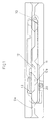
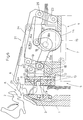
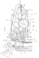
- a flat knitting machine comprises a pair of needle beds 1 (one of the pair only shown) arranged in an inverted-V form with their top ends facing each other and, having a multiplicity of knitting needles (not shown) disposed thereon in parallel arrangement, a plurality of sinkers 2 mounted between the knitting needles for swing movement about music wires 3 extending lengthwisely of the needle beds 1, and a couple of carriages 4 arranged for leftward and rightward movement along their respective needle beds 1, each carriage 4 being adapted to change its moving direction at a given point by means of a driver device.
- the carriage 4 is provided at upper left and right ends with a sinker swing action controller 5 for swing movement of the sinkers 2 and a stitch presser controller 7 for actuating a presser bar 6 respectively.
- the sinker swing action controller 5 and the stitch presser controller 7 are coupled to each other for linkage action.
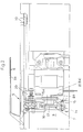
- the stitch presser controller 7 is driven by a driver mechanism 8.
- the sinker swing action controller 5, the stitch presser controller 7, and the driver mechanism 8 all are installed in a housing bracket 9.
- the housing bracket 9 has a sinker guide opening 9a arranged in a sinker-side wall thereof for clearing the lower end 2a of each sinker 2, as shown in Figs.1 to 4, which extends lengthwisely of the bracket 9.
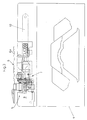
- the sinker swing action controller 5 which is also disposed on the sinker-side of the carriage 2, comprises a swing rod 10 coupled at one end to the housing bracket 9 for pivotal movement, a guide rod 11 having a length of about a half the swing rod 10 and extending along the upper end of the sinker guide opening 9a, a sinker engaging guide rod 12 arranged partially abutting on the guide rod 11 and extending along the center of the sinker guide opening 9a for moving into and out from the opening 9a, and a guide cam 13 having an L shape in cross section and arranged for engagement with a lower raised portion 12a of the sinker engaging guide rod 12.
- the sinker swing action controller 5 is actuated by the movement of the stitch presser controller 7, which will be described in more detail later, thus to swing the swing rod 10. Accordingly, as the swing rod 10 carries out a swing action, the guide rod 11, the sinker engaging guide rod 12, and the guide cam 13 are moved upward and downward thus actuating the sinkers 2. More specifically, the traveling of the carriage 4 triggers a combination movement of the guide rod 11, the sinker engaging guide rod 12, and the guide cam 13 which in turn actuates the lower end 2a of each sinker 2 held in the sinker guide opening 9a of the housing bracket 9 of the carriage 4 for swing action.
- the stitch presser controller 7 linked to the sinker swing action controller 5 for co-movement comprises a disk 14 fitted in eccentric arrangement onto a drive shaft 8b of a motor 8a of the driver mechanism 8, a connecting rod 15 having a rod portion 15a thereof and coupled to the disk 14, a swing connecting rod 16 fitted on the drive shaft 8b extending outward from the disk 14, another connecting rod 17 pivotably mounted at one end to the distal end of the swing connecting rod 16, a rotating support rod 18 pivoted at one end on the distal end of the rod portion 15a of the connecting rod 15 and at the the end, pivotably coupled to the housing bracket 9 for rotating movement, a swing rod 19 pivotably mounted at one end to the distal end of the rod portion 15a coaxially of the rotating support rod 18, a further connecting rod 20 pivotably mounted at one end to the other end of the swing support rod 19 and at the other end, fixedly coupled to the swing rod 10, and a swing mechanism 21 for directly actuating the presser bar 6 for swing action.
- the swing mechanism 21 comprises a couple of swing support rods 19 and 23 and a connecting action rod 24 for supporting the presser bar 6.
- the swing support rod 19 is pivotably mounted at one end to the sinker swing action controller 5 end of the housing bracket 9 and at the other end, pivotably coupled to the distal end of the connecting action rod 24.
- the other swing support rod 23 is disposed opposite to the sinker swing action controller 5 side and coupled at one end to the housing bracket 9 and at the other end, to the rear end of the connecting action rod 24 for pivotal linkage.
- the swing support rod 23 is coupled to the rear end of the connecting action rod 24 by a pivot pin 25 which is mounted on the distal end of the connecting rod 17.
- the presser bar 6 is formed in an approximately U shape and fixedly mounted at one end to the connecting rod 24.
- the presser bar 6 has a fabric press-down portion 6a thereof which extends along the top of the carriage 4 for moving into a toothed opening A between the two facing sinkers 2 of their respective needle beds 1 when they are opened.
- the fabric press-down portion 6a of the presser bar 6 supported by the connecting action rod 24 thus advances into the toothed opening A between the sinkers 2 and a fabric to be knitted is pressed downward from the toothed opening A as the carriage 4 travels in a given direction.
- the toothed opening A between the sinkers 2 which is closed in a normal state is opened and then, closed.
- the rotation of the drive shaft 8b of the motor 8a actuates the disk 14 which then allows the rod portion 15a of the connecting rod 15 to move towards the sinker swing action controller 5.
- the rotating support rod 22 and the swing rod 18 coaxially coupled to the rod portion 15a come aligned in upward and downward directions and the connecting rod 20 pivotably coupled to the rotating support rod 22 moves upward.
- the guide rod 11, sinker engaging guide rod 12, and guide cam 13 are then lifted up by the action of the connecting rod 10 of the sinker swing action controller 5 coupled to the connecting rod 20.
- the lower end 2a of each sinker 2 is turned upward about the music wire 3. Accordingly, the upper ends 2b of the two opposite sinkers 2 come close to each other thus closing the toothed opening A therebetween.
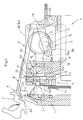
- the presser bar 6 is retracted from the toothed opening A between the sinkers 2 by the action of the stitch presser controller 7 as shown in Figs.4 to 7. More particularly, as the drive shaft 8b of the motor 8a rotates clockwise, the front end of the swing connecting rod 16 turns from the upper to the right in the drawings. The connecting action rod 24 is thus moved away from the sinker swing action controller 5 by the connecting rod 17 and the presser bar 6 supported by the connecting action rod 24 retracts from the toothed opening A between the sinkers 2. Simultaneously, the sinkers 2 are actuated by the action of the sinker swing action controller 5 synchronized with the stitch presser controller 7 to open the toothed opening A.
- the rod portion 15a of the connecting rod 15 moves away from the sinker swing action controller 5 as the drive shaft 8b of the motor 8a of the driver mechanism 8 is rotated clockwise.
- the movement of the connecting rod 19 causes the connecting rod 20 linked to the sinker swing action controller 5 to moves downward.
- the connecting rod 10 of the sinker swing action controller 5 lowers the guide rod 11, sinker engaging guide rod 12, and guide cam 13 throughout the housing bracket 9.
- the lower end 2a of each sinker 2 is lifted down by the downward movement of the guide rod 11. sinker engaging guide rod 12, and guide cam 13.
- the upper ends 2b of the two opposite sinkers 2 are actuated to open the toothed opening A therebetween.
- the swing rod 22 tilted as pulled at lower end towards the motor 8a is turned to a vertical position.
- This action of the swing rod 22 triggers via the connecting rod 20 the lifting of the guide rod 11, sinker engaging guide rod 12, and guide cam 13 in the housing bracket 9.
- the guide rod 11, sinker engaging guide rod 12, and guide cam 13 move upward, the lower end 2a of each sinker 2 is lifted up.
- the upper ends 2a of the two opposite sinkers 2 come close to each other to close the toothed opening A.
- the presser bar 6 has been retracted from the toothed opening A between the sinkers 2.
- the presser bar 6 advances into the toothed opening A between the two opposite sinkers 2 and presses down a knitted portion of fabric without disturbing the movement of the sinkers 2 associated with knitting of stitches.
Claims (1)
- Machine à tricoter rectiligne, caractérisée en ce qu'elle comprend:
une multiplicité d'aiguilles à tricoter placées sur les fontures d'aiguilles (1);
des platines cueuillantes (2) prévues entre les aiguilles à tricoter pour assurer un mouvement d'oscillation;
des chariots (4) prévus pour se diriger vers la gauche et vers la droite sur les fontures d'aiguilles (1) qui peuvent changer leur direction de déplacement en deux points donnés;
ledit chariot comportant un contrôleur (5) d'action d'oscillement de la platine cueillante et un contrôleur (7) de presseur de points, tous deux liés ensemble pour se déplacer en coopération;
ledit contrôleur de presseur de points couplé à un dispositif d'entraînement (8) et supportant une barre (6) de presseur prévue à proximité de l'extrémité supérieure du chariot;
ladite barre de presseur prévue pour se déplacer vers l'intérieur et vers l'extérieur d'une ouverture (A) dentée prévue entre les extrémités supérieures des deux fontures d'aiguilles (1) par l'action du contrôleur de presseur de points (7); et
ledit contrôleur d'action d'oscillement du presseur prévu pour actionner les platines cueillantes (2) se déplaçant en coopérant avec le contrôleur (7) de presseur de points, de sorte que lorsque le chariot (4) change sa direction de déplacement, la barre de presseur (6) et les platines cueillantes (2) sont actionnées à la fois pour assurer les actions d'avance et de retrait l'une par rapport à l'autre par le déplacement en coopération du contrôleur (5) de l'action d'oscillement de la platine cueillante et le contrôleur (7) du presseur de points.
Applications Claiming Priority (2)
| Application Number | Priority Date | Filing Date | Title |
|---|---|---|---|
| JP2222245A JPH0672347B2 (ja) | 1990-08-22 | 1990-08-22 | 揺動シンカーとプレッサーバーを有する横編機 |
| JP222245/90 | 1990-08-22 |
Publications (3)
| Publication Number | Publication Date |
|---|---|
| EP0472341A2 EP0472341A2 (fr) | 1992-02-26 |
| EP0472341A3 EP0472341A3 (en) | 1992-05-13 |
| EP0472341B1 true EP0472341B1 (fr) | 1995-10-11 |
Family
ID=16779376
Family Applications (1)
| Application Number | Title | Priority Date | Filing Date |
|---|---|---|---|
| EP91307414A Expired - Lifetime EP0472341B1 (fr) | 1990-08-22 | 1991-08-12 | Métier à tricoter rectiligne avec des platines oscillants et des barres de presse |
Country Status (6)
| Country | Link |
|---|---|
| US (1) | US5280712A (fr) |
| EP (1) | EP0472341B1 (fr) |
| JP (1) | JPH0672347B2 (fr) |
| KR (1) | KR0177825B1 (fr) |
| DE (1) | DE69113724T2 (fr) |
| ES (1) | ES2078451T3 (fr) |
Cited By (1)
| Publication number | Priority date | Publication date | Assignee | Title |
|---|---|---|---|---|
| CN103526448A (zh) * | 2013-11-01 | 2014-01-22 | 宁波慈星股份有限公司 | 针织横机中的毛刷支架机构 |
Families Citing this family (13)
| Publication number | Priority date | Publication date | Assignee | Title |
|---|---|---|---|---|
| DE4128016A1 (de) * | 1991-08-23 | 1993-02-25 | Stoll & Co H | Zweibettige flachstrickmaschine mit nadeln und platinen |
| JP2700204B2 (ja) * | 1992-12-15 | 1998-01-19 | 株式会社島精機製作所 | 横編機におけるシンカー装置 |
| JP4176108B2 (ja) | 2003-02-05 | 2008-11-05 | 株式会社島精機製作所 | 横編機におけるステッチプレッサー |
| JP4015978B2 (ja) * | 2003-09-02 | 2007-11-28 | 株式会社島精機製作所 | 可動糸ガイド部材を備えた横編機 |
| EP1790277B1 (fr) * | 2004-08-23 | 2018-11-21 | Olympus Corporation | Dispositif d'affichage d'image et programme d'affichage d'image |
| WO2007058272A1 (fr) * | 2005-11-16 | 2007-05-24 | Shima Seiki Manufacturing Limited | Bloc monte sur chariot pour metier a mailles cueillies |
| CN102296417A (zh) * | 2011-08-17 | 2011-12-28 | 常熟市国光机械有限公司 | 压脚毛刷连动系统 |
| US8468855B2 (en) * | 2011-09-16 | 2013-06-25 | Pai Lung Machinery Mill Co., Ltd. | Downward pressing mesh mechanism and sinker thereof for flat knitting machines |
| CN102747528B (zh) * | 2012-08-01 | 2013-09-25 | 常熟市国光机械有限公司 | 压圈动作控制系统 |
| JP5955180B2 (ja) * | 2012-09-24 | 2016-07-20 | 株式会社島精機製作所 | ステッチプレッサを備えた横編機及びその制御方法 |
| CN106319744A (zh) * | 2016-11-22 | 2017-01-11 | 飞虎科技有限公司 | 一种具有自锁功能的压圈装置 |
| KR102185883B1 (ko) | 2019-01-18 | 2020-12-02 | (주)대주메디테크엔지니어링 | 동심 다초점 구조의 트랜스듀서 모듈과 이를 이용한 초음파 시술장치 |
| EP3702503B1 (fr) * | 2019-02-27 | 2021-07-28 | Pai Lung Machinery Mill Co., Ltd. | Dispositif de press-maille de machine à tricoter rectiligne à position variable selon la taille d'écart |
Family Cites Families (14)
| Publication number | Priority date | Publication date | Assignee | Title |
|---|---|---|---|---|
| GB714087A (en) * | 1950-12-05 | 1954-08-25 | Liselotte Sailer | Improvements in warp knitting machines |
| CH416912A (de) * | 1963-11-15 | 1966-07-15 | Paliz Ag | Doppelbettstrickmaschine |
| GB1029400A (en) * | 1963-12-27 | 1966-05-11 | Cotton Ltd W | Improvements in or relating to straight bar knitting machines |
| DE1585217B1 (de) * | 1965-05-06 | 1970-08-27 | Mayer Textilmaschf | Kettenwirkmaschine mit Spitzennadeln |
| DE1585233B1 (de) * | 1966-03-10 | 1970-10-22 | Mayer Textilmaschf | Kettenwirkmaschine mit Spitzennadeln |
| GB1326540A (en) * | 1969-12-23 | 1973-08-15 | Courtaulds Ltd | Knitting machines |
| US3685317A (en) * | 1970-11-19 | 1972-08-22 | Billi Spa | Device for tensioning stitches being formed in hosiery dual-bed flat machines |
| US4027504A (en) * | 1976-07-12 | 1977-06-07 | Robert Dietschy | Stitch presser for knitting machine |
| SU631109A1 (ru) * | 1976-01-23 | 1978-11-05 | Fedorov Vladimir A | Привод шпинделей хлопкоуборочного апппрата |
| DE3114405C2 (de) * | 1981-04-09 | 1983-01-20 | Karl Mayer Textil-Maschinen-Fabrik Gmbh, 6053 Obertshausen | Nähwirkmaschine |
| JPS57183451A (en) * | 1981-04-28 | 1982-11-11 | Shima Idea Center | Knitted cloth press apparatus in v bed traverse knitting machine |
| IT212179Z2 (it) * | 1987-10-02 | 1989-07-04 | Emm Srl | Apparato per il supporto,il comando ed il controllo di organi pressamaglia-battimaglia in una macchina rettilinea per maglieria |
| EP0347011A1 (fr) * | 1988-06-13 | 1989-12-20 | UNIVERSAL Maschinenfabrik Dr. Rudolf Schieber GmbH & Co. KG | Métier à tricoter rectiligne |
| JPH038841A (ja) * | 1989-06-02 | 1991-01-16 | Shima Seiki Seisakusho:Kk | Vベツド横編機における編地プレツサー |
-
1990
- 1990-08-22 JP JP2222245A patent/JPH0672347B2/ja not_active Expired - Fee Related
-
1991
- 1991-08-05 KR KR1019910013499A patent/KR0177825B1/ko not_active IP Right Cessation
- 1991-08-12 EP EP91307414A patent/EP0472341B1/fr not_active Expired - Lifetime
- 1991-08-12 ES ES91307414T patent/ES2078451T3/es not_active Expired - Lifetime
- 1991-08-12 DE DE69113724T patent/DE69113724T2/de not_active Expired - Lifetime
- 1991-08-15 US US07/745,291 patent/US5280712A/en not_active Expired - Lifetime
Cited By (2)
| Publication number | Priority date | Publication date | Assignee | Title |
|---|---|---|---|---|
| CN103526448A (zh) * | 2013-11-01 | 2014-01-22 | 宁波慈星股份有限公司 | 针织横机中的毛刷支架机构 |
| CN103526448B (zh) * | 2013-11-01 | 2014-12-31 | 宁波慈星股份有限公司 | 针织横机中的毛刷支架机构 |
Also Published As
| Publication number | Publication date |
|---|---|
| KR0177825B1 (ko) | 1999-02-01 |
| EP0472341A3 (en) | 1992-05-13 |
| DE69113724D1 (de) | 1995-11-16 |
| JPH0672347B2 (ja) | 1994-09-14 |
| EP0472341A2 (fr) | 1992-02-26 |
| KR920004632A (ko) | 1992-03-27 |
| US5280712A (en) | 1994-01-25 |
| ES2078451T3 (es) | 1995-12-16 |
| JPH04108143A (ja) | 1992-04-09 |
| DE69113724T2 (de) | 1996-03-21 |
Similar Documents
| Publication | Publication Date | Title |
|---|---|---|
| EP0472341B1 (fr) | Métier à tricoter rectiligne avec des platines oscillants et des barres de presse | |
| KR100249119B1 (ko) | 눈옮김장치를 가진 횡편기 | |
| EP1867768B1 (fr) | Procede de tricotage d un tissu cylindrique dans un metier a tricoter trame et metier a tricoter trame | |
| US7207194B2 (en) | Weft knitting machine with movable yarn guide member | |
| EP0435690B1 (fr) | Dispositif de platines pour des métiers à tricoter rectilignes | |
| CN100519866C (zh) | 横机的喂纱装置及横机的喂纱方法 | |
| JP2602156B2 (ja) | 横編機の編地プレッサー | |
| KR100243957B1 (ko) | 셋업장치를 구비한 횡편직기 | |
| JP3463210B2 (ja) | 横編機のカム用移動装置 | |
| JPH0366415B2 (fr) | ||
| JP2646317B2 (ja) | 編針及びシンカを持つ2針床横編機 | |
| JPH0474463B2 (fr) | ||
| US4027505A (en) | Circular knitting machine with disengaging positive yarn feeding means | |
| JPH03206161A (ja) | 横編機におけるシンカー装置 | |
| US4033150A (en) | Circular knitting machine for producing detachable strips of knitted fabric | |
| JP4017737B2 (ja) | 糸端保持手段を備えた多針ミシン | |
| US7059157B2 (en) | Stitch presser in a weft knitting machine | |
| EP0604164A2 (fr) | Procédé pour le tricotage d'un dessin à croisement et dispositif pour le tricotage d'un dessin à croisement à un métier à tricoter rectiligne | |
| CN214529495U (zh) | 一种限位结构沉降片及针织横机 | |
| CN220099325U (zh) | 横机的针织物压片装置 | |
| EP0385154A1 (fr) | Dispositif d'étirage mécanique | |
| JPH03294549A (ja) | 横式メリヤス編機における編針増減装置 | |
| JP2845506B2 (ja) | 横編地の編成方法 | |
| SU971956A1 (ru) | Каретка плосков зальной машины | |
| JPH0657902B2 (ja) | 編地編成方法及び前記編地編成方法を実施するためのキャリッジ装置 |
Legal Events
| Date | Code | Title | Description |
|---|---|---|---|
| PUAI | Public reference made under article 153(3) epc to a published international application that has entered the european phase |
Free format text: ORIGINAL CODE: 0009012 |
|
| AK | Designated contracting states |
Kind code of ref document: A2 Designated state(s): CH DE ES FR GB IT LI |
|
| PUAL | Search report despatched |
Free format text: ORIGINAL CODE: 0009013 |
|
| AK | Designated contracting states |
Kind code of ref document: A3 Designated state(s): CH DE ES FR GB IT LI |
|
| 17P | Request for examination filed |
Effective date: 19920706 |
|
| 17Q | First examination report despatched |
Effective date: 19950130 |
|
| ITF | It: translation for a ep patent filed |
Owner name: INTERPATENT ST.TECN. BREV. |
|
| GRAA | (expected) grant |
Free format text: ORIGINAL CODE: 0009210 |
|
| AK | Designated contracting states |
Kind code of ref document: B1 Designated state(s): CH DE ES FR GB IT LI |
|
| REF | Corresponds to: |
Ref document number: 69113724 Country of ref document: DE Date of ref document: 19951116 |
|
| REG | Reference to a national code |
Ref country code: ES Ref legal event code: FG2A Ref document number: 2078451 Country of ref document: ES Kind code of ref document: T3 |
|
| REG | Reference to a national code |
Ref country code: CH Ref legal event code: NV Representative=s name: E. BLUM & CO. PATENTANWAELTE |
|
| ET | Fr: translation filed | ||
| PLBE | No opposition filed within time limit |
Free format text: ORIGINAL CODE: 0009261 |
|
| STAA | Information on the status of an ep patent application or granted ep patent |
Free format text: STATUS: NO OPPOSITION FILED WITHIN TIME LIMIT |
|
| 26N | No opposition filed | ||
| REG | Reference to a national code |
Ref country code: GB Ref legal event code: IF02 |
|
| PGFP | Annual fee paid to national office [announced via postgrant information from national office to epo] |
Ref country code: ES Payment date: 20070926 Year of fee payment: 17 |
|
| REG | Reference to a national code |
Ref country code: CH Ref legal event code: PFA Owner name: SHIMA SEIKI MFG, LTD Free format text: SHIMA SEIKI MFG, LTD#85, SAKATA#WAKAYAMA-SHI/WAKAYAMA-KEN (JP) -TRANSFER TO- SHIMA SEIKI MFG, LTD#85, SAKATA#WAKAYAMA-SHI/WAKAYAMA-KEN (JP) |
|
| PGFP | Annual fee paid to national office [announced via postgrant information from national office to epo] |
Ref country code: FR Payment date: 20070808 Year of fee payment: 17 |
|
| REG | Reference to a national code |
Ref country code: FR Ref legal event code: ST Effective date: 20090430 |
|
| PG25 | Lapsed in a contracting state [announced via postgrant information from national office to epo] |
Ref country code: FR Free format text: LAPSE BECAUSE OF NON-PAYMENT OF DUE FEES Effective date: 20080901 |
|
| REG | Reference to a national code |
Ref country code: ES Ref legal event code: FD2A Effective date: 20080813 |
|
| PGFP | Annual fee paid to national office [announced via postgrant information from national office to epo] |
Ref country code: DE Payment date: 20090806 Year of fee payment: 19 Ref country code: CH Payment date: 20090814 Year of fee payment: 19 Ref country code: GB Payment date: 20090812 Year of fee payment: 19 |
|
| PG25 | Lapsed in a contracting state [announced via postgrant information from national office to epo] |
Ref country code: ES Free format text: LAPSE BECAUSE OF NON-PAYMENT OF DUE FEES Effective date: 20080813 |
|
| PGFP | Annual fee paid to national office [announced via postgrant information from national office to epo] |
Ref country code: IT Payment date: 20090814 Year of fee payment: 19 |
|
| REG | Reference to a national code |
Ref country code: CH Ref legal event code: PL |
|
| GBPC | Gb: european patent ceased through non-payment of renewal fee |
Effective date: 20100812 |
|
| PG25 | Lapsed in a contracting state [announced via postgrant information from national office to epo] |
Ref country code: CH Free format text: LAPSE BECAUSE OF NON-PAYMENT OF DUE FEES Effective date: 20100831 Ref country code: LI Free format text: LAPSE BECAUSE OF NON-PAYMENT OF DUE FEES Effective date: 20100831 |
|
| PG25 | Lapsed in a contracting state [announced via postgrant information from national office to epo] |
Ref country code: IT Free format text: LAPSE BECAUSE OF NON-PAYMENT OF DUE FEES Effective date: 20100812 |
|
| REG | Reference to a national code |
Ref country code: DE Ref legal event code: R119 Ref document number: 69113724 Country of ref document: DE Effective date: 20110301 |
|
| PG25 | Lapsed in a contracting state [announced via postgrant information from national office to epo] |
Ref country code: DE Free format text: LAPSE BECAUSE OF NON-PAYMENT OF DUE FEES Effective date: 20110301 |
|
| PG25 | Lapsed in a contracting state [announced via postgrant information from national office to epo] |
Ref country code: GB Free format text: LAPSE BECAUSE OF NON-PAYMENT OF DUE FEES Effective date: 20100812 |