EP0469483A2 - Verfahren zum Haspelwechsel beim kontinuierlichen Warmwalzen und Vorrichtung dafür - Google Patents
Verfahren zum Haspelwechsel beim kontinuierlichen Warmwalzen und Vorrichtung dafür Download PDFInfo
- Publication number
- EP0469483A2 EP0469483A2 EP91112604A EP91112604A EP0469483A2 EP 0469483 A2 EP0469483 A2 EP 0469483A2 EP 91112604 A EP91112604 A EP 91112604A EP 91112604 A EP91112604 A EP 91112604A EP 0469483 A2 EP0469483 A2 EP 0469483A2
- Authority
- EP
- European Patent Office
- Prior art keywords
- coiler
- hot rolling
- steel strip
- pinch rolls
- strip
- Prior art date
- Legal status (The legal status is an assumption and is not a legal conclusion. Google has not performed a legal analysis and makes no representation as to the accuracy of the status listed.)
- Withdrawn
Links
Images


Classifications
-
- B—PERFORMING OPERATIONS; TRANSPORTING
- B21—MECHANICAL METAL-WORKING WITHOUT ESSENTIALLY REMOVING MATERIAL; PUNCHING METAL
- B21D—WORKING OR PROCESSING OF SHEET METAL OR METAL TUBES, RODS OR PROFILES WITHOUT ESSENTIALLY REMOVING MATERIAL; PUNCHING METAL
- B21D1/00—Straightening, restoring form or removing local distortions of sheet metal or specific articles made therefrom; Stretching sheet metal combined with rolling
-
- B—PERFORMING OPERATIONS; TRANSPORTING
- B21—MECHANICAL METAL-WORKING WITHOUT ESSENTIALLY REMOVING MATERIAL; PUNCHING METAL
- B21C—MANUFACTURE OF METAL SHEETS, WIRE, RODS, TUBES OR PROFILES, OTHERWISE THAN BY ROLLING; AUXILIARY OPERATIONS USED IN CONNECTION WITH METAL-WORKING WITHOUT ESSENTIALLY REMOVING MATERIAL
- B21C47/00—Winding-up, coiling or winding-off metal wire, metal band or other flexible metal material characterised by features relevant to metal processing only
- B21C47/02—Winding-up or coiling
- B21C47/04—Winding-up or coiling on or in reels or drums, without using a moving guide
-
- B—PERFORMING OPERATIONS; TRANSPORTING
- B21—MECHANICAL METAL-WORKING WITHOUT ESSENTIALLY REMOVING MATERIAL; PUNCHING METAL
- B21B—ROLLING OF METAL
- B21B15/00—Arrangements for performing additional metal-working operations specially combined with or arranged in, or specially adapted for use in connection with, metal-rolling mills
- B21B2015/0057—Coiling the rolled product
-
- B—PERFORMING OPERATIONS; TRANSPORTING
- B21—MECHANICAL METAL-WORKING WITHOUT ESSENTIALLY REMOVING MATERIAL; PUNCHING METAL
- B21B—ROLLING OF METAL
- B21B39/00—Arrangements for moving, supporting, or positioning work, or controlling its movement, combined with or arranged in, or specially adapted for use in connection with, metal-rolling mills
- B21B39/006—Pinch roll sets
Definitions
- This invention relates to a process for coiler drum alternation in incessant hot rolling of steel strip and to an apparatus therefor.
- incessant hot rolling herein is meant a system in which preceding ones and succeeding ones of rough rolled slabs are joined together one after another by a flying welder on the entry side of a finishing hot rolling mill, and the joined slabs are subjected continually to finish hot rolling to produce a steel strip.
- the traveling speed of the steel strip has been controlled to or below a predetermined value until the leading end of the strip starts being wrapped around the mandrel of the coiler, so as to prevent the leading end portion from being lifted while traveling.
- the batch rolling system has the drawback of varied rolling speeds and low rolling efficiency.
- the batch rolling system involves waste of time in, for example, pepara- tory operations between the rolling of a preceding rolling stock and the rolling of the following rolling stock, leading to low efficiency in using the equipment.
- the finish rolled products are liable to have poor shape at the head and tail ends thereof, resulting in a low production efficiency, and so on.
- incessant hot rolling is adopted.
- the steel strip obtained by continual rolling of joined slabs is cut up by a flying shear into lengths of strip corresponding to the initial slabs, followed by coiling by coilers. It is necessary in this case to change over the path of the steel strip so that the leading ends of the cut lengths of strip are guided to be taken up on the respective coiler drums.
- Techniques for such coiler drum ternation are disclosed in Japanese Patent Application Laid-Open (KOKAI) No. 61-014003 (1986) (Process for Down-Coiler Alternation in Inceimpuls Hot Rolling) and Japanese Patent Application Laid-Open (KOKAI) No. 61-119326 (1986) (Gate Device for RollingLine Alternation).
- a deflector disposed on the entry side of coiler rolls is moved up and down to achieve alternation of coilers.
- the up-down motion of the deflector may flaw the steel strip.
- the deflector is provided with auxiliary rollers. Since the auxiliary rollers are to be arranged in a limited space, however, the rollers should be small in diameter and, due to the small roller diameter, a slight deviation in the position of contact of the roller with the steel strip can render the strip guiding direction unstable, making it impossible to coil the strip.
- each coiler is provided with a main and an auxiliary set of pinch rolls, which are operated to achieve coiler drum alternation. This technique requires a complicated mechanism.
- this invention makes an improvement on the alternation of coiler drums for a traveling steel strip in incessant hot rolling, by adopting the following process.
- the process for coiler drum alternation in incessant hot rolling comprises the steps of oscillating upper and lower tillable pinch rolls disposed on the exit side of a shear, thereby changing the direction of the steel strip so that a leading end formed upon cutting the strip will be directed toward the coiler drum to be used next, and cutting the steel strip.
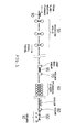
- Figure 5 illustrates the entire steps carried out in a hot rolling line.
- a steel slab 90 is rough rolled by hot roughing mills 50, to become a sheet bar 95.
- the sheet bar 95 is finish rolled by hot finishing stands 60 into an elongate steel strip 100.
- the sheet bars 50 are finish rolled one by one, and the resultant steel strips are coiled by coilers 30 one by one (each strip being coiled on one of coiler drums). After one steel strip is taken up on one coiler drum, in the conventional batch rolling system, there is sufficient time for such a preparatory operation as to enable the next steel strip to be coiled on another coiler drum.
- a welder 70 for joining the sheet bars 95 is provided between the roughing mills 50 and the finishing stands 60, so as to joint the leading end of the succeeding sheet bar to the tail end of the preceding sheet bar. Therefore, the hot finishing stands 60 performs continual rolling of a multiplicity of sheet bars 95 joined together. Since the joined body of sheet bars 95 finish rolled continually in this manner has discontinuity only at the foremost and backmost ends, it is possible to carry out high-speed finish rolling, without any complicated modification of rolling speed.
- FIG. 4 shows an apparatus according to the prior art, in which pinch rolls 40, 42 can be moved farther apart, and a deflector 44 capable of being moved up and down is provided on the entry side of coiler drums 30a, 30b so as to change the traveling direction of the steel strip 100.
- the deflector 44 is provided with auxiliary rollers 48 small in diameter. In this conventional apparatus, a slight deviation in the position of contact of the strip 100 with the roller 48 can render the strip guiding direction unstable, making it impossible to coil the strip.
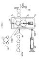
- Figure 1 is an illustration of the apparatus for coiler drum alternation according to this invention.
- rough-rolled sheet bars are jointed end to end at a position on the entry side of the finishing stands, the jointed sheet bars are continually hot rolled in the finishing stands, the resultant steel strip is cut up on the entry side of coilers, and the cut lengths of strip are successively coiled, in an alternating manner, on a plurality of coilers arranged in series.
- upper and lower pinch rolls 10 and 12 are placed in a housing 14.
- the housing 14 is so designed as to be tilted by a hydraulic cylinder 16.
- the housing 14 is tilted by the hydraulic cylinder 16 so that the center line 22 passing through the centers of the upper and lower pinch rolls 10, 12 is tilted as indicated by 22a, and a deflector 18 is directed to the side of the coiler 30, whereby the strip 100 is coiled.
- the housing 14 is returned into the solid-line position in Figure 1, and the deflector 18 into the position for directing downstream.
- Figure 2 shows the changeover from a coiler 30b on the downstream side to a coiler 30a on the upstream side.
- a housing 14 on the upstream side is tilted so that the center line passing through the centers of the upper and lower pinch rolls 10a, 12a is tilted, the upstream-side coiler 30a is set ready for coiling, and the steel strip 100 is cut by the shear 80.
- the upper and lower pinch rolls 10b, 12b of the downstream-side coiler 30b may be in the non- tilted condition. It is thereby possible to maintain a tail end portion of the steel strip 100b securely by the pinch rolls 10b, 12b until the coiling of the strip 100b is finished, and to obtain a better coil form.
- Figure 3 shows a changeover from the coiler 30a on the upstream side to the coiler 30b on the downstream side.
- the housing 14b on the downstream side is tilted so that the center line passing through the centers of the upper and lower pinch rolls 10b, 12b of the downstream-side coiler 14b is tilted, and the downstream-side coiler 30b is set ready for coiling.
- the center line passing through the centers of the upper and lower pinch rolls 10a, 12a of the upstream-side coiler 30a is kept untilted.
- the steel strip 100 is cut by the shear while the upper pinch roll 10a of the upstream-side coiler 30a is thus prevented from exerting a downward bending force on the succeeding portion of strip.
- the succeeding portion of strip is moved straight ahead to be caught by the pinch rolls 10b, 12b on the downstream side, and is wrapped around the downstream-side coiler 30b.
Landscapes
- Engineering & Computer Science (AREA)
- Mechanical Engineering (AREA)
- Winding, Rewinding, Material Storage Devices (AREA)
- Metal Rolling (AREA)
Applications Claiming Priority (2)
| Application Number | Priority Date | Filing Date | Title |
|---|---|---|---|
| JP201309/90 | 1990-07-31 | ||
| JP2201309A JPH0489135A (ja) | 1990-07-31 | 1990-07-31 | エンドレス熱間圧延における巻取機の切換方法 |
Publications (2)
| Publication Number | Publication Date |
|---|---|
| EP0469483A2 true EP0469483A2 (de) | 1992-02-05 |
| EP0469483A3 EP0469483A3 (en) | 1992-04-08 |
Family
ID=16438871
Family Applications (1)
| Application Number | Title | Priority Date | Filing Date |
|---|---|---|---|
| EP19910112604 Withdrawn EP0469483A3 (en) | 1990-07-31 | 1991-07-26 | Process for coiler drum alternation in incessant hot rolling and apparatus therefor |
Country Status (5)
| Country | Link |
|---|---|
| EP (1) | EP0469483A3 (de) |
| JP (1) | JPH0489135A (de) |
| KR (1) | KR950001807B1 (de) |
| CN (1) | CN1034400C (de) |
| CA (1) | CA2048127C (de) |
Cited By (4)
| Publication number | Priority date | Publication date | Assignee | Title |
|---|---|---|---|---|
| EP0790084A3 (de) * | 1996-02-14 | 1998-04-29 | Sms Schloemann-Siemag Aktiengesellschaft | Haspelanlage für Bänder |
| KR100453435B1 (ko) * | 1996-02-14 | 2006-01-27 | 에스엠에스 데마그 악티엔게젤샤프트 | 스트립용권취장치 |
| DE102008016314A1 (de) | 2007-03-28 | 2008-10-02 | Sms Demag Ag | Verfahren und Vorrichtung zum Aufwickeln von Warmband |
| CN111032241A (zh) * | 2017-08-18 | 2020-04-17 | Posco公司 | 卷取装置 |
Families Citing this family (10)
| Publication number | Priority date | Publication date | Assignee | Title |
|---|---|---|---|---|
| US5769219A (en) * | 1995-06-08 | 1998-06-23 | Shimel; Jerry W. | Beverage storage apparatus for use with a golf bag |
| DE10208964A1 (de) * | 2002-02-28 | 2003-09-18 | Sms Demag Ag | Umlenkeinrichtung für ein Band in einer Haspelanlage |
| DE10258499A1 (de) * | 2002-12-14 | 2004-07-01 | Sms Demag Ag | Umlenkvorrichtung einer Haspelanlage zum Aufhaspeln von Bändern |
| DE102006029858A1 (de) * | 2006-06-28 | 2008-01-03 | Sms Demag Ag | Verfahren und Vorrichtung zum Aufwickeln eines metallischen Bandes |
| CN102513409A (zh) * | 2011-12-24 | 2012-06-27 | 中国重型机械研究院有限公司 | 一种冷连轧机组带材快速活门系统 |
| CN105059998A (zh) * | 2015-08-12 | 2015-11-18 | 安徽江威精密制造有限公司 | 角度变换装置 |
| CN107282693A (zh) * | 2017-06-29 | 2017-10-24 | 广东含元工业技术有限公司 | 一种金属带材的液压卷筒结构 |
| CN112893515B (zh) * | 2021-03-03 | 2022-08-09 | 烟台孚信达双金属股份有限公司 | 一种棒材蚊香盘层叠式收卷机 |
| CN114589214B (zh) * | 2022-02-28 | 2024-10-01 | 首钢京唐钢铁联合有限责任公司 | 一种下夹送辊缠辊处理方法和装置 |
| CN115106398B (zh) * | 2022-07-28 | 2023-10-27 | 射洪县才伦建材有限责任公司 | 一种用于钢筋生产的分流式盘螺收卷加工设备 |
Citations (4)
| Publication number | Priority date | Publication date | Assignee | Title |
|---|---|---|---|---|
| AT218993B (de) * | 1959-11-27 | 1962-01-10 | Siemens Ag | Digitale wegabhängige Steuereinrichtung |
| JPS6114003A (ja) * | 1984-06-29 | 1986-01-22 | Sumitomo Metal Ind Ltd | 連続熱間圧延ダウンコイラ切換方法 |
| GB2163689A (en) * | 1984-08-31 | 1986-03-05 | Davy Mckee | Hot rolling metal strip |
| JPS61119326A (ja) * | 1984-11-16 | 1986-06-06 | Mitsubishi Heavy Ind Ltd | 圧延ライン切換えゲ−ト装置 |
Family Cites Families (8)
| Publication number | Priority date | Publication date | Assignee | Title |
|---|---|---|---|---|
| JPH01250246A (ja) * | 1987-09-21 | 1989-10-05 | Nippon Petrochem Co Ltd | 医療用トレー |
| JP2003265584A (ja) * | 2002-03-15 | 2003-09-24 | Yamato Sanki:Kk | 医療施設と受託業者との医療機器資材の滅菌業務の循環システム |
| JP3947686B2 (ja) * | 2002-06-11 | 2007-07-25 | オリンパス株式会社 | 医療用具のリユース管理システム及びコンピュータによる医療用具のリユース管理方法 |
| JP4338464B2 (ja) * | 2003-07-11 | 2009-10-07 | Hoya株式会社 | 内視鏡用洗浄用具 |
| US7918896B2 (en) * | 2004-09-15 | 2011-04-05 | Wright Medical Technology, Inc. | Unitary acetabular cup prosthesis with extension for deficient acetabulum |
| AU2007297546B9 (en) * | 2006-09-21 | 2013-06-20 | Spinecore, Inc. | Intervertebral disc implants and tooling |
| US8740912B2 (en) * | 2008-02-27 | 2014-06-03 | Ilion Medical Llc | Tools for performing less invasive orthopedic joint procedures |
| EP2339982B1 (de) * | 2008-10-21 | 2012-09-12 | Medicart International Limited | Kit zur aufbewahrung und beförderung von medizinischen geräten |
-
1990
- 1990-07-31 JP JP2201309A patent/JPH0489135A/ja active Pending
-
1991
- 1991-07-26 EP EP19910112604 patent/EP0469483A3/en not_active Withdrawn
- 1991-07-30 CA CA002048127A patent/CA2048127C/en not_active Expired - Fee Related
- 1991-07-31 KR KR1019910013156A patent/KR950001807B1/ko not_active IP Right Cessation
- 1991-07-31 CN CN91105632A patent/CN1034400C/zh not_active Expired - Fee Related
Patent Citations (4)
| Publication number | Priority date | Publication date | Assignee | Title |
|---|---|---|---|---|
| AT218993B (de) * | 1959-11-27 | 1962-01-10 | Siemens Ag | Digitale wegabhängige Steuereinrichtung |
| JPS6114003A (ja) * | 1984-06-29 | 1986-01-22 | Sumitomo Metal Ind Ltd | 連続熱間圧延ダウンコイラ切換方法 |
| GB2163689A (en) * | 1984-08-31 | 1986-03-05 | Davy Mckee | Hot rolling metal strip |
| JPS61119326A (ja) * | 1984-11-16 | 1986-06-06 | Mitsubishi Heavy Ind Ltd | 圧延ライン切換えゲ−ト装置 |
Non-Patent Citations (2)
| Title |
|---|
| PATENT ABSTRACTS OF JAPAN vol. 10, no. 159, 7 June 1986; & JP - A - 61014003 (SUMITOMO KINZOKU KOGYO KK) 22.01.1986 * |
| PATENT ABSTRACTS OF JAPAN vol. 10, no. 307, 18 October 1986; & JP - A - 61119326 (MITSUBISHI) 06.06.1986 * |
Cited By (8)
| Publication number | Priority date | Publication date | Assignee | Title |
|---|---|---|---|---|
| EP0790084A3 (de) * | 1996-02-14 | 1998-04-29 | Sms Schloemann-Siemag Aktiengesellschaft | Haspelanlage für Bänder |
| US5966978A (en) * | 1996-02-14 | 1999-10-19 | Sms Schloemann-Siemag Aktiengesellschaft | Reeling unit for strip |
| CN1081495C (zh) * | 1996-02-14 | 2002-03-27 | Sms舒路曼-斯玛公司 | 用于钢带的卷取机装置 |
| KR100453435B1 (ko) * | 1996-02-14 | 2006-01-27 | 에스엠에스 데마그 악티엔게젤샤프트 | 스트립용권취장치 |
| DE102008016314A1 (de) | 2007-03-28 | 2008-10-02 | Sms Demag Ag | Verfahren und Vorrichtung zum Aufwickeln von Warmband |
| US9238259B2 (en) | 2007-03-28 | 2016-01-19 | Sms Group Gmbh | Method and device for winding hot-rolled strip |
| CN111032241A (zh) * | 2017-08-18 | 2020-04-17 | Posco公司 | 卷取装置 |
| EP3670013A4 (de) * | 2017-08-18 | 2020-08-26 | Posco | Aufwickelvorrichtung |
Also Published As
| Publication number | Publication date |
|---|---|
| KR950001807B1 (ko) | 1995-03-03 |
| KR920002243A (ko) | 1992-02-28 |
| EP0469483A3 (en) | 1992-04-08 |
| CA2048127A1 (en) | 1992-02-01 |
| CN1034400C (zh) | 1997-04-02 |
| CA2048127C (en) | 1997-01-21 |
| CN1060798A (zh) | 1992-05-06 |
| JPH0489135A (ja) | 1992-03-23 |
Similar Documents
| Publication | Publication Date | Title |
|---|---|---|
| RU2216416C2 (ru) | Установка и способ горячей прокатки плоского проката | |
| EP0469483A2 (de) | Verfahren zum Haspelwechsel beim kontinuierlichen Warmwalzen und Vorrichtung dafür | |
| EP0968774B1 (de) | Verfahren zur herstellung eines warmgewalzten stahlbandes | |
| JPS61259804A (ja) | 仕上げ前帯材を熱間広幅帯材に圧延するための方法及び装置 | |
| US4123011A (en) | Coil unwind and wind-up method and apparatus therefor | |
| US3834207A (en) | Method and apparatus for forming an accurately dimensioned metal strip having varying thickness | |
| US3700157A (en) | Apparatus for feeding strip-like material to a processing apparatus | |
| EP3208005B1 (de) | Kombinierte schweiss- und walzanlage für metallbänder | |
| US4491006A (en) | Method and apparatus for coiling strip between the roughing train and the finishing train | |
| JPH04105701A (ja) | 連続熱間薄板圧延方法及び設備 | |
| CA2229255C (en) | Long slab rolling process and apparatus | |
| JP4022103B2 (ja) | 熱間圧延ラインにおける熱間仕上げ圧延機の出側ストリップの速度制御方法 | |
| JP2002219501A (ja) | 熱間鋼帯の製造方法及びその製造設備 | |
| JP2820520B2 (ja) | エンドレス熱間圧延における巻取機の切換方法 | |
| US5767475A (en) | Hot rolling method | |
| JP2003025015A (ja) | 鋼帯の巻取り方法 | |
| JPH04228217A (ja) | 熱延鋼帯の搬送方向切換装置と巻取り装置 | |
| JP3292608B2 (ja) | エンドレス熱延鋼帯の圧延切断方法 | |
| JPH09150201A (ja) | 薄板連続処理設備 | |
| US5804790A (en) | Hot rolling method | |
| JPH06170411A (ja) | 鋼片の連続熱間圧延設備 | |
| JP2000254704A (ja) | 板厚プレスによる熱延鋼板の製造方法及び製造装置 | |
| SU1479150A1 (ru) | Способ гор чей прокатки полос и листов | |
| JPH1094801A (ja) | 熱間スラブの幅プレス方法 | |
| JP2001079605A (ja) | 異幅ストリップの切断方法 |
Legal Events
| Date | Code | Title | Description |
|---|---|---|---|
| PUAI | Public reference made under article 153(3) epc to a published international application that has entered the european phase |
Free format text: ORIGINAL CODE: 0009012 |
|
| AK | Designated contracting states |
Kind code of ref document: A2 Designated state(s): DE FR GB IT |
|
| PUAL | Search report despatched |
Free format text: ORIGINAL CODE: 0009013 |
|
| AK | Designated contracting states |
Kind code of ref document: A3 Designated state(s): DE FR GB IT |
|
| 17P | Request for examination filed |
Effective date: 19920717 |
|
| 17Q | First examination report despatched |
Effective date: 19930909 |
|
| STAA | Information on the status of an ep patent application or granted ep patent |
Free format text: STATUS: THE APPLICATION IS DEEMED TO BE WITHDRAWN |
|
| 18D | Application deemed to be withdrawn |
Effective date: 19940913 |