EP0469483A2 - Process for coiler drum alternation in incessant hot rolling and apparatus therefor - Google Patents
Process for coiler drum alternation in incessant hot rolling and apparatus therefor Download PDFInfo
- Publication number
- EP0469483A2 EP0469483A2 EP91112604A EP91112604A EP0469483A2 EP 0469483 A2 EP0469483 A2 EP 0469483A2 EP 91112604 A EP91112604 A EP 91112604A EP 91112604 A EP91112604 A EP 91112604A EP 0469483 A2 EP0469483 A2 EP 0469483A2
- Authority
- EP
- European Patent Office
- Prior art keywords
- coiler
- hot rolling
- steel strip
- pinch rolls
- strip
- Prior art date
- Legal status (The legal status is an assumption and is not a legal conclusion. Google has not performed a legal analysis and makes no representation as to the accuracy of the status listed.)
- Withdrawn
Links
Images


Classifications
-
- B—PERFORMING OPERATIONS; TRANSPORTING
- B21—MECHANICAL METAL-WORKING WITHOUT ESSENTIALLY REMOVING MATERIAL; PUNCHING METAL
- B21D—WORKING OR PROCESSING OF SHEET METAL OR METAL TUBES, RODS OR PROFILES WITHOUT ESSENTIALLY REMOVING MATERIAL; PUNCHING METAL
- B21D1/00—Straightening, restoring form or removing local distortions of sheet metal or specific articles made therefrom; Stretching sheet metal combined with rolling
-
- B—PERFORMING OPERATIONS; TRANSPORTING
- B21—MECHANICAL METAL-WORKING WITHOUT ESSENTIALLY REMOVING MATERIAL; PUNCHING METAL
- B21C—MANUFACTURE OF METAL SHEETS, WIRE, RODS, TUBES OR PROFILES, OTHERWISE THAN BY ROLLING; AUXILIARY OPERATIONS USED IN CONNECTION WITH METAL-WORKING WITHOUT ESSENTIALLY REMOVING MATERIAL
- B21C47/00—Winding-up, coiling or winding-off metal wire, metal band or other flexible metal material characterised by features relevant to metal processing only
- B21C47/02—Winding-up or coiling
- B21C47/04—Winding-up or coiling on or in reels or drums, without using a moving guide
-
- B—PERFORMING OPERATIONS; TRANSPORTING
- B21—MECHANICAL METAL-WORKING WITHOUT ESSENTIALLY REMOVING MATERIAL; PUNCHING METAL
- B21B—ROLLING OF METAL
- B21B15/00—Arrangements for performing additional metal-working operations specially combined with or arranged in, or specially adapted for use in connection with, metal-rolling mills
- B21B2015/0057—Coiling the rolled product
-
- B—PERFORMING OPERATIONS; TRANSPORTING
- B21—MECHANICAL METAL-WORKING WITHOUT ESSENTIALLY REMOVING MATERIAL; PUNCHING METAL
- B21B—ROLLING OF METAL
- B21B39/00—Arrangements for moving, supporting, or positioning work, or controlling its movement, combined with or arranged in, or specially adapted for use in connection with, metal-rolling mills
- B21B39/006—Pinch roll sets
Definitions
- This invention relates to a process for coiler drum alternation in incessant hot rolling of steel strip and to an apparatus therefor.
- incessant hot rolling herein is meant a system in which preceding ones and succeeding ones of rough rolled slabs are joined together one after another by a flying welder on the entry side of a finishing hot rolling mill, and the joined slabs are subjected continually to finish hot rolling to produce a steel strip.
- the traveling speed of the steel strip has been controlled to or below a predetermined value until the leading end of the strip starts being wrapped around the mandrel of the coiler, so as to prevent the leading end portion from being lifted while traveling.
- the batch rolling system has the drawback of varied rolling speeds and low rolling efficiency.
- the batch rolling system involves waste of time in, for example, pepara- tory operations between the rolling of a preceding rolling stock and the rolling of the following rolling stock, leading to low efficiency in using the equipment.
- the finish rolled products are liable to have poor shape at the head and tail ends thereof, resulting in a low production efficiency, and so on.
- incessant hot rolling is adopted.
- the steel strip obtained by continual rolling of joined slabs is cut up by a flying shear into lengths of strip corresponding to the initial slabs, followed by coiling by coilers. It is necessary in this case to change over the path of the steel strip so that the leading ends of the cut lengths of strip are guided to be taken up on the respective coiler drums.
- Techniques for such coiler drum ternation are disclosed in Japanese Patent Application Laid-Open (KOKAI) No. 61-014003 (1986) (Process for Down-Coiler Alternation in Inceimpuls Hot Rolling) and Japanese Patent Application Laid-Open (KOKAI) No. 61-119326 (1986) (Gate Device for RollingLine Alternation).
- a deflector disposed on the entry side of coiler rolls is moved up and down to achieve alternation of coilers.
- the up-down motion of the deflector may flaw the steel strip.
- the deflector is provided with auxiliary rollers. Since the auxiliary rollers are to be arranged in a limited space, however, the rollers should be small in diameter and, due to the small roller diameter, a slight deviation in the position of contact of the roller with the steel strip can render the strip guiding direction unstable, making it impossible to coil the strip.
- each coiler is provided with a main and an auxiliary set of pinch rolls, which are operated to achieve coiler drum alternation. This technique requires a complicated mechanism.
- this invention makes an improvement on the alternation of coiler drums for a traveling steel strip in incessant hot rolling, by adopting the following process.
- the process for coiler drum alternation in incessant hot rolling comprises the steps of oscillating upper and lower tillable pinch rolls disposed on the exit side of a shear, thereby changing the direction of the steel strip so that a leading end formed upon cutting the strip will be directed toward the coiler drum to be used next, and cutting the steel strip.
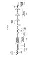
- Figure 5 illustrates the entire steps carried out in a hot rolling line.
- a steel slab 90 is rough rolled by hot roughing mills 50, to become a sheet bar 95.
- the sheet bar 95 is finish rolled by hot finishing stands 60 into an elongate steel strip 100.
- the sheet bars 50 are finish rolled one by one, and the resultant steel strips are coiled by coilers 30 one by one (each strip being coiled on one of coiler drums). After one steel strip is taken up on one coiler drum, in the conventional batch rolling system, there is sufficient time for such a preparatory operation as to enable the next steel strip to be coiled on another coiler drum.
- a welder 70 for joining the sheet bars 95 is provided between the roughing mills 50 and the finishing stands 60, so as to joint the leading end of the succeeding sheet bar to the tail end of the preceding sheet bar. Therefore, the hot finishing stands 60 performs continual rolling of a multiplicity of sheet bars 95 joined together. Since the joined body of sheet bars 95 finish rolled continually in this manner has discontinuity only at the foremost and backmost ends, it is possible to carry out high-speed finish rolling, without any complicated modification of rolling speed.
- FIG. 4 shows an apparatus according to the prior art, in which pinch rolls 40, 42 can be moved farther apart, and a deflector 44 capable of being moved up and down is provided on the entry side of coiler drums 30a, 30b so as to change the traveling direction of the steel strip 100.
- the deflector 44 is provided with auxiliary rollers 48 small in diameter. In this conventional apparatus, a slight deviation in the position of contact of the strip 100 with the roller 48 can render the strip guiding direction unstable, making it impossible to coil the strip.
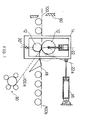
- Figure 1 is an illustration of the apparatus for coiler drum alternation according to this invention.
- rough-rolled sheet bars are jointed end to end at a position on the entry side of the finishing stands, the jointed sheet bars are continually hot rolled in the finishing stands, the resultant steel strip is cut up on the entry side of coilers, and the cut lengths of strip are successively coiled, in an alternating manner, on a plurality of coilers arranged in series.
- upper and lower pinch rolls 10 and 12 are placed in a housing 14.
- the housing 14 is so designed as to be tilted by a hydraulic cylinder 16.
- the housing 14 is tilted by the hydraulic cylinder 16 so that the center line 22 passing through the centers of the upper and lower pinch rolls 10, 12 is tilted as indicated by 22a, and a deflector 18 is directed to the side of the coiler 30, whereby the strip 100 is coiled.
- the housing 14 is returned into the solid-line position in Figure 1, and the deflector 18 into the position for directing downstream.
- Figure 2 shows the changeover from a coiler 30b on the downstream side to a coiler 30a on the upstream side.
- a housing 14 on the upstream side is tilted so that the center line passing through the centers of the upper and lower pinch rolls 10a, 12a is tilted, the upstream-side coiler 30a is set ready for coiling, and the steel strip 100 is cut by the shear 80.
- the upper and lower pinch rolls 10b, 12b of the downstream-side coiler 30b may be in the non- tilted condition. It is thereby possible to maintain a tail end portion of the steel strip 100b securely by the pinch rolls 10b, 12b until the coiling of the strip 100b is finished, and to obtain a better coil form.
- Figure 3 shows a changeover from the coiler 30a on the upstream side to the coiler 30b on the downstream side.
- the housing 14b on the downstream side is tilted so that the center line passing through the centers of the upper and lower pinch rolls 10b, 12b of the downstream-side coiler 14b is tilted, and the downstream-side coiler 30b is set ready for coiling.
- the center line passing through the centers of the upper and lower pinch rolls 10a, 12a of the upstream-side coiler 30a is kept untilted.
- the steel strip 100 is cut by the shear while the upper pinch roll 10a of the upstream-side coiler 30a is thus prevented from exerting a downward bending force on the succeeding portion of strip.
- the succeeding portion of strip is moved straight ahead to be caught by the pinch rolls 10b, 12b on the downstream side, and is wrapped around the downstream-side coiler 30b.
Abstract
Description
- This invention relates to a process for coiler drum alternation in incessant hot rolling of steel strip and to an apparatus therefor.
- By the term "incessant hot rolling" herein is meant a system in which preceding ones and succeeding ones of rough rolled slabs are joined together one after another by a flying welder on the entry side of a finishing hot rolling mill, and the joined slabs are subjected continually to finish hot rolling to produce a steel strip.
- In hot rolling lines, conventionally, rolling of steel strips has been carried out by the batch rolling system. That is to say, it has been a common practice to rough roll the rolling stocks one by one to make sheet bars, finish roll the sheet bars to steel strips, and take up the steel strips by coilers, respectively. In order to moderate the impact load at an actual nip of the rolls for gripping the rough rolled sheet bar into the finish rolling mill, in the batch rolling system, it has been necessary to limit the traveling speed of the sheet bar at the actual nip. In addition, it has also been necessary to vary the rolling speed, for controlling the plate thickness and shape of the head and tail ends of the rolled product. In the finish rolling of thin sheets, in particular, the traveling speed of the steel strip has been controlled to or below a predetermined value until the leading end of the strip starts being wrapped around the mandrel of the coiler, so as to prevent the leading end portion from being lifted while traveling. Thus, the batch rolling system has the drawback of varied rolling speeds and low rolling efficiency. In addition, the batch rolling system involves waste of time in, for example, pepara- tory operations between the rolling of a preceding rolling stock and the rolling of the following rolling stock, leading to low efficiency in using the equipment. Furthermore, there has been the problem that the finish rolled products are liable to have poor shape at the head and tail ends thereof, resulting in a low production efficiency, and so on.
- For solving these problems, incessant hot rolling is adopted. In the incessant hot rolling, the steel strip obtained by continual rolling of joined slabs is cut up by a flying shear into lengths of strip corresponding to the initial slabs, followed by coiling by coilers. It is necessary in this case to change over the path of the steel strip so that the leading ends of the cut lengths of strip are guided to be taken up on the respective coiler drums. Techniques for such coiler drum ternation are disclosed in Japanese Patent Application Laid-Open (KOKAI) No. 61-014003 (1986) (Process for Down-Coiler Alternation in Incessant Hot Rolling) and Japanese Patent Application Laid-Open (KOKAI) No. 61-119326 (1986) (Gate Device for RollingLine Alternation).
- According to the Japanese Patent Application Laid-Open (KOKAI) No. 61-119326 (1986), a deflector disposed on the entry side of coiler rolls is moved up and down to achieve alternation of coilers. The up-down motion of the deflector may flaw the steel strip. To avoid the formation of flaws, the deflector is provided with auxiliary rollers. Since the auxiliary rollers are to be arranged in a limited space, however, the rollers should be small in diameter and, due to the small roller diameter, a slight deviation in the position of contact of the roller with the steel strip can render the strip guiding direction unstable, making it impossible to coil the strip. In the technique according to the Japanese Patent Application Laid-Open (KOKAI) No. 61-014003 (1986), on the other hand, each coiler is provided with a main and an auxiliary set of pinch rolls, which are operated to achieve coiler drum alternation. This technique requires a complicated mechanism.
- It is accordingly an object of this invention to enable higher-speed alternation of coiler drums for coiling of cut steel strips in incessant hot rolling, one by one, and to achieve higher productivity.
- It is another object of this invention to enable an easy and assured change of direction so as to guide the leading end of a cut steel strip toward the next coiler to be used.
- It is a further object of this invention to enable changeover from a coiler on the downstream side to a coiler on the upstream side.
- In order to attain the above objects, this invention makes an improvement on the alternation of coiler drums for a traveling steel strip in incessant hot rolling, by adopting the following process. The process for coiler drum alternation in incessant hot rolling comprises the steps of oscillating upper and lower tillable pinch rolls disposed on the exit side of a shear, thereby changing the direction of the steel strip so that a leading end formed upon cutting the strip will be directed toward the coiler drum to be used next, and cutting the steel strip.
-
- Figure 1 is an illustration of an alternation apparatus preferable for carrying out this invention;
- Figure 2 is an illustration of an alternation process according to this invention, in the case of changeover from a coiler on the downstream side to a coiler on the upstream side;
- Figure 3 is an illustration of changeover from a coiler on the upstream side to a coiler on the downstream side;
- Figure 4 is an illustration of an exemplary system according to the prior art; and
- Figure 5 is a general view of a hot rolling line.
- Figure 5 illustrates the entire steps carried out in a hot rolling line. A steel slab 90 is rough rolled by
hot roughing mills 50, to become asheet bar 95. Thesheet bar 95 is finish rolled by hot finishing stands 60 into anelongate steel strip 100. In the conventional batch rolling system, thesheet bars 50 are finish rolled one by one, and the resultant steel strips are coiled bycoilers 30 one by one (each strip being coiled on one of coiler drums). After one steel strip is taken up on one coiler drum, in the conventional batch rolling system, there is sufficient time for such a preparatory operation as to enable the next steel strip to be coiled on another coiler drum. - In the incessant hot rolling to which this invention is applied, a
welder 70 for joining thesheet bars 95 is provided between theroughing mills 50 and the finishing stands 60, so as to joint the leading end of the succeeding sheet bar to the tail end of the preceding sheet bar. Therefore, thehot finishing stands 60 performs continual rolling of a multiplicity ofsheet bars 95 joined together. Since the joined body ofsheet bars 95 finish rolled continually in this manner has discontinuity only at the foremost and backmost ends, it is possible to carry out high-speed finish rolling, without any complicated modification of rolling speed. - After the continual finish rolling, the
steel strip 100 is cut at the joint portions thereof by ashear 80, and the cut lengths of strip are coiled separately by thecoilers 30. For the cutting of thesteel strip 100 during the highspeed rolling and for alternation of thecoilers 30 in preparation for the next coiling operation, the path for the steel strip should be changed assuredly at high speed. Figure 4 shows an apparatus according to the prior art, in which pinch rolls 40, 42 can be moved farther apart, and adeflector 44 capable of being moved up and down is provided on the entry side ofcoiler drums steel strip 100. Thedeflector 44 is provided withauxiliary rollers 48 small in diameter. In this conventional apparatus, a slight deviation in the position of contact of thestrip 100 with theroller 48 can render the strip guiding direction unstable, making it impossible to coil the strip. - Figure 1 is an illustration of the apparatus for coiler drum alternation according to this invention. In the process for coiler drum alternation in incessant hot rolling according to this invention, rough-rolled sheet bars are jointed end to end at a position on the entry side of the finishing stands, the jointed sheet bars are continually hot rolled in the finishing stands, the resultant steel strip is cut up on the entry side of coilers, and the cut lengths of strip are successively coiled, in an alternating manner, on a plurality of coilers arranged in series.
- In Figure 1, upper and
lower pinch rolls housing 14. Thehousing 14 is so designed as to be tilted by ahydraulic cylinder 16. To coil asteel strip 100 by acoiler 30, therefore, thehousing 14 is tilted by thehydraulic cylinder 16 so that thecenter line 22 passing through the centers of the upper andlower pinch rolls deflector 18 is directed to the side of thecoiler 30, whereby thestrip 100 is coiled. At the time of coiling by a coiler on the downstream side, thehousing 14 is returned into the solid-line position in Figure 1, and thedeflector 18 into the position for directing downstream. - The process for coiler drum alternation is illustrated in Figures 2 and 3. Figure 2 shows the changeover from a
coiler 30b on the downstream side to acoiler 30a on the upstream side. To make a changeover from the coiling of thesteel strip 100 by the downstream-side coiler 30b to that by the upstream-side coiler 30a, ahousing 14 on the upstream side is tilted so that the center line passing through the centers of the upper andlower pinch rolls side coiler 30a is set ready for coiling, and thesteel strip 100 is cut by theshear 80. In this case, the upper andlower pinch rolls side coiler 30b may be in the non- tilted condition. It is thereby possible to maintain a tail end portion of thesteel strip 100b securely by thepinch rolls strip 100b is finished, and to obtain a better coil form. - Figure 3 shows a changeover from the
coiler 30a on the upstream side to thecoiler 30b on the downstream side. - To make a changeover from the coiling of a
steel strip 100a by the upstream-side coiler 30a to the coiling of asteel strip 100b by the downstream-side coiler 30b, thehousing 14b on the downstream side is tilted so that the center line passing through the centers of the upper andlower pinch rolls side coiler 14b is tilted, and the downstream-side coiler 30b is set ready for coiling. In this case, the center line passing through the centers of the upper andlower pinch rolls side coiler 30a is kept untilted. Thesteel strip 100 is cut by the shear while theupper pinch roll 10a of the upstream-side coiler 30a is thus prevented from exerting a downward bending force on the succeeding portion of strip. Upon the cutting of thesteel strip 100, the succeeding portion of strip is moved straight ahead to be caught by thepinch rolls side coiler 30b. - This invention produces the following excellent effects:
- (1) The need for a deflector with a complicated construction, as in the prior art, is eliminated.
- (2) The tail end of the preceding steel strip can be clamped by the upper pinch roll.
- (3) The head end of the succeeding steel strip can be guided by the upper pinch roll.
- (4) It is sufficient to provide the coiler on the upstream side with only one set of pinch rolls, as contrasted to two sets of pinch rolls required according to the prior art.
Claims (4)
Applications Claiming Priority (2)
| Application Number | Priority Date | Filing Date | Title |
|---|---|---|---|
| JP201309/90 | 1990-07-31 | ||
| JP2201309A JPH0489135A (en) | 1990-07-31 | 1990-07-31 | Method for changing over coiler of endless hot rolling |
Publications (2)
| Publication Number | Publication Date |
|---|---|
| EP0469483A2 true EP0469483A2 (en) | 1992-02-05 |
| EP0469483A3 EP0469483A3 (en) | 1992-04-08 |
Family
ID=16438871
Family Applications (1)
| Application Number | Title | Priority Date | Filing Date |
|---|---|---|---|
| EP19910112604 Withdrawn EP0469483A3 (en) | 1990-07-31 | 1991-07-26 | Process for coiler drum alternation in incessant hot rolling and apparatus therefor |
Country Status (5)
| Country | Link |
|---|---|
| EP (1) | EP0469483A3 (en) |
| JP (1) | JPH0489135A (en) |
| KR (1) | KR950001807B1 (en) |
| CN (1) | CN1034400C (en) |
| CA (1) | CA2048127C (en) |
Cited By (4)
| Publication number | Priority date | Publication date | Assignee | Title |
|---|---|---|---|---|
| EP0790084A3 (en) * | 1996-02-14 | 1998-04-29 | Sms Schloemann-Siemag Aktiengesellschaft | Winding device for bands |
| KR100453435B1 (en) * | 1996-02-14 | 2006-01-27 | 에스엠에스 데마그 악티엔게젤샤프트 | Winding device for bands |
| DE102008016314A1 (en) | 2007-03-28 | 2008-10-02 | Sms Demag Ag | Method and device for winding hot strip |
| CN111032241A (en) * | 2017-08-18 | 2020-04-17 | Posco公司 | Winding device |
Families Citing this family (10)
| Publication number | Priority date | Publication date | Assignee | Title |
|---|---|---|---|---|
| US5769219A (en) * | 1995-06-08 | 1998-06-23 | Shimel; Jerry W. | Beverage storage apparatus for use with a golf bag |
| DE10208964A1 (en) * | 2002-02-28 | 2003-09-18 | Sms Demag Ag | Deflection device for a belt in a reel system |
| DE10258499A1 (en) * | 2002-12-14 | 2004-07-01 | Sms Demag Ag | Deflection device of a reel system for reeling tapes |
| DE102006029858A1 (en) * | 2006-06-28 | 2008-01-03 | Sms Demag Ag | Method and device for winding a metallic strip |
| CN102513409A (en) * | 2011-12-24 | 2012-06-27 | 中国重型机械研究院有限公司 | Rapid strip valve system of tandem cold mill set |
| CN105059998A (en) * | 2015-08-12 | 2015-11-18 | 安徽江威精密制造有限公司 | Angle conversion device |
| CN107282693A (en) * | 2017-06-29 | 2017-10-24 | 广东含元工业技术有限公司 | A kind of hydraulic drum structure of sheet metal strip |
| CN112893515B (en) * | 2021-03-03 | 2022-08-09 | 烟台孚信达双金属股份有限公司 | Laminated winding machine for bar mosquito-repellent incense discs |
| CN114589214A (en) * | 2022-02-28 | 2022-06-07 | 首钢京唐钢铁联合有限责任公司 | Lower pinch roll winding treatment method and device |
| CN115106398B (en) * | 2022-07-28 | 2023-10-27 | 射洪县才伦建材有限责任公司 | Split-type spiral coil winding processing equipment for steel bar production |
Citations (4)
| Publication number | Priority date | Publication date | Assignee | Title |
|---|---|---|---|---|
| AT218993B (en) * | 1959-11-27 | 1962-01-10 | Siemens Ag | Digital path-dependent control device |
| JPS6114003A (en) * | 1984-06-29 | 1986-01-22 | Sumitomo Metal Ind Ltd | Changing method of down coiler for continuous hot rolling |
| GB2163689A (en) * | 1984-08-31 | 1986-03-05 | Davy Mckee | Hot rolling metal strip |
| JPS61119326A (en) * | 1984-11-16 | 1986-06-06 | Mitsubishi Heavy Ind Ltd | Rolling line changeover gate device |
Family Cites Families (8)
| Publication number | Priority date | Publication date | Assignee | Title |
|---|---|---|---|---|
| JPH01250246A (en) * | 1987-09-21 | 1989-10-05 | Nippon Petrochem Co Ltd | Medical tray |
| JP2003265584A (en) * | 2002-03-15 | 2003-09-24 | Yamato Sanki:Kk | Circulation system of sterilization work of medical equipment material between medical facility and undertaker |
| JP3947686B2 (en) * | 2002-06-11 | 2007-07-25 | オリンパス株式会社 | Medical device reuse management system and computer-based medical device reuse management method |
| JP4338464B2 (en) * | 2003-07-11 | 2009-10-07 | Hoya株式会社 | Endoscope cleaning tool |
| US7918896B2 (en) * | 2004-09-15 | 2011-04-05 | Wright Medical Technology, Inc. | Unitary acetabular cup prosthesis with extension for deficient acetabulum |
| EP2073761B1 (en) * | 2006-09-21 | 2010-07-07 | SpineCore, Inc. | Intervertebral disc implants and tooling |
| US8740912B2 (en) * | 2008-02-27 | 2014-06-03 | Ilion Medical Llc | Tools for performing less invasive orthopedic joint procedures |
| AU2008363197B2 (en) * | 2008-10-21 | 2015-06-25 | Steris Solutions Limited | Medical equipment storage and transportation kit |
-
1990
- 1990-07-31 JP JP2201309A patent/JPH0489135A/en active Pending
-
1991
- 1991-07-26 EP EP19910112604 patent/EP0469483A3/en not_active Withdrawn
- 1991-07-30 CA CA002048127A patent/CA2048127C/en not_active Expired - Fee Related
- 1991-07-31 CN CN91105632A patent/CN1034400C/en not_active Expired - Fee Related
- 1991-07-31 KR KR1019910013156A patent/KR950001807B1/en not_active IP Right Cessation
Patent Citations (4)
| Publication number | Priority date | Publication date | Assignee | Title |
|---|---|---|---|---|
| AT218993B (en) * | 1959-11-27 | 1962-01-10 | Siemens Ag | Digital path-dependent control device |
| JPS6114003A (en) * | 1984-06-29 | 1986-01-22 | Sumitomo Metal Ind Ltd | Changing method of down coiler for continuous hot rolling |
| GB2163689A (en) * | 1984-08-31 | 1986-03-05 | Davy Mckee | Hot rolling metal strip |
| JPS61119326A (en) * | 1984-11-16 | 1986-06-06 | Mitsubishi Heavy Ind Ltd | Rolling line changeover gate device |
Non-Patent Citations (2)
| Title |
|---|
| PATENT ABSTRACTS OF JAPAN vol. 10, no. 159, 7 June 1986; & JP - A - 61014003 (SUMITOMO KINZOKU KOGYO KK) 22.01.1986 * |
| PATENT ABSTRACTS OF JAPAN vol. 10, no. 307, 18 October 1986; & JP - A - 61119326 (MITSUBISHI) 06.06.1986 * |
Cited By (8)
| Publication number | Priority date | Publication date | Assignee | Title |
|---|---|---|---|---|
| EP0790084A3 (en) * | 1996-02-14 | 1998-04-29 | Sms Schloemann-Siemag Aktiengesellschaft | Winding device for bands |
| US5966978A (en) * | 1996-02-14 | 1999-10-19 | Sms Schloemann-Siemag Aktiengesellschaft | Reeling unit for strip |
| CN1081495C (en) * | 1996-02-14 | 2002-03-27 | Sms舒路曼-斯玛公司 | Device for winding up steel band |
| KR100453435B1 (en) * | 1996-02-14 | 2006-01-27 | 에스엠에스 데마그 악티엔게젤샤프트 | Winding device for bands |
| DE102008016314A1 (en) | 2007-03-28 | 2008-10-02 | Sms Demag Ag | Method and device for winding hot strip |
| US9238259B2 (en) | 2007-03-28 | 2016-01-19 | Sms Group Gmbh | Method and device for winding hot-rolled strip |
| CN111032241A (en) * | 2017-08-18 | 2020-04-17 | Posco公司 | Winding device |
| EP3670013A4 (en) * | 2017-08-18 | 2020-08-26 | Posco | Coiling device |
Also Published As
| Publication number | Publication date |
|---|---|
| CN1034400C (en) | 1997-04-02 |
| CA2048127C (en) | 1997-01-21 |
| CA2048127A1 (en) | 1992-02-01 |
| JPH0489135A (en) | 1992-03-23 |
| KR920002243A (en) | 1992-02-28 |
| KR950001807B1 (en) | 1995-03-03 |
| EP0469483A3 (en) | 1992-04-08 |
| CN1060798A (en) | 1992-05-06 |
Similar Documents
| Publication | Publication Date | Title |
|---|---|---|
| RU2216416C2 (en) | Method and plant for hot rolling of flat billets | |
| EP0469483A2 (en) | Process for coiler drum alternation in incessant hot rolling and apparatus therefor | |
| EP0968774B1 (en) | A method for manufacturing a hot-rolled steel strip | |
| JPS61259804A (en) | Method and device for rolling band material before finishingto hot wide band material | |
| US4123011A (en) | Coil unwind and wind-up method and apparatus therefor | |
| US3834207A (en) | Method and apparatus for forming an accurately dimensioned metal strip having varying thickness | |
| US3700157A (en) | Apparatus for feeding strip-like material to a processing apparatus | |
| EP1289687B1 (en) | Method and installation for producing a metal strip | |
| JPH04105701A (en) | Method and equipment for continuous hot rolling of thin sheet | |
| CA2229255C (en) | Long slab rolling process and apparatus | |
| JP2002219501A (en) | Manufacturing method of hot steel strip and its manufacturing facilities | |
| EP3208005B1 (en) | Combined welding and rolling plant for metallic strips | |
| JP4022103B2 (en) | Method for controlling the speed of the outgoing strip of a hot finish rolling mill in a hot rolling line. | |
| JP2820520B2 (en) | Switching method of winder in endless hot rolling | |
| US5767475A (en) | Hot rolling method | |
| JP2003025015A (en) | Method for coiling steel strip | |
| JPH1099916A (en) | Coiling equipment for continuous hot rolling and coiling method with the same | |
| JPH04228217A (en) | Device for switching transporting direction of hot rolled steel strip and device for coiling | |
| JP3292608B2 (en) | Rolling cutting method of endless hot rolled steel strip | |
| JPH09150201A (en) | Continuous sheet processing facility | |
| US5804790A (en) | Hot rolling method | |
| JPH06170411A (en) | Continuous hot rolling equipment for billet | |
| JP2000254704A (en) | Method and device for producing hot-rolled steel sheet with plate thickness press | |
| SU1479150A1 (en) | Method of hot rolling strips and sheets | |
| JPH1094801A (en) | Method for pressing width of hot slab |
Legal Events
| Date | Code | Title | Description |
|---|---|---|---|
| PUAI | Public reference made under article 153(3) epc to a published international application that has entered the european phase |
Free format text: ORIGINAL CODE: 0009012 |
|
| AK | Designated contracting states |
Kind code of ref document: A2 Designated state(s): DE FR GB IT |
|
| PUAL | Search report despatched |
Free format text: ORIGINAL CODE: 0009013 |
|
| AK | Designated contracting states |
Kind code of ref document: A3 Designated state(s): DE FR GB IT |
|
| 17P | Request for examination filed |
Effective date: 19920717 |
|
| 17Q | First examination report despatched |
Effective date: 19930909 |
|
| STAA | Information on the status of an ep patent application or granted ep patent |
Free format text: STATUS: THE APPLICATION IS DEEMED TO BE WITHDRAWN |
|
| 18D | Application deemed to be withdrawn |
Effective date: 19940913 |