EP0463992A1 - Rasoir mécanique - Google Patents
Rasoir mécanique Download PDFInfo
- Publication number
- EP0463992A1 EP0463992A1 EP91810461A EP91810461A EP0463992A1 EP 0463992 A1 EP0463992 A1 EP 0463992A1 EP 91810461 A EP91810461 A EP 91810461A EP 91810461 A EP91810461 A EP 91810461A EP 0463992 A1 EP0463992 A1 EP 0463992A1
- Authority
- EP
- European Patent Office
- Prior art keywords
- application
- contour
- roller
- applicator
- preparation
- Prior art date
- Legal status (The legal status is an assumption and is not a legal conclusion. Google has not performed a legal analysis and makes no representation as to the accuracy of the status listed.)
- Granted
Links
Images


Classifications
-
- B—PERFORMING OPERATIONS; TRANSPORTING
- B26—HAND CUTTING TOOLS; CUTTING; SEVERING
- B26B—HAND-HELD CUTTING TOOLS NOT OTHERWISE PROVIDED FOR
- B26B21/00—Razors of the open or knife type; Safety razors or other shaving implements of the planing type; Hair-trimming devices involving a razor-blade; Equipment therefor
- B26B21/40—Details or accessories
- B26B21/44—Means integral with, or attached to, the razor for storing shaving-cream, styptic, or the like
- B26B21/446—Shaving aid stored in the razor handle
-
- B—PERFORMING OPERATIONS; TRANSPORTING
- B05—SPRAYING OR ATOMISING IN GENERAL; APPLYING FLUENT MATERIALS TO SURFACES, IN GENERAL
- B05B—SPRAYING APPARATUS; ATOMISING APPARATUS; NOZZLES
- B05B11/00—Single-unit hand-held apparatus in which flow of contents is produced by the muscular force of the operator at the moment of use
- B05B11/0005—Components or details
-
- B—PERFORMING OPERATIONS; TRANSPORTING
- B05—SPRAYING OR ATOMISING IN GENERAL; APPLYING FLUENT MATERIALS TO SURFACES, IN GENERAL
- B05B—SPRAYING APPARATUS; ATOMISING APPARATUS; NOZZLES
- B05B11/00—Single-unit hand-held apparatus in which flow of contents is produced by the muscular force of the operator at the moment of use
- B05B11/01—Single-unit hand-held apparatus in which flow of contents is produced by the muscular force of the operator at the moment of use characterised by the means producing the flow
- B05B11/10—Pump arrangements for transferring the contents from the container to a pump chamber by a sucking effect and forcing the contents out through the dispensing nozzle
- B05B11/1028—Pumps having a pumping chamber with a deformable wall
- B05B11/1032—Pumps having a pumping chamber with a deformable wall actuated without substantial movement of the nozzle in the direction of the pressure stroke
Definitions
- the invention is in the field of body care and relates to a shaving device for wet shaving (blade shaving) according to the preamble of the independent claims, with which hair on any part of the body (surface, rounding or contour shaving) using any preparation (for example problem shaving), that is applied by the device while shaving, can be cut off very close.
- a lubricant and softener any problem shave
- the areal application of thin layers of such cosmetic (possibly pharmaceutical) preparations to the skin is usually carried out by hand or by spraying.
- a good dosage and a very regular distribution is difficult. It is unavoidable that part of the sometimes expensive preparation to be applied remains on the application hand.
- spray cans with which the application problem is also not solved are no longer desirable because of environmental pollution.
- the hygiene problem always remains current.
- the object of the invention to provide such a device with the aid of which a pumpable preparation can be applied as a thin, regular layer over a wide area and in a manner suitable for cutting.
- the supply of preparation for application should only be possible during the application or pumping process. If there is no application, all feed paths should be automatically interrupted and shielded. For hygienic reasons, it should be prevented that contaminants are brought into the preparation from outside. It should be easy for the user to precisely dose the preparation.
- the device is said to be suitable for shaving for women as well as for men. For women-specific shaving, areas with greater curvatures, i.e.
- the device according to the characterizing parts of the independent claims consists of an applicator part, a fluid supply part and a blade part.
- the following description and the associated figures first deal generally with the interaction of the applicator part and the blade part ( Figure 1), then in detail with the applicator part ( Figures 2 and 3), with the feed part ( Figures 4 to 8) and finally with the integration of the blade part to a razor according to the invention ( Figures 9 to 19), in which the three parts come together to work.
- the blade part and applicator part are matched in terms of shape; the feed part including the reservoir is functionally matched to the applicator part, so that the applicator part on the one hand doses to the blade part and the shield to the dining area.
- this intermediate link can be designed in many ways, can be adapted to any blade shape and controls the pumped-in flow of the fluid from its reservoir.
- the application opening is preferably slit-shaped.
- the elements delimiting the opening can be movable or rigid. If they are movable, the mobility can be used for application (for example, rollers) or for shrinking to cover up the opening (for example, pivot axis of a roller, hinged or elastic lip) or for both.
- the elements delimiting the opening can be arranged in relation to the blade part (one or more cutting edges) in such a way that the cutting is mechanically supported, so that the geometry of the cutting edge (s) and opening limiting element (s) is of additional importance.
- the application opening is in turn connected via the feed part to the fluid reservoir, which is shielded by the feed channel and the delimiting elements, in order to meet the hygiene requirements.
- 1.1 shows an abstracted schematic representation of the feeding, application and cutting function of a shaving device according to the invention.
- ⁇ is an application angle
- ⁇ is a cutting angle
- the two angles relate to the skin surface H.
- an applicator part (manipulation part) 30.2 which influences the cutting angle and which on the one hand delimits the application opening on the blade side and optionally the Fluid channel 10 is the closing part.
- a crossed double arrow shows the adjustment options. Pushed towards the skin surface, it causes a local pushing back of the skin surface H into the position H '.
- the scraping A which is hair and abrasion from the preparation and skin, can be removed between the blade 2 and the manipulation part 30.2.
- the fluid In the fluid channel, the fluid is conveyed to the applicator part under a certain pump pressure (arrow p) and emerges at the application opening in the area of the skin surface. If the blade part is moved in the cutting direction, the applicator part distributes the preparation over the skin surface.
- FIG. 1.2 also schematically shows an embodiment in which the fluid channel 10 of the applicator part is formed with spatula-shaped wall parts 30, 30.2.
- the applicator part 30.2 (manipulation part) influencing the cutting angle, which on the one hand delimits the application opening on the blade side and optionally by swiveling back the part closing the fluid channel 10 is indicated by a double arrow in its adjustment possibility.
- the skin surface is influenced more or less, which is indicated by a local pushing back of the skin surface H into the position H '.
- the outlet opening formed by the two wall parts 30.1 and 30.2 also changes, through which the fluid exits in the direction of the skin.
- spatula-shaped manipulator part 30.2 If the spatula-shaped manipulator part 30.2 is brought into a rest position in which the outlet opening of the fluid channel 10 is closed, for example by means of spring pressure, a movement of the blade part in the cutting direction causes the latter to open, so that the fluid under pump pressure can emerge unhindered. At the same time it is spread by the spatula part 30.2 on the skin surface.
- the fluid channel 10 of the applicator part can be closed or at least narrowed by a roller-shaped addition to the wall parts 30.1, 30.2.
- the applicator part 30.2 (manipulation part) influencing the cutting angle is, for example, a cylindrical roller 3, which on the one hand delimits the application opening on the blade side and partially covers the fluid channel by its position.
- the adjustment options are indicated by a double arrow if the roller 3 is mounted in a slot-shaped bearing.
- the channel is covered more or less.
- the skin surface is influenced more or less, that is, locally pushed back into a position H ', as shown in Figure 1.2.
- roller-shaped manipulator part 30.2 If the roller-shaped manipulator part 30.2 is brought into a rest position, in which the outlet opening of the fluid channel 10 is closed, for example by means of spring pressure, a movement of the blade part in the cutting direction causes the latter to open, so that the fluid under pump pressure can emerge unhindered. At the same time, roller part 30.2 spreads it on the skin surface.
- FIG. 1.4 shows a schematic section through an exemplary embodiment of the device according to the invention, which consists of the three parts, namely an applicator, a cutting device and a feed device from which the preparation is fed into the applicator.
- the applicator corresponds to the roller solution according to Figure 1.3.
- the cutting device is integrated in the applicator, that is to say the cutting device and applicator together form the shaving head 1.
- the main component of the applicator is an application roller 3 arranged parallel to the blades 2.
- the feeding device is accommodated in the handle 4 of the device and consists of a small pump 5 and a reservoir 6.
- the shaving head 1 is pulled over the skin with the aid of the handle 4 in such a way that the application roller 3 rolls over the skin immediately in front of the blades 2.
- the pump 5 is positioned in such a way that it lies between the thumb and forefinger and, depending on the embodiment, can be actuated by lightly alternating pressing and releasing.
- the preparation is pumped from the reservoir 6 into the applicator and distributed as a thin film on the application roller 3 and transferred from there to the skin.
- the dosage is easy. If the dosage is too short, the application roller will run dry, if the dosage is too strong, the drops will form.
- the applicator consists of an application roll and a feed system.
- the application roll is rolled over the skin for the application, for example.
- it is rotatably and pivotably mounted so that it is swung out in one direction (application direction R) when unrolling, while it remains in its rest position when unrolling in the other direction and, if it is not rolling. Swinging out makes it possible for a thin film of preparation to be carried outwards from the feed system on the roll surface.
- the application roller shields the feed system from the outside.
- the application roll is fixed and the gap width remains constant. This embodiment is suitable for preparations that do not dry out too much and tend to form little film.
- the application roller can also only be pivoted but not rotatably mounted, so that it closes and opens the application opening, but acts for the application itself in approximately the same way as an application spatula, as will be described in the following.
- FIG. 2a shows an applicator from the side. It consists of the roller 3, a head piece 21 and two bearing parts 22 attached laterally from the head piece 21.
- the bearings 23 in the bearing parts 22 are either designed such that they not only rotate the roller 3 about its axis of rotation, but also pivot it out Allow axis of rotation or so that they only move about their axis of rotation.
- the first variant results in a variable application gap width and in the second variant a fixed application gap width.
- FIG. 2b which represents a separate bearing part 22, a bearing 23, which enables a variable application gap width, is also shown separately.
- FIG. 3a shows a section through the head part 21 of the embodiment of the applicator shown in FIG. 2a.
- the bore opens into a channel 32, which runs parallel to reel 3 and is open toward reel 3.
- the head part is shaped into lips 33.1 and 33.2 on both sides of the channel 32.
- the bearings of the roller 3 in the bearing parts 22 are designed in such a way that the roller can assume two extreme pivot positions: a "rest position” (shown in solid lines in the figure) and an "application position”"(shown in dashed lines in the figure).
- a "rest position” shown in solid lines in the figure
- an "application position” shown in dashed lines in the figure.
- both the column A between the lip 33.1 and the roller 3 and the column C between the lip 33.2 and the roller 3 are so narrow that no preparation can escape and the channel 32 and thus the feed system is shielded from the outside.
- the roller 3 is moved from the rest position into the application position, the width of the column A does not change, while the column C widens until its width in the application position corresponds to the desired exit quantity for the preparation.
- the application position for a desired exit quantity can also remain fixed, so that the rest position corresponds to that of the application position.
- the shielding is then good or better, and the drying is good or worse.
- the roller 3 is pulled over the skin in the application direction, it is rotated by the friction between the skin and the roller in the direction of the arrow R and is thereby pivoted into the application position and held in it. If the roller 3 is rotated in the direction opposite the arrows R, it is pivoted into the rest position and held in this position. If the roller 3 is in its application position, but is no longer rotated in the application direction, which is the case immediately after application, it is withdrawn against the rest position by the surface tension of the preparation surface in the gap C. The physical properties of the preparation are therefore used to close gap C after application. The surface is under tension that tries to reduce the surface to a minimum.
- the roller is moved against the rest position as soon as it is not moved in the opposite direction by the application movement is pressed. If the applicator is left to itself after the gap C is closed by the surface tension, a skin forms in the gap C by drying the preparation surface, which shields the rest of the preparation from the outside in the delivery system. This shielding is sufficient to prevent further drying of the preparation and to protect the preparation against oxidants and bacteria, for example. When reapplied, the skin covering gap C is immediately torn and does not interfere with the application in any way.
- the gap A between the lip 33.1 and the roller 3 is very small in any pivoting position (open / closed or for, correspondingly open) of the roller 3, the channel 32 on the side of the lip 33.1 is always closed to the outside. In the rest position and in the application position of the roller 3, no preparation can get out in this direction, in the application position no contamination that carries the roller from the skin past the lip 33.1 can pass into the channel 32. In the embodiment with a fixed gap, this is only weakened.
- the applicator can also have a lid which is placed on the applicator after the application has ended and which is shaped such that it presses the roller 3 against the two lips 33.1 and 33.2 or simply covers the application gap.
- additional mechanical pressing means for example springs, can be provided in order to press the application roller 3 against the sealing lip. This may be necessary if, for example, such a shaving device is exposed to strong pressure fluctuations in travel versions and an additional closing force is desired on the device.
- FIG. 3b shows a section through the embodiment of the applicator according to the invention with a variable gap. It shows the same parts as the applicator shown in FIG. 3a, but a blade carrier 34 with blades 2 is placed on its head part 21 by means of, for example, a sliding and snap fastening.
- the roller 3 is advantageously as long as the width of the blade or blades 2.
- the blade carrier 34 is placed on the head part 21 in such a way that the roller runs parallel to the blades and when the shaving head is guided over the skin in the shaving direction (same as the application direction) is rotated in the direction of arrow R and is thereby pivoted into the application position.
- the application device with application roller 3, head part 21 and bearing parts 22 can also be integrated in an exchangeable blade carrier, which can be placed or exchanged as a whole on a shaving head.
- This solution has hygienic advantages because the application roller that comes into contact with the skin is periodically renewed with the blades.
- the supply part arranged on the blade carrier is connected to the supply part arranged on the razor by suitable measures.
- FIG. 4a shows a schematic longitudinal section through an exemplary embodiment of the feeding device according to the invention.
- this consists of a small pump 5 and a reservoir 6, both of which together, for example, simultaneously form the handle 4 of the application device, or are accommodated in a corresponding handle.
- the reservoir 6, as shown, is accommodated in the end 4.1 of the handle (reservoir part of the handle) facing away from the applicator, where a sufficient volume does not have a disruptive effect.
- the small pump 5 is advantageously arranged in such a way that it can be actuated during application, that is to say its actuating members are located in the region of the fingers holding the handle during application, that is to say at the end of the handle facing the applicator, and forms the pump part 4.2 of the handle .
- the handle 4 is connected to the connection part 4.3 with the supply system of the applicator.
- the main components of the small pump are an elastic bellows 41, the internal volume of which can be reduced, a one-way valve 42, which functions as an outlet valve for the reservoir 6, and a second one-way valve 43, which functions as an inlet valve in the applicator.
- the reservoir is provided with an appropriate pressure equalization means so that pressure equalization is possible when the preparation is pressed out of the reservoir.
- This can be, for example, a piston 48 movable in the reservoir 6 or a pressure compensation valve.
- an inner pump body 44 is mounted inside the bellows 41, which in this exemplary embodiment has the shape of a tube, fixed to the reservoir part 4.1 of the handle and is connected to the connecting part 4.3 and is provided with openings 45 for pressure equalization. Because the inner pump body is angled, it forms an ergonomic handle together with the other parts of the feed device.
- the bellows 41 is placed over the inner pump body 44 and clamped in place with elastically deformable means 46, for example clamping rings.
- the two one-way valves 42 and 43 are, for example, diaphragm valves.
- a resilient membrane 47.1 keeps the outlet of the reservoir closed in the force-free state and a corresponding membrane 47.2 keeps the entrance to the applicator closed.
- the two membranes are arranged in such a way that the membrane 47.2 is deformed in the event of overpressure within the bellows, but the membrane 47.1 in the case of underpressure.
- the membranes are designed in such a way that they allow the preparation to pass through when deformed.
- Figures 4b to d show examples of membranes suitable for use. 4b and c represent hollow spherical membranes which comprise openings D lying outside the area of the opening to be closed, FIG. 4d a rectangular membrane which, by not spanning the entire inner cross section of the handle, allows passage for the preparation.
- Figure 5 shows a further embodiment of the small pump.
- the pump itself is designed in the same way as the pump in FIG. 4, but includes other one-way valves 42 and 43. As shown in FIG. 5a, these one-way valves can be ball or piston valves.
- a ball 51 or a piston 52 are pressed by a spring 53 in a direction opposite to the pressure force generated by the bellows 41 against the opening to be closed.
- the spring 53 is designed so that the pressure force that can be generated with the bellows 41 is greater than the spring force.
- the piston 52 must allow passage for the preparation. For this purpose it can be provided, for example, on its cylindrical surface with grooves 55, which can be seen in the detailed drawing 5b.
- the inner pump body 44 which is advantageously made of metal, is a separate part, while the reservoir part 4.1 of the handle and the connection part 4.3 to the applicator with elastically deformable clamp connections on the K ends are provided.
- the bellows 41 is put over the pump body 44 and then the reservoir part 4.1 of the handle and the connecting part 4.3 are put on.
- the bellows 41 also performs its function as a pump part and also functions as a sealant between the different parts of the feed device.
- FIG. 5c represents the same embodiment variant as FIG. 5a, but is provided with diaphragm valves.
- design variants are like shown in Figure 4, but provided with ball or piston valves, conceivable.
- FIGS. 6 to 8 show further embodiments for the small pump and its connections to the reservoir part 4.1 of the handle and the connection part 4.3 to the applicator.
- the variant shown in FIG. 6 contains an inner pump body which has the shape of a block with corresponding bores which contain the one-way valves 42 and 43.
- the pump body 61 is provided with grooves 62.1 / 2 and with stops 63.1 / 2 such that the correspondingly shaped bellows 41 can be slipped over it during assembly and the thickened bellows ends 64.1 / 2 come to rest in the grooves 62.1 / 2 while the parts 4.1 and 4.3, which in turn are provided with elastically deformable connection points K, are pushed over the stops 63.1 / 2.
- FIG. 7 shows a further embodiment variant of the small pump and its connections to reservoir part 4.1 and connection part 4.3.
- reservoir part 4.1 and connecting part 4.3 have elastically deformable connection points K, in that, as shown in FIG. 7b, they are equipped with a longitudinal slot L.
- the pump body 44 is plug-shaped at its two ends in such a way that the reservoir part 4.1 and the connecting part 4.3 can be simply plugged on.
- the sealing function is also carried out here by the correspondingly shaped bellows ends of the bellows 41 placed over the pump body 44.
- FIG. 8 shows an embodiment of the small pump which is advantageous due to its simplicity.
- Reservoir part 4. 1 pump body 44 and connecting part 4.3 of the Handle 4 are held together by the tubular bellows 41, for example glued or welded.
- the membranes 47.1 and 47.2 are between reservoir part 4.1 and pump body 44. mounted between connector 4.3 and pump body 44.
- the elastic, tubular bellows 41 connects the individual parts of the handle, seals all connection points and serves as a pump operating element.
- FIG. 9 shows, as an exemplary embodiment, a complete shaving device consisting of a feeding device, applicator and cutting device, which is placed on the applicator in the form of a blade holder with blades.
- a small pump 5 and reservoir 6 form the handle.
- the headpiece 21 of the applicator is connected directly to the small pump 5, and is designed in such a way that a blade carrier 34 can be attached to it.
- the applicator corresponds to the embodiment described in connection with FIG. 3b.
- the small pump 5 consists of a cylindrical pump body 44, the diameter of which is larger at both ends than in its central part, and a tubular bellows 41 which is placed over the central part of the pump body 44.
- the reservoir 6 is firmly connected to the pump body 44.
- the applicator comprises a connection part which overlaps the pump body and is fastened to the pump body, for example, with the aid of fastening screws 92.
- the two one-way valves 42 and 43 are integrated in the pump body 44.
- the outlet valve 42 from the reservoir consists of an axial bore 93 which extends from the end face of the reservoir to the part with a reduced diameter and opens into at least one radial opening 94 there.
- the exit of the opening 94 is closed by an O-ring 95.
- the inlet valve 43 to the applicator consists of a radial opening 96 in the part with a reduced diameter of the pump body, which opens into an axial bore 97.
- the axial bore 97 is closed on the applicator-side end by the head part 21 of the applicator and by the O-ring 100.
- At least one radial opening 98 opens into the axial bore 97 against the end face of the pump body, the outlet of which is closed off with an O-ring 99 at the slightly reduced outer diameter of the pump body 44 at this point.
- the feed channel 31 of the applicator opens directly into the annular channel 101 resulting from the reduction in diameter. Vacuum in the space between bellows 41 and pump body 44 presses the O-ring 95 away from the opening 94, overpressure the O-ring 99 from the opening 98.
- the reservoir 6 of this embodiment of the feed device forms the reservoir part 4.1 of the handle. It carries an axially movable piston 48 in its interior and on its end facing away from the small pump an end piece 104 with a ventilation opening 105. When the small pump is used to pump product out of the reservoir, the piston 48 moves against the small pump until the pressure is equalized .
- the embodiment of the feed device according to FIG. 9 typically allows half a drop of preparation (approx. 25 microliters) to be dosed per pump movement. If, for example, 4 drops of preparation are required for a shave, this means that the pump must be operated every 15 to 20 seconds. In this case, a reservoir volume of 10 cm3 that can be easily integrated in one hand is sufficient for approx. 50 shaves.
- the application roller can be structured on the surface (not a figure), which provides some advantages, such as better traction on the skin and better fluid transport, but also has disadvantages, such as drying of the fluid in the recesses of the structure and also a " Return transport "of used fluid in the area of the fluid supply channel.
- the application roller can also not be pivoted, that is to say it can only be rotatably or rigidly connected to the lips 33.1 and 33.2, as shown in FIG .
- the application roller functions in the manner according to the invention as a means for distributing the fluid on the skin, for pushing the skin back locally immediately before the cutting edges pass over it, and for partially but not changeably covering the feed channel 31.
- a displaceably or resiliently mounted blade carrier 34 with an integrated, rotatably mounted or rigid application roller 3 can also be used, as shown in FIG .
- the advantage can be seen in the constant distance between the application roller 3 and the blade or blades 2. If the blades are spring-loaded, you also have the advantage of constant pressure on the skin, which reduces the risk of cuts. In the unloaded state the feed channel 31 is closed by the spring force, which would correspond to the embodiment with the variable feed gap.
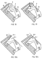
- an application spatula can also be used. Corresponding embodiments are shown in FIGS. 12, 13 and 14, with FIG. A representing the rest position and FIG. B the application position.
- the inner lip 33.1 (or manipulation part of the applicator 30.2, FIG. 1) is designed as a deflectable spatula 35, and the outer lip 33.2 is rigid, as in the previously described embodiments with an application roller.
- An embodiment with a spatula has the advantage that the outlet gap is well sealed in the idle state.
- the cutting process ie in the application position
- the cutting angle is defined via the fixed outer lip 33.2 and the blade contact surface.
- the fixed outer lip 33.2 can be part of the blade body, for example.
- the spatula (35.1, Fig. 12) can be designed to be elastic in such a way that it closes the feed channel in the rest position (Fig. 12a), but is deflected in the application position and exposes the opening of the feed channel (Fig. 12b) and due to the elastic properties the material is moved back to the rest position.
- the spatula (35.2, Fig. 13) can also be hinged to the applicator (FIG. 13), again closing the feed channel in the rest position (FIG. 13a), deflected into the application position (Fig. 13b) and For example, is brought back to the rest position by spring force.
- the embodiment shown in Figure 14 has on a hinged spatula 35.3 a rotatably mounted or rigid application roller 3 ', which takes over the function of distributing the preparation on the skin.
- a movable application lip can also be used in connection with the action of the feed device (pump).
- FIGS. 15, 16 and 17 Corresponding embodiments are shown in FIGS. 15, 16 and 17 , again in the rest position (FIG. A) and in the application position (FIG. B). All variants with movable application lips have at least the same advantages as the variants with rigid outer lips and application rollers, and further advantages can also be achieved with variants of the lip design.
- the outer lip 36.1 of the variant shown in FIG. 15 is elastic. It is swung out of its rest position on the application roller 3 by the pump pressure and moved back into the rest position due to the elastic properties of its material.
- pivotable outer lips of this type it is possible to regulate the amount of fluid exiting greatly via the pressure of the application pump, the fluid exiting regulating the outlet gap outside the rest position. With deflectable lips, the discharge quantity can be controlled over a wide range by the pump pressure.
- the pump pressure must first overcome the spring pressure of the lip in its basic position before the fluid can escape to the outside. Only the contact pressure on the skin has to be taken into account, which counteracts the pump pressure.
- the variant shown in FIG. 17 has a manually displaceable outer lip 36.3, with the aid of which the fluid supply can be opened, closed and regulated manually.
- the outlet opening is not self-regulating, the opening torque can be determined independently of the pump pressure.
- the lower part of the application head can be designed as a comb, so that the hair is offered to the blade in a nicely aligned manner due to a combing effect.
- Two corresponding exemplary embodiments with a comb 35 which is attached to the outer lip 33.2 are shown in FIGS . 18a and 18b .
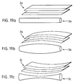
- the shaving head can be designed for shaving more or less flat or more rounded surfaces by using appropriately shaped application rollers or application spatulas and application openings and blades designed according to the function of the roller shape.
- FIGS. 19a to c show examples in which the course of the cutting blades essentially follows the course of the application roller (whereby such shapes can also be transferred to the application spatula). Deviations from this shape can also be useful, but the shape of the application roller should be functionally related to the blade shape.
- the possibilities outlined here only represent suggestions for further development and therefore only one application roller 3 and blades 2 are shown here in their relative arrangement.
- FIG. 19a to c show examples in which the course of the cutting blades essentially follows the course of the application roller (whereby such shapes can also be transferred to the application spatula). Deviations from this shape can also be useful, but the shape of the application roller should be functionally related to the blade shape.
- the possibilities outlined here only represent suggestions for further development and therefore only one application roller 3 and blades 2 are shown here in their
- FIG. 19a shows a typical arrangement with a cylindrical application roller 3a for shaving skin surfaces that can be deformed from the application roller into a flat surface
- FIG. 19b shows an arrangement with a convex application roller 3b for shaving concave surfaces such as depressions, for example in the armpits, which are no longer accessible with the linear blade
- FIG. 19c shows an arrangement with a concave application roller 3c for shaving convex surfaces such as elevations, for example on the larynx, in which the linear blade would entail an increased risk of injury.
- the application gap is also formally assigned to the application roll, the functional connection between the supply of the fluid and its distribution also remaining the same here. Embodiments designed in this way can work on more rounded shaving surfaces.
Landscapes
- Life Sciences & Earth Sciences (AREA)
- Forests & Forestry (AREA)
- Engineering & Computer Science (AREA)
- Mechanical Engineering (AREA)
- Dry Shavers And Clippers (AREA)
Applications Claiming Priority (2)
| Application Number | Priority Date | Filing Date | Title |
|---|---|---|---|
| CH209790 | 1990-06-22 | ||
| CH2097/90 | 1990-06-22 |
Publications (2)
| Publication Number | Publication Date |
|---|---|
| EP0463992A1 true EP0463992A1 (fr) | 1992-01-02 |
| EP0463992B1 EP0463992B1 (fr) | 1994-03-16 |
Family
ID=4225814
Family Applications (1)
| Application Number | Title | Priority Date | Filing Date |
|---|---|---|---|
| EP91810461A Expired - Lifetime EP0463992B1 (fr) | 1990-06-22 | 1991-06-17 | Rasoir mécanique |
Country Status (7)
| Country | Link |
|---|---|
| US (1) | US5168628A (fr) |
| EP (1) | EP0463992B1 (fr) |
| JP (1) | JPH04231909A (fr) |
| AT (1) | ATE102861T1 (fr) |
| DE (1) | DE59101190D1 (fr) |
| DK (1) | DK0463992T3 (fr) |
| ES (1) | ES2053309T3 (fr) |
Cited By (13)
| Publication number | Priority date | Publication date | Assignee | Title |
|---|---|---|---|---|
| EP0495754A1 (fr) * | 1991-01-17 | 1992-07-22 | Kai Industries Co. Ltd. | Cartouche d'échange pour un rasoir avec un applicateur |
| GB2282773A (en) * | 1993-10-13 | 1995-04-19 | Giles Norman Lantos | Safety-razor |
| WO1995031121A1 (fr) * | 1994-05-16 | 1995-11-23 | Bramlage Gmbh | Recipient pour cosmetique |
| US5903979A (en) * | 1994-07-13 | 1999-05-18 | The Gillette Company | Safety razors |
| WO2008152601A1 (fr) * | 2007-06-12 | 2008-12-18 | The Gillette Company | Rasoir à distribution de liquide commandée par une pompe actionnée par pivotement |
| WO2008152594A1 (fr) | 2007-06-12 | 2008-12-18 | The Gillette Company | Rasoir à distribution de liquide actionnable manuellement |
| WO2011073858A1 (fr) * | 2009-12-15 | 2011-06-23 | Koninklijke Philips Electronics N.V. | Dispositif de rasage |
| WO2012058214A1 (fr) * | 2010-10-28 | 2012-05-03 | The Gillette Company | Applicateur comportant un déflecteur pour un dispositif dépilation |
| WO2012058505A1 (fr) * | 2010-10-28 | 2012-05-03 | The Gillette Company | Applicateur avec un déflecteur pour un dispositif d'épilation des poils |
| WO2012058499A1 (fr) * | 2010-10-28 | 2012-05-03 | The Gillette Company | Pompe pour rasoir à distributeur de liquide |
| CN102452096A (zh) * | 2010-10-28 | 2012-05-16 | 吉列公司 | 用于分配液体的毛发移除装置的柄部 |
| CN103987501A (zh) * | 2011-12-09 | 2014-08-13 | 吉列公司 | 用于个人护理器具的流体施用装置 |
| EP3658342A4 (fr) * | 2018-07-08 | 2020-12-30 | Youti Kuo | Dispositif applicateur de rasage |
Families Citing this family (84)
| Publication number | Priority date | Publication date | Assignee | Title |
|---|---|---|---|---|
| US5402574A (en) * | 1994-05-20 | 1995-04-04 | Milner; Joshua P. | Shaving apparatus |
| US5678316A (en) * | 1995-12-15 | 1997-10-21 | Warner-Lambert Company | Disposable razor |
| EP0857101A1 (fr) * | 1996-08-29 | 1998-08-12 | Koninklijke Philips Electronics N.V. | Systeme et appareil d'epilation et cartouche associee |
| GB2342884A (en) * | 1998-10-23 | 2000-04-26 | Anita Casali | Razor with self-contained lubricant |
| DE19907224C2 (de) * | 1999-02-19 | 2001-02-22 | Braun Gmbh | Flüssigkeitsbehälter |
| DE19907025A1 (de) | 1999-02-19 | 2000-08-31 | Braun Gmbh | Haarentfernungsgerät |
| US6167625B1 (en) | 1999-05-18 | 2001-01-02 | Warner-Lambert Company | Shaving implement |
| EP1304196B1 (fr) * | 2001-10-22 | 2005-03-09 | Eveready Battery Company, Inc. | Dispositif de rasage |
| WO2003068466A1 (fr) * | 2002-02-13 | 2003-08-21 | Matsushita Electric Works, Ltd. | Dispositif permettant d'enlever les poils au moyen d'un applicateur de lotion |
| US6763590B2 (en) | 2002-10-21 | 2004-07-20 | Eveready Battery Company, Inc. | Razor assembly having a clutch controlled shaving aid delivery system |
| US6986207B2 (en) * | 2003-01-24 | 2006-01-17 | Ali Saban Selek | Single-use disposable shaving set |
| WO2004091870A1 (fr) * | 2003-04-07 | 2004-10-28 | Eveready Battery Company, Inc. | Systeme de distribution de produit de rasage destine a un rasoir humide |
| WO2004096504A1 (fr) * | 2003-04-30 | 2004-11-11 | Eisho Hujibe | Dispositif d'administration d'un liquide facilitant le rasage |
| JP4599047B2 (ja) * | 2003-09-30 | 2010-12-15 | 株式会社貝印刃物開発センター | 剃刀 |
| US6925716B2 (en) | 2003-12-04 | 2005-08-09 | Eveready Battery Company, Inc. | Shaving apparatus |
| US7043841B2 (en) * | 2003-12-04 | 2006-05-16 | Eveready Battery Co., Inc. | Shaving apparatus |
| US6964097B2 (en) | 2003-12-04 | 2005-11-15 | Eveready Battery Company, Inc. | Shaving apparatus |
| US7121754B2 (en) * | 2003-12-08 | 2006-10-17 | Eveready Battery Company, Inc. | Shaving apparatus with pivot-actuated valve for delivery of shaving aid material |
| US6910274B1 (en) * | 2003-12-16 | 2005-06-28 | Eveready Battery Company, Inc. | Shaving apparatus |
| US6886254B1 (en) | 2003-12-16 | 2005-05-03 | Eveready Battery Company, Inc. | Shaving apparatus |
| US20050138814A1 (en) * | 2003-12-30 | 2005-06-30 | Eveready Battery Company, Inc. | Shaving apparatus with shaving aid material dispenser |
| US7137203B2 (en) * | 2003-12-30 | 2006-11-21 | Eveready Battery Company, Inc. | Shaving apparatus |
| US7419322B2 (en) * | 2004-03-10 | 2008-09-02 | Poly-D Llc | Fluid dispensing device with metered delivery |
| US8061566B2 (en) * | 2007-04-26 | 2011-11-22 | Sealed Air Corporation (Us) | Metering dispensing system with improved valving to prevent accidental dispensing of liquid therefrom |
| US7997454B2 (en) * | 2007-04-26 | 2011-08-16 | Sealed Air Corporation (Us) | Metering dispensing system with improved valving to prevent accidental dispensing of liquid therefrom |
| US7140115B2 (en) * | 2004-05-10 | 2006-11-28 | Greene Todd M | Shaving apparatus with wheel |
| US20060080837A1 (en) * | 2004-10-20 | 2006-04-20 | Robert Johnson | Shaving razors and cartridges |
| DE102004059517A1 (de) * | 2004-12-10 | 2006-06-14 | Mahran Wanli | Rasierer und Verfahren zu seiner Herstellung |
| WO2008073879A1 (fr) * | 2006-12-11 | 2008-06-19 | Poly-D, Llc | Dispositif en éponge présentant une construction combinée de matériaux en cellulose et d'uréthane |
| MX2009006123A (es) * | 2006-12-11 | 2009-09-18 | Poly D Llc | Bolsa erguida de distribucion. |
| WO2008100747A1 (fr) * | 2007-02-09 | 2008-08-21 | Poly-D, Llc | Pochette souple de distribution de dosage avec une buse de pulvérisation |
| US20080190961A1 (en) * | 2007-02-09 | 2008-08-14 | Poly-D, Llc | Metered dosing container with independently deformable internal bladder |
| EP2114787A4 (fr) * | 2007-02-13 | 2012-01-04 | Sealed Air Corp | Contenant ayant un réservoir secondaire pour un dosage mesuré d'additifs |
| US20080203114A1 (en) * | 2007-02-23 | 2008-08-28 | Poly-D, Llc | Fluid dispenser with docking station |
| WO2008103896A2 (fr) * | 2007-02-23 | 2008-08-28 | Poly-D, Llc | Nettoyeur de surface équipé d'un tampon rotatif |
| US8136700B2 (en) * | 2007-02-23 | 2012-03-20 | Sealed Air Corporation (Us) | Dual chambered fluid dispenser with mixing chamber |
| US20080205970A1 (en) * | 2007-02-23 | 2008-08-28 | Poly-D, Llc | Toothbrush with integrated toothpaste delivery |
| US8152400B2 (en) * | 2007-02-23 | 2012-04-10 | Sealed Air Corporation (Us) | Surface cleaner with removable wand |
| JP5021771B2 (ja) * | 2007-03-14 | 2012-09-12 | ポリィ−ディー・エルエルシー | デュアルポンプシステムを備えた分配装置 |
| US8292120B2 (en) * | 2007-03-26 | 2012-10-23 | Sealed Air Corporation (Us) | Hanging liquid dispenser |
| ES2358035T3 (es) * | 2007-04-26 | 2011-05-05 | Brian Arthur Steinhobel | Maquinilla de afeitar. |
| FR2924044B1 (fr) * | 2007-11-28 | 2010-05-28 | Lindal France | Rasoir manuel a tete de rasage pivotante |
| WO2009094222A1 (fr) * | 2008-01-23 | 2009-07-30 | Poly-D, Llc | Rasoir muni d'un distributeur intégré de traitements de rasage |
| DE102008009082B4 (de) * | 2008-02-14 | 2017-08-31 | Peiniger Gmbh | Vorrichtung sowie Schneidwerkzeug für die abtragende Hautbehandlung |
| US20090320293A1 (en) * | 2008-03-19 | 2009-12-31 | Sean Peter Clarke | Manually Actuable Liquid Dispensing Razor With Degradable Shaving Aid |
| WO2009131670A2 (fr) * | 2008-04-21 | 2009-10-29 | Poly-D, Llc | Ensemble distributeur de cartouche remplaçable |
| KR20110069090A (ko) * | 2008-10-17 | 2011-06-22 | 더 질레트 컴퍼니 | 유체 분배식 모발 제거 장치 |
| US9744680B2 (en) | 2008-10-17 | 2017-08-29 | The Gillette Company | Fluid dispensing hair removal device |
| EP2218437A1 (fr) * | 2009-02-17 | 2010-08-18 | The Gillette Company | Compositions de rasage comprenant des particules chargées de colorant |
| US8745877B2 (en) * | 2009-03-23 | 2014-06-10 | The Gillette Company | Manually actuable liquid dispensing razor |
| US8826543B2 (en) * | 2009-03-23 | 2014-09-09 | The Gillette Company | Manually actuable liquid dispensing razor |
| WO2011005975A1 (fr) | 2009-07-08 | 2011-01-13 | Poly-D, Llc | Système de distribution doseur à ensemble pompe monobloc |
| EP2547493B1 (fr) * | 2010-03-15 | 2015-10-07 | The Gillette Company | Dispositif de distribution de liquide comprenant une pompe péristaltique |
| WO2011115971A1 (fr) * | 2010-03-15 | 2011-09-22 | The Gillette Company | Dispositif d'élimination des poils |
| EP2558252B1 (fr) * | 2010-04-15 | 2015-07-29 | The Gillette Company | Dispositif de retrait de poils à distribution de fluide |
| US8720072B2 (en) | 2010-08-11 | 2014-05-13 | Thomas J. Bucco | Razor with three-axis multi-position capability |
| RU2013120441A (ru) * | 2010-10-27 | 2014-12-10 | Дзе Жиллетт Компани | Устройство для дозирования беспенной увлажняющей композиции |
| CN102452094A (zh) | 2010-10-28 | 2012-05-16 | 吉列公司 | 分配液体的毛发移除套件 |
| CN103189169B (zh) * | 2010-10-28 | 2015-09-09 | 吉列公司 | 具有用于毛发移除装置的导流板的施用装置 |
| CN102452095B (zh) * | 2010-10-28 | 2014-10-29 | 吉列公司 | 用于分配液体的毛发移除装置的施用装置 |
| CN102452088B (zh) * | 2010-10-28 | 2015-07-01 | 吉列公司 | 具有刀片架保持覆盖件的毛发移除装置 |
| CN102452092B (zh) | 2010-10-28 | 2015-04-01 | 吉列公司 | 分配液体的毛发移除装置 |
| EP2974627B1 (fr) * | 2010-12-13 | 2018-06-20 | Novis AG | Appareil pour extraire du jus et la pulpe de fruits ou de légumes |
| JP5860707B2 (ja) * | 2011-05-18 | 2016-02-16 | 株式会社貝印刃物開発センター | 首振り式剃刀 |
| CA2856750C (fr) * | 2011-12-09 | 2017-10-17 | The Gillette Company | Rasoir distributeur de fluide |
| US9283685B2 (en) | 2012-07-26 | 2016-03-15 | Shavelogic, Inc. | Pivoting razors |
| US9486930B2 (en) | 2012-09-27 | 2016-11-08 | Shavelogic, Inc. | Shaving systems |
| WO2014051842A1 (fr) | 2012-09-27 | 2014-04-03 | Shavelogic, Inc. | Systèmes de rasage |
| WO2014051843A1 (fr) | 2012-09-28 | 2014-04-03 | Shavelogic, Inc. | Systèmes de rasage |
| US9623575B2 (en) | 2012-12-18 | 2017-04-18 | Shavelogic, Inc. | Shaving systems |
| US20150158192A1 (en) | 2013-12-09 | 2015-06-11 | Shavelogic, Inc. | Multi-material pivot return for shaving systems |
| US11325270B2 (en) | 2014-03-21 | 2022-05-10 | Sl Ip Company Llc | Metal spring return and method |
| USD874061S1 (en) | 2018-03-30 | 2020-01-28 | The Gillette Company Llc | Shaving razor cartridge |
| JP2021516102A (ja) | 2018-03-30 | 2021-07-01 | ザ ジレット カンパニー リミテッド ライアビリティ カンパニーThe Gillette Company Llc | 枢動部分を有するかみそりハンドル |
| EP3552780B1 (fr) | 2018-03-30 | 2021-01-27 | The Gillette Company LLC | Cartouche de rasoir |
| CN111819048A (zh) | 2018-03-30 | 2020-10-23 | 吉列有限责任公司 | 具有枢转部分的剃刀柄部 |
| EP3774227A1 (fr) | 2018-03-30 | 2021-02-17 | The Gillette Company LLC | Manche de rasoir avec éléments mobiles |
| JP7090727B2 (ja) | 2018-03-30 | 2022-06-24 | ザ ジレット カンパニー リミテッド ライアビリティ カンパニー | 枢動部分を有するかみそりハンドル |
| CN111819050B (zh) | 2018-03-30 | 2022-10-04 | 吉列有限责任公司 | 具有可移动构件的剃刀柄部 |
| US11607820B2 (en) | 2018-03-30 | 2023-03-21 | The Gillette Company Llc | Razor handle with movable members |
| EP3774224A1 (fr) | 2018-03-30 | 2021-02-17 | The Gillette Company LLC | Poignée de rasoir comprenant une partie rotative |
| US11123888B2 (en) | 2018-03-30 | 2021-09-21 | The Gillette Company Llc | Razor handle with a pivoting portion |
| US10864647B2 (en) * | 2019-01-22 | 2020-12-15 | Reyna Alvarez | Adjustable razor and method of use |
| KR102289030B1 (ko) * | 2019-09-11 | 2021-08-11 | 주식회사 도루코 | 면도기 카트리지 및 이를 이용한 면도기 조립체 |
Citations (8)
| Publication number | Priority date | Publication date | Assignee | Title |
|---|---|---|---|---|
| GB488143A (en) * | 1937-09-18 | 1938-07-01 | Arthur James Wakeford | Improvements in or relating to safety razors |
| GB490808A (en) * | 1937-02-17 | 1938-08-17 | Manuel Andres Y Gonzalez | Improvements in or relating to razors, particularly safety razors |
| CH279398A (de) * | 1947-10-29 | 1951-11-30 | Noel Davies James | Rasierapparat mit Rasierflüssigkeit. |
| GB879736A (en) * | 1959-01-20 | 1961-10-11 | Baruch Shalev | Improvements in safety razors |
| US3139683A (en) * | 1963-04-02 | 1964-07-07 | Waldman Joseph | Safety razor with fluid distributing manifold |
| US4314404A (en) * | 1980-02-20 | 1982-02-09 | Ruiz Rene A | Razor with pre-wetting or capillarizer system |
| FR2494603A1 (fr) * | 1980-11-26 | 1982-05-28 | Normos Norbert | Dispositif de pulverisation de fluides |
| EP0418483A1 (fr) * | 1989-09-21 | 1991-03-27 | Wilkinson Sword Gesellschaft mit beschränkter Haftung | Tête de rasage, en particulier ensemble à lames de rasoir |
Family Cites Families (9)
| Publication number | Priority date | Publication date | Assignee | Title |
|---|---|---|---|---|
| US1892836A (en) * | 1932-04-29 | 1933-01-03 | George R Harvey | Combination razor and shaving brush |
| US2861338A (en) * | 1955-09-20 | 1958-11-25 | Edward R Boland | Lather-applying safety razors |
| US2866265A (en) * | 1956-11-02 | 1958-12-30 | John D Kells | Combination safety razor and lather dispenser having telescopically related head and dispensing assemblies |
| US3417468A (en) * | 1965-07-27 | 1968-12-24 | Miyauchi Hideo | Razor |
| US4074429A (en) * | 1976-08-23 | 1978-02-21 | Roberts Thomas G | Novel lathering device and razor assembly |
| US4023269A (en) * | 1976-08-30 | 1977-05-17 | Lopez Jr Lorenzo | Shaving device |
| US4077119A (en) * | 1977-02-16 | 1978-03-07 | Jose Manuel Sellera | Shaving device |
| US4562644A (en) * | 1984-08-10 | 1986-01-07 | Hitchens Peter B | Lubricant-applying safety razor |
| FR2605923A1 (fr) * | 1986-10-31 | 1988-05-06 | Kolacinski Patrice | Rasoir mecanique incorpore d'un doseur de produit de rasage |
-
1991
- 1991-06-17 EP EP91810461A patent/EP0463992B1/fr not_active Expired - Lifetime
- 1991-06-17 AT AT91810461T patent/ATE102861T1/de not_active IP Right Cessation
- 1991-06-17 ES ES91810461T patent/ES2053309T3/es not_active Expired - Lifetime
- 1991-06-17 DE DE91810461T patent/DE59101190D1/de not_active Expired - Fee Related
- 1991-06-17 DK DK91810461.3T patent/DK0463992T3/da active
- 1991-06-19 US US07/718,557 patent/US5168628A/en not_active Expired - Fee Related
- 1991-06-21 JP JP3150137A patent/JPH04231909A/ja active Pending
Patent Citations (8)
| Publication number | Priority date | Publication date | Assignee | Title |
|---|---|---|---|---|
| GB490808A (en) * | 1937-02-17 | 1938-08-17 | Manuel Andres Y Gonzalez | Improvements in or relating to razors, particularly safety razors |
| GB488143A (en) * | 1937-09-18 | 1938-07-01 | Arthur James Wakeford | Improvements in or relating to safety razors |
| CH279398A (de) * | 1947-10-29 | 1951-11-30 | Noel Davies James | Rasierapparat mit Rasierflüssigkeit. |
| GB879736A (en) * | 1959-01-20 | 1961-10-11 | Baruch Shalev | Improvements in safety razors |
| US3139683A (en) * | 1963-04-02 | 1964-07-07 | Waldman Joseph | Safety razor with fluid distributing manifold |
| US4314404A (en) * | 1980-02-20 | 1982-02-09 | Ruiz Rene A | Razor with pre-wetting or capillarizer system |
| FR2494603A1 (fr) * | 1980-11-26 | 1982-05-28 | Normos Norbert | Dispositif de pulverisation de fluides |
| EP0418483A1 (fr) * | 1989-09-21 | 1991-03-27 | Wilkinson Sword Gesellschaft mit beschränkter Haftung | Tête de rasage, en particulier ensemble à lames de rasoir |
Cited By (20)
| Publication number | Priority date | Publication date | Assignee | Title |
|---|---|---|---|---|
| US5283952A (en) * | 1991-01-17 | 1994-02-08 | Kai Industries Co. Ltd. | Replacement cartridge for a shaver with an applicator |
| EP0495754A1 (fr) * | 1991-01-17 | 1992-07-22 | Kai Industries Co. Ltd. | Cartouche d'échange pour un rasoir avec un applicateur |
| GB2282773A (en) * | 1993-10-13 | 1995-04-19 | Giles Norman Lantos | Safety-razor |
| WO1995031121A1 (fr) * | 1994-05-16 | 1995-11-23 | Bramlage Gmbh | Recipient pour cosmetique |
| US5903979A (en) * | 1994-07-13 | 1999-05-18 | The Gillette Company | Safety razors |
| CN101687328B (zh) * | 2007-06-12 | 2013-03-13 | 吉列公司 | 可手动致动的液体分配剃刀 |
| WO2008152601A1 (fr) * | 2007-06-12 | 2008-12-18 | The Gillette Company | Rasoir à distribution de liquide commandée par une pompe actionnée par pivotement |
| WO2008152594A1 (fr) | 2007-06-12 | 2008-12-18 | The Gillette Company | Rasoir à distribution de liquide actionnable manuellement |
| CN101687329B (zh) * | 2007-06-12 | 2012-04-25 | 吉列公司 | 可枢转启动的泵驱动的液体分配剃刀 |
| AU2008263479B2 (en) * | 2007-06-12 | 2013-11-28 | The Gillette Company Llc | Manually actuable liquid dispensing razor |
| WO2011073858A1 (fr) * | 2009-12-15 | 2011-06-23 | Koninklijke Philips Electronics N.V. | Dispositif de rasage |
| US9375856B2 (en) | 2009-12-15 | 2016-06-28 | Koninklijke Philips N.V. | Shaving device |
| WO2012058505A1 (fr) * | 2010-10-28 | 2012-05-03 | The Gillette Company | Applicateur avec un déflecteur pour un dispositif d'épilation des poils |
| CN102452096A (zh) * | 2010-10-28 | 2012-05-16 | 吉列公司 | 用于分配液体的毛发移除装置的柄部 |
| WO2012058499A1 (fr) * | 2010-10-28 | 2012-05-03 | The Gillette Company | Pompe pour rasoir à distributeur de liquide |
| RU2533306C1 (ru) * | 2010-10-28 | 2014-11-20 | Дзе Жиллетт Компани | Устройство для удаления волос, содержащее аппликатор со щитком |
| WO2012058214A1 (fr) * | 2010-10-28 | 2012-05-03 | The Gillette Company | Applicateur comportant un déflecteur pour un dispositif dépilation |
| CN103987501A (zh) * | 2011-12-09 | 2014-08-13 | 吉列公司 | 用于个人护理器具的流体施用装置 |
| CN103987501B (zh) * | 2011-12-09 | 2016-06-22 | 吉列公司 | 用于个人护理器具的流体施用装置 |
| EP3658342A4 (fr) * | 2018-07-08 | 2020-12-30 | Youti Kuo | Dispositif applicateur de rasage |
Also Published As
| Publication number | Publication date |
|---|---|
| DK0463992T3 (da) | 1994-04-05 |
| JPH04231909A (ja) | 1992-08-20 |
| ES2053309T3 (es) | 1994-07-16 |
| DE59101190D1 (de) | 1994-04-21 |
| ATE102861T1 (de) | 1994-04-15 |
| US5168628A (en) | 1992-12-08 |
| EP0463992B1 (fr) | 1994-03-16 |
Similar Documents
| Publication | Publication Date | Title |
|---|---|---|
| EP0463992B1 (fr) | Rasoir mécanique | |
| EP0605397B1 (fr) | Tête de rasoir, particulièrement unité de lames | |
| DE3829395C2 (de) | Vorrichtung zum Auftragen eines Produkts auf eine Oberfläche, insbesondere Applikatorvorrichtung für ein kosmetisches, insbesondere depilatorisches Produkt | |
| AT395816B (de) | Vorrichtung zur manuellen hautmassage und zum gleichzeitigen auftragen eines fluessigen oder pastenartigen produktes auf die haut | |
| DE2260724C3 (de) | Auftragsvorrichtung für ein in einem Behälter untergebrachtes kosmetisches Präparat | |
| DE8333236U1 (de) | Streicheinrichtung zur Beschichtung laufender Warenbahnen | |
| EP0155616A2 (fr) | Récipient muni d'un dispositif pour l'application de liquide sur une surface | |
| EP1784096A2 (fr) | Applicateur | |
| CH682041A5 (en) | Applicator for thin film cosmetic or pharmaceutical prepn. on skin - has storage device in handgrip with application by means of rotatable and pivotable roller | |
| EP0901839B1 (fr) | Dispositif pour l'application de fluides sur un substrat | |
| DE1807236A1 (de) | Mechanischer Rasierapparat | |
| EP2272393A1 (fr) | Applicateur de colorant pour cheveux | |
| DE60025346T2 (de) | Bandspender | |
| EP0268860B1 (fr) | Dispositif pour le maniement de liquides pour traiter les cheveux ou pour une utilisation similaire | |
| DE2055159A1 (de) | Druckdose, insbesondere Spraydose | |
| DE2050458C3 (de) | Handgerat zum Auftragen flussigen Materials | |
| DE4326593C2 (de) | Druckfarbenzuführungseinrichtung | |
| DE102004048164B3 (de) | Vorrichtung zum Auftragen von Rasierschaum, Rasiercreme, Rasiergel, Konditionierflüssigkeit oder dergleichen Konditioniermittel auf die Haut,Kartusche dafür, sowie Trockenrasiergerät und Epiliergerät mit einer solchen Vorrichtung | |
| DE19963065B4 (de) | Vorrichtung zum Auftragen eines Haarbehandlungsmittels und Verwendung der Vorrichtung | |
| DE2801551C3 (de) | Druckgerät mit einem Betätigungshebel, einer Druckstange o.dgl | |
| DE10029458A1 (de) | Vorrichtung zum Auftragen von Klebstoff auf einen Buchrücken | |
| DE4106578A1 (de) | Fluessigkeitsauftraeger | |
| DE2122515C3 (de) | Abschwenkbare Reinigungsvorrichtung für den Gummizylinder einer Büro-Offset-Druckmaschine | |
| DE504696C (de) | Stabfoermiges Nagelpflegegeraet | |
| DE684451C (de) | Vorrichtung fuer die Hautmassage |
Legal Events
| Date | Code | Title | Description |
|---|---|---|---|
| PUAI | Public reference made under article 153(3) epc to a published international application that has entered the european phase |
Free format text: ORIGINAL CODE: 0009012 |
|
| AK | Designated contracting states |
Kind code of ref document: A1 Designated state(s): AT BE CH DE DK ES FR GB GR IT LI LU NL SE |
|
| RAP1 | Party data changed (applicant data changed or rights of an application transferred) |
Owner name: KAI INDUSTRIES CO. LTD. |
|
| 17P | Request for examination filed |
Effective date: 19920624 |
|
| 17Q | First examination report despatched |
Effective date: 19921029 |
|
| GRAA | (expected) grant |
Free format text: ORIGINAL CODE: 0009210 |
|
| AK | Designated contracting states |
Kind code of ref document: B1 Designated state(s): AT BE CH DE DK ES FR GB GR IT LI LU NL SE |
|
| REF | Corresponds to: |
Ref document number: 102861 Country of ref document: AT Date of ref document: 19940415 Kind code of ref document: T |
|
| ITF | It: translation for a ep patent filed |
Owner name: JACOBACCI CASETTA & PERANI S.P.A. |
|
| REG | Reference to a national code |
Ref country code: DK Ref legal event code: T3 |
|
| REF | Corresponds to: |
Ref document number: 59101190 Country of ref document: DE Date of ref document: 19940421 |
|
| GBT | Gb: translation of ep patent filed (gb section 77(6)(a)/1977) |
Effective date: 19940413 |
|
| ET | Fr: translation filed | ||
| REG | Reference to a national code |
Ref country code: ES Ref legal event code: FG2A Ref document number: 2053309 Country of ref document: ES Kind code of ref document: T3 |
|
| EPTA | Lu: last paid annual fee | ||
| REG | Reference to a national code |
Ref country code: GR Ref legal event code: FG4A Free format text: 3011937 |
|
| PLBE | No opposition filed within time limit |
Free format text: ORIGINAL CODE: 0009261 |
|
| STAA | Information on the status of an ep patent application or granted ep patent |
Free format text: STATUS: NO OPPOSITION FILED WITHIN TIME LIMIT |
|
| EAL | Se: european patent in force in sweden |
Ref document number: 91810461.3 |
|
| 26N | No opposition filed | ||
| PGFP | Annual fee paid to national office [announced via postgrant information from national office to epo] |
Ref country code: GR Payment date: 19950417 Year of fee payment: 5 |
|
| PGFP | Annual fee paid to national office [announced via postgrant information from national office to epo] |
Ref country code: LU Payment date: 19950501 Year of fee payment: 5 |
|
| PGFP | Annual fee paid to national office [announced via postgrant information from national office to epo] |
Ref country code: BE Payment date: 19950510 Year of fee payment: 5 |
|
| PGFP | Annual fee paid to national office [announced via postgrant information from national office to epo] |
Ref country code: GB Payment date: 19950606 Year of fee payment: 5 |
|
| PGFP | Annual fee paid to national office [announced via postgrant information from national office to epo] |
Ref country code: ES Payment date: 19950615 Year of fee payment: 5 Ref country code: DK Payment date: 19950615 Year of fee payment: 5 |
|
| PGFP | Annual fee paid to national office [announced via postgrant information from national office to epo] |
Ref country code: SE Payment date: 19950616 Year of fee payment: 5 Ref country code: AT Payment date: 19950616 Year of fee payment: 5 |
|
| PGFP | Annual fee paid to national office [announced via postgrant information from national office to epo] |
Ref country code: FR Payment date: 19950628 Year of fee payment: 5 |
|
| PGFP | Annual fee paid to national office [announced via postgrant information from national office to epo] |
Ref country code: NL Payment date: 19950629 Year of fee payment: 5 |
|
| PGFP | Annual fee paid to national office [announced via postgrant information from national office to epo] |
Ref country code: DE Payment date: 19950829 Year of fee payment: 5 |
|
| PG25 | Lapsed in a contracting state [announced via postgrant information from national office to epo] |
Ref country code: LU Free format text: LAPSE BECAUSE OF NON-PAYMENT OF DUE FEES Effective date: 19960617 Ref country code: GB Effective date: 19960617 Ref country code: DK Effective date: 19960617 Ref country code: AT Effective date: 19960617 |
|
| REG | Reference to a national code |
Ref country code: DK Ref legal event code: EBP |
|
| PG25 | Lapsed in a contracting state [announced via postgrant information from national office to epo] |
Ref country code: SE Effective date: 19960618 Ref country code: ES Free format text: LAPSE BECAUSE OF THE APPLICANT RENOUNCES Effective date: 19960618 |
|
| PG25 | Lapsed in a contracting state [announced via postgrant information from national office to epo] |
Ref country code: BE Effective date: 19960630 |
|
| BERE | Be: lapsed |
Owner name: KAI INDUSTRIES CO. LTD Effective date: 19960630 |
|
| PG25 | Lapsed in a contracting state [announced via postgrant information from national office to epo] |
Ref country code: GR Free format text: THE PATENT HAS BEEN ANNULLED BY A DECISION OF A NATIONAL AUTHORITY Effective date: 19961231 |
|
| PG25 | Lapsed in a contracting state [announced via postgrant information from national office to epo] |
Ref country code: NL Effective date: 19970101 |
|
| REG | Reference to a national code |
Ref country code: GR Ref legal event code: MM2A Free format text: 3011937 |
|
| GBPC | Gb: european patent ceased through non-payment of renewal fee |
Effective date: 19960617 |
|
| PG25 | Lapsed in a contracting state [announced via postgrant information from national office to epo] |
Ref country code: FR Effective date: 19970228 |
|
| PG25 | Lapsed in a contracting state [announced via postgrant information from national office to epo] |
Ref country code: DE Effective date: 19970301 |
|
| EUG | Se: european patent has lapsed |
Ref document number: 91810461.3 |
|
| NLV4 | Nl: lapsed or anulled due to non-payment of the annual fee |
Effective date: 19970101 |
|
| REG | Reference to a national code |
Ref country code: FR Ref legal event code: ST |
|
| REG | Reference to a national code |
Ref country code: ES Ref legal event code: FD2A Effective date: 19991007 |
|
| PGFP | Annual fee paid to national office [announced via postgrant information from national office to epo] |
Ref country code: CH Payment date: 20030522 Year of fee payment: 13 |
|
| PG25 | Lapsed in a contracting state [announced via postgrant information from national office to epo] |
Ref country code: LI Free format text: LAPSE BECAUSE OF NON-PAYMENT OF DUE FEES Effective date: 20040630 Ref country code: CH Free format text: LAPSE BECAUSE OF NON-PAYMENT OF DUE FEES Effective date: 20040630 |
|
| REG | Reference to a national code |
Ref country code: CH Ref legal event code: PL |
|
| PG25 | Lapsed in a contracting state [announced via postgrant information from national office to epo] |
Ref country code: IT Free format text: LAPSE BECAUSE OF NON-PAYMENT OF DUE FEES;WARNING: LAPSES OF ITALIAN PATENTS WITH EFFECTIVE DATE BEFORE 2007 MAY HAVE OCCURRED AT ANY TIME BEFORE 2007. THE CORRECT EFFECTIVE DATE MAY BE DIFFERENT FROM THE ONE RECORDED. Effective date: 20050617 |