EP0460394B1 - Behälter mit Ausgiessvorrichtung - Google Patents
Behälter mit Ausgiessvorrichtung Download PDFInfo
- Publication number
- EP0460394B1 EP0460394B1 EP91106930A EP91106930A EP0460394B1 EP 0460394 B1 EP0460394 B1 EP 0460394B1 EP 91106930 A EP91106930 A EP 91106930A EP 91106930 A EP91106930 A EP 91106930A EP 0460394 B1 EP0460394 B1 EP 0460394B1
- Authority
- EP
- European Patent Office
- Prior art keywords
- container
- nozzle
- shaped element
- tip
- container according
- Prior art date
- Legal status (The legal status is an assumption and is not a legal conclusion. Google has not performed a legal analysis and makes no representation as to the accuracy of the status listed.)
- Expired - Lifetime
Links
- 239000011111 cardboard Substances 0.000 claims description 10
- 239000012528 membrane Substances 0.000 claims description 4
- 238000007789 sealing Methods 0.000 claims description 4
- 239000004033 plastic Substances 0.000 claims description 3
- 238000003475 lamination Methods 0.000 claims 1
- 239000011888 foil Substances 0.000 description 14
- 238000011161 development Methods 0.000 description 12
- 230000018109 developmental process Effects 0.000 description 12
- 239000011087 paperboard Substances 0.000 description 6
- 238000011109 contamination Methods 0.000 description 3
- 238000009826 distribution Methods 0.000 description 3
- 230000032258 transport Effects 0.000 description 3
- 239000000428 dust Substances 0.000 description 2
- 239000007788 liquid Substances 0.000 description 2
- 210000002445 nipple Anatomy 0.000 description 2
- 238000011084 recovery Methods 0.000 description 2
- 241000274582 Pycnanthus angolensis Species 0.000 description 1
- 238000004026 adhesive bonding Methods 0.000 description 1
- 238000004873 anchoring Methods 0.000 description 1
- 230000004323 axial length Effects 0.000 description 1
- 235000013361 beverage Nutrition 0.000 description 1
- 239000002131 composite material Substances 0.000 description 1
- 238000003780 insertion Methods 0.000 description 1
- 230000037431 insertion Effects 0.000 description 1
- 238000004519 manufacturing process Methods 0.000 description 1
- 239000000463 material Substances 0.000 description 1
- 238000000034 method Methods 0.000 description 1
- 239000008267 milk Substances 0.000 description 1
- 210000004080 milk Anatomy 0.000 description 1
- 235000013336 milk Nutrition 0.000 description 1
- 238000004806 packaging method and process Methods 0.000 description 1
- 239000000123 paper Substances 0.000 description 1
- 239000002985 plastic film Substances 0.000 description 1
- 229920006255 plastic film Polymers 0.000 description 1
- 239000000843 powder Substances 0.000 description 1
- 238000003825 pressing Methods 0.000 description 1
- 238000003860 storage Methods 0.000 description 1
Images

Classifications
-
- B—PERFORMING OPERATIONS; TRANSPORTING
- B65—CONVEYING; PACKING; STORING; HANDLING THIN OR FILAMENTARY MATERIAL
- B65D—CONTAINERS FOR STORAGE OR TRANSPORT OF ARTICLES OR MATERIALS, e.g. BAGS, BARRELS, BOTTLES, BOXES, CANS, CARTONS, CRATES, DRUMS, JARS, TANKS, HOPPERS, FORWARDING CONTAINERS; ACCESSORIES, CLOSURES, OR FITTINGS THEREFOR; PACKAGING ELEMENTS; PACKAGES
- B65D5/00—Rigid or semi-rigid containers of polygonal cross-section, e.g. boxes, cartons or trays, formed by folding or erecting one or more blanks made of paper
- B65D5/02—Rigid or semi-rigid containers of polygonal cross-section, e.g. boxes, cartons or trays, formed by folding or erecting one or more blanks made of paper by folding or erecting a single blank to form a tubular body with or without subsequent folding operations, or the addition of separate elements, to close the ends of the body
- B65D5/06—Rigid or semi-rigid containers of polygonal cross-section, e.g. boxes, cartons or trays, formed by folding or erecting one or more blanks made of paper by folding or erecting a single blank to form a tubular body with or without subsequent folding operations, or the addition of separate elements, to close the ends of the body with end-closing or contents-supporting elements formed by folding inwardly a wall extending from, and continuously around, an end of the tubular body
- B65D5/064—Rectangular containers having a body with gusset-flaps folded outwardly or adhered to the side or the top of the container
-
- B—PERFORMING OPERATIONS; TRANSPORTING
- B65—CONVEYING; PACKING; STORING; HANDLING THIN OR FILAMENTARY MATERIAL
- B65D—CONTAINERS FOR STORAGE OR TRANSPORT OF ARTICLES OR MATERIALS, e.g. BAGS, BARRELS, BOTTLES, BOXES, CANS, CARTONS, CRATES, DRUMS, JARS, TANKS, HOPPERS, FORWARDING CONTAINERS; ACCESSORIES, CLOSURES, OR FITTINGS THEREFOR; PACKAGING ELEMENTS; PACKAGES
- B65D5/00—Rigid or semi-rigid containers of polygonal cross-section, e.g. boxes, cartons or trays, formed by folding or erecting one or more blanks made of paper
- B65D5/42—Details of containers or of foldable or erectable container blanks
- B65D5/72—Contents-dispensing means
- B65D5/74—Spouts
- B65D5/746—Spouts formed separately from the container
Definitions
- the invention relates to a container with side walls, bottom and lid flaps, with a tip that can be folded over a folded edge to form a pouring opening, in which the tip, when folded over, rests with its surface against the container wall adjacent to the folded edge.
- Such a container is known from DE 37 20 240 A1.
- This container is known for the distribution of milk to the end user.
- the tip which is glued to the side wall surface during distribution, is bent up, an outer portion of the tip being torn open, so that a pouring opening is formed.
- This container is not resealable.
- the closure area is open, so that it is at risk of being contaminated.
- a container which has a nozzle-shaped element on one surface for forming a pouring opening, a closure nipple for receiving the nozzle-shaped element being provided on the adjacent wall.
- the nozzle-shaped element is arranged on the surface of the container and the nipple is provided on a cover wall to seal it.
- the arrangement of the nozzle-shaped element for forming the pouring opening on the surface of the container makes pouring difficult. If the container is open, there is also a risk that the closure area, which is then open at the top, will become dirty.
- Closure elements for cardboard beverage containers are known from EP 0 342 729 A1, in which a closure cap can be placed over a nozzle-shaped element to close the container.
- the nozzle-shaped element is exposed and is therefore subject to the risk of contamination.
- the container according to the invention has the advantage that the tip applied to the surface of the container during transport can be raised without tools, but only with the fingers.
- the nozzle-shaped element can be designed to be reclosable without difficulty, this closure can also be operated by hand, a tool is not necessary. Since the tip is turned over when not in use and lies against the surface of the container, the nozzle-shaped element being immersed in the recess in the container wall, the opening is protected against contamination. Furthermore, the nozzle-shaped element enables controlled pouring without the liquid emerging from the container in a gushing manner.
- the nozzle-shaped element is designed as a pouring element projecting over the surface of the tip, the packaging can nevertheless be shaped in such a way that it uses the space optimally, namely that there are no projecting elements in the unused state.
- the development according to claim 2 has the advantage that a tight connection between the nozzle-shaped element and the surface of the tip can easily be formed.
- the development according to claim 5 has the advantage that the container can be made very stable and rigid.
- the container is very insensitive to impact and pressure.
- the development according to claim 6 represents a preferred embodiment of the sealing of the recess with respect to the interior of the container.
- the filled container is delivered to the end user by locking the tip with the projection behind the edges of the elongated hole.
- the tip does not protrude beyond the circumference of the container. This is a very special space-saving option.
- the user can turn the tip over again and lock the nozzle-shaped element back into the recess.
- the container has an appealing exterior, namely by covering the recess.
- the recess is also protected by the tab.
- the development according to claim 9 has the advantage that the folding boxboard and the loose inner foil bag can be separated from one another without difficulty.
- the user is therefore provided with a container that is absolutely leak-proof due to the foil pouch, so it is suitable for liquids or powders.
- the folding boxboard gives the container the strength it needs for storage, transport and use.
- the end user is able to feed the cardboard portion of the container to the paper recovery, while the film portion, which is usually a plastic film, and the closure can be fed to the plastic recovery.
- This container has the great advantage that it is extremely environmentally friendly.
- an absolutely tight connection between the nozzle-shaped element, which is the pouring element, and the film bag can be produced particularly easily. This prevents leaks.
- the development according to claim 11 has the advantage that when the container is emptied, the bag does not collapse with a loose inner bag. Therefore, the danger is avoided that parts of the product to be removed remain in a bag behind a collapsed part of the bag. Complete emptying of the container is therefore very possible.
- the development according to claim 12 has the advantage that the container surface can be easily printed and shows an attractive appearance, so that the distribution is facilitated.
- the embodiment according to claim 13 has the advantage that the container bottom becomes very stiff, so that the container has an even higher strength and is easy to stack.
- the design according to claim 14 can ensure that the end user can easily see whether he is buying an originally packaged product.
- the container 1 has a cardboard box in the form of a cardboard box, which provides the stability of the container.
- a cardboard box in the form of a cardboard box, which provides the stability of the container.
- an inner foil bag is provided on the inside.
- the cardboard is film-coated on the inside.
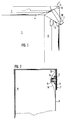
- the folding box board which in the exemplary embodiment shown is cuboid, has, as can best be seen from FIG. 6, a front wall 6, a first side wall 3 adjoining it on one side and a second side wall 24 adjoining the opposite edge.
- a rear wall 25 opposite the front wall 6 with an additional section 26 for gluing adjoins the second side wall.
- the blank has foldable cover flaps 4 and 5 which are firmly connected to the two side walls at the upper edge 27 of the walls described above. According to a first embodiment, these are formed in one piece with a tab 28 adjoining the front wall. The two tabs 4 and 5 are folded over in the usual way to close the top of the lid and glued to one another by a projecting section 29.
- the flap 28 has two fold lines 30, 31 which are formed by the corner points 32, 33 between the side wall 3 and the front wall and the associated flap 4 or the side wall 24 and the front wall 6 and the associated flap 5, and in the middle 34 of the upper edge of the tab 28 extend.
- the upper wall can also be closed in that both cover flaps 4, 5 have sections corresponding to the projecting section 29 and these are then connected to one another in the manner of a fin seam 10 (FIG. 1).
- tabs 35 to 38 are provided in the usual way, which are folded over one another and glued to one another for closing on the bottom.
- a perforation line 39 is provided between the projecting section 29 and the cover flap 4, which has the purpose of opening the upper side if desired by pulling off the section 29.
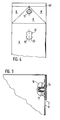
- a hole forming an opening 12 is provided in the front wall 6 at a predetermined distance from the edge 13. Furthermore, at a same predetermined distance from the edge 13 and on a straight line passing through the center of the opening 12 and extending perpendicular to the edge 13, in the triangular section 8 there is a nozzle-shaped element projecting outward from the surface of the triangular section 8 11 provided. The arrangement is chosen so that when the tip 7 is turned over, the element 11 dips into the opening 12 so that the tip can rest smoothly on the front wall 6.
- a foil pouch 14 receiving the product is arranged in the folding box.
- the socket-shaped element 11 has at its bottom end two ring-shaped flanges 16, 17 which tightly enclose the foil bag 14 and the section 8 of the tab 28 between them and thus provide a tight connection to Produce inside the foil bag 14.
- the foil bag 14 arranged in the outer carton is at its bottom end by providing one as a fin seam designated cross seal sealed.
- the resulting two ends on the sides of the transverse sealing seam are wiped between two superimposed tabs of the four bottom tabs 35 to 38, so that on the one hand there is a certain strength of the foil bag in the folding carton, but this is done by gripping the foil bag in the open top Opening can be pulled out of the outer carton.
- This embodiment of the container is made as follows.
- a folding box blank with the front wall 6, the side walls 3, 24 and a rear wall 25 and the associated tabs for forming a lid and a base is glued to form a box sleeve.
- a film tube is inserted into the box sleeve.
- the box sleeve, which is lined on the inside in this way, is placed over a form stamp.
- a hole is punched into the tab forming the underside of the tip 7 and into the part of the film tube lying against it.
- the nozzle-shaped element 11 is inserted into the hole.
- the nozzle-shaped element 11 has a circumferential flange 16 over approximately half the axial length.
- the nozzle-shaped element 11 is inserted into the hole from the outside until the flange 16 lies on the tip 7. Then the part of the nozzle-shaped element 11 protruding into the hollow tip 7 is folded over. Finally, the flange 16, the tip 7, the foil bag 14 and the folded part are connected to one another by the action of heat.
- the top of the foil bag is closed with a fin seam, the resulting tip of the foil bag is folded inwards.
- the flaps of the folding boxboard forming the lid are folded together and glued together.
- the resulting cardboard tip 7 is turned up against the front wall 6 of the container.
- the nozzle-shaped element 11 is pressed into the hole 12.
- the container or the foil bag 14 arranged in the container is filled from the bottom. After filling, the protruding end of the film bag 14 is spread and sealed to form a fin seam.
- a longitudinal flap 35 of the folding box is first laid inwards, then two film tips of the film bag are laid inwards, then the two dust flaps 36, 38 are placed on the bottom of the body. This results in the film tips being pinched between the side edge of the inner longitudinal tab 35 and the covering dust tabs 36, 38. Finally, the outer bottom tab 37 is folded inward and glued to the other tabs.
- the film bag is not loosely inserted into the folding boxboard, but instead a firm cardboard-film composite is used. Then, however, as shown in Fig. 3, the hole 12 must be covered by a bulged or deep-drawn film 18, leaving enough space in the container so that the nozzle-shaped element 11 without against the bulged film 18 to bump into the container.
- the opening 12 is closed by one or two tabs 19, 20 which can be folded over.
- the tabs 19, 20 are designed in the manner of a double-leaf gate.
- the flange 16 of the nozzle-shaped element 11 has a projection 21 shown in FIG. 5.
- the nozzle-shaped element 11 can be pressed in so far that the projection 21 engages behind the cut edges of the hole 12, whereby the tip 7 is anchored in its position parallel to the front wall 6.
- the hole 12 is designed as an elongated hole, as is shown in particular in FIG. 4. Its longitudinal axis coincides with the line connecting the center of the hole and the center of the nozzle 11. Then the projection 21 can reliably engage behind the longitudinal cut edge of the elongated hole.
- the design as an elongated hole has the advantage that the nozzle-shaped element 11 has some play in the vertical direction when it is inserted into the recess. This facilitates the insertion of the nozzle-shaped element 11 into the recess formed by the hole 12.
- a closure element 22 is provided for the nozzle-shaped element 11.
- This closure element is preferably screwed onto the nozzle-shaped element 11, but it can also be designed to be simply pluggable, in which case it must be held by friction.
- it is possible to close the nozzle-shaped element 11 with a thin membrane during manufacture, so that it is ensured that the product contained in the container cannot escape even during extensive transports. If this membrane is thin enough, the user can simply pierce it and remove the product.
- a simple closure element 22 can then be provided for closing the container at the end user.
- it is self-closing Lip provided at the end of the nozzle-shaped element 11 so that the membrane can be omitted.
- an inner cone 23 can be provided on the closure element 22, as shown in FIG. 5. This inner cone reliably seals the opening in the nozzle-shaped element 11.
- a label is attached to the tip 7 (as shown in FIG. 2) which extends parallel to the front wall 6 of the container and also partially covers the front wall 6. If this label is undamaged, the end user can be sure that it is an original package that has not yet been opened.
- the pouring out or pouring out of the product present in the container is carried out like in a jug.
- the reclosing process takes place simply by folding back the tip 7 until the projection 21 engages in the front wall 6.
Landscapes
- Engineering & Computer Science (AREA)
- Mechanical Engineering (AREA)
- Cartons (AREA)
- Closures For Containers (AREA)
- Control And Other Processes For Unpacking Of Materials (AREA)
Priority Applications (1)
| Application Number | Priority Date | Filing Date | Title |
|---|---|---|---|
| AT91106930T ATE81322T1 (de) | 1990-05-23 | 1991-04-29 | Behaelter mit ausgiessvorrichtung. |
Applications Claiming Priority (2)
| Application Number | Priority Date | Filing Date | Title |
|---|---|---|---|
| DE4016655A DE4016655C1 (enExample) | 1990-05-23 | 1990-05-23 | |
| DE4016655 | 1990-05-23 |
Publications (2)
| Publication Number | Publication Date |
|---|---|
| EP0460394A1 EP0460394A1 (de) | 1991-12-11 |
| EP0460394B1 true EP0460394B1 (de) | 1992-10-07 |
Family
ID=6407060
Family Applications (1)
| Application Number | Title | Priority Date | Filing Date |
|---|---|---|---|
| EP91106930A Expired - Lifetime EP0460394B1 (de) | 1990-05-23 | 1991-04-29 | Behälter mit Ausgiessvorrichtung |
Country Status (4)
| Country | Link |
|---|---|
| US (1) | US5133497A (enExample) |
| EP (1) | EP0460394B1 (enExample) |
| AT (1) | ATE81322T1 (enExample) |
| DE (2) | DE4016655C1 (enExample) |
Families Citing this family (12)
| Publication number | Priority date | Publication date | Assignee | Title |
|---|---|---|---|---|
| DE4119221C2 (de) * | 1991-06-11 | 1993-09-30 | Gerd Kueppersbusch | Transportverpackung für Schüttgut |
| GB2311772A (en) * | 1996-02-13 | 1997-10-08 | David Paul Fedorak | Spout for a container |
| GB2320709A (en) * | 1996-12-27 | 1998-07-01 | David Paul Fedorak | A spout for a container |
| JP2002096828A (ja) * | 2000-09-21 | 2002-04-02 | Shikoku Kakoki Co Ltd | 注出具付き容器およびその製造方法 |
| US6726088B2 (en) | 2000-10-30 | 2004-04-27 | Cascades Boxboard Inc. | Carton and carton blank |
| USD482279S1 (en) | 2000-10-30 | 2003-11-18 | Cascades Boxboard Inc. | Carton |
| US7770756B2 (en) * | 2002-05-17 | 2010-08-10 | Lbp Manufacturing, Inc. | Bulk container assembly |
| US6736289B2 (en) | 2002-05-17 | 2004-05-18 | Lbp Manufacturing, Inc. | Bulk container assembly |
| DE102004028767A1 (de) * | 2004-06-16 | 2005-12-29 | Georg Menshen Gmbh & Co. Kg | Verschluss einer Behälteröffnung |
| SE535780C2 (sv) * | 2010-02-19 | 2012-12-18 | Förpackning för flytande produkter | |
| DE102010054105A1 (de) * | 2010-12-10 | 2012-06-14 | Fraunhofer-Gesellschaft zur Förderung der angewandten Forschung e.V. | Verpackungsbehältnis für Flüssigkeiten |
| US20190084745A1 (en) * | 2017-09-19 | 2019-03-21 | Cameron Ernest Jabara | Disposable beverage container and method of operation |
Family Cites Families (16)
| Publication number | Priority date | Publication date | Assignee | Title |
|---|---|---|---|---|
| US3138315A (en) * | 1961-12-01 | 1964-06-23 | Frederick C Morrow | Closure for container |
| US3108732A (en) * | 1962-09-13 | 1963-10-29 | Corrugated Container Company | Disposable type pouring container package combination |
| SE332386C (sv) * | 1969-10-20 | 1972-05-23 | Tetra Pak Int | Öppningsanordning vid förpackningar |
| US3795359A (en) * | 1971-11-19 | 1974-03-05 | Tetra Pak Int | Parallellepipedic package |
| EP0018694B1 (en) * | 1979-05-08 | 1983-09-28 | Ab Tetra Pak | Packing containers with pouring spout |
| SE451064B (sv) * | 1981-12-30 | 1987-08-31 | Tetra Pak Int | Anordning vid forpackningsbehallare |
| DE3441865A1 (de) * | 1984-01-25 | 1985-07-25 | Dr. Scheuring GmbH, 4137 Rheurdt | Behaelter fuer fluessigkeiten |
| CH668237A5 (de) * | 1985-12-19 | 1988-12-15 | Sig Schweiz Industrieges | Zuschnitt fuer eine quaderpackung und quaderpackung. |
| SE453586B (sv) * | 1986-03-26 | 1988-02-15 | Tetra Pak Ab | Forpackningsbehallare forsedd med aterforslutbar oppningsanordning |
| FR2601332B1 (fr) * | 1986-07-11 | 1989-07-28 | Thiolat Sa | Boite pliante a couvercle homogene |
| US4754917A (en) * | 1986-07-29 | 1988-07-05 | International Paper Company | End closure construction for liquid containers |
| DE3720240A1 (de) * | 1987-06-19 | 1988-12-29 | Reinhard Siebrecht | Verpackungsgebinde |
| US4819865A (en) * | 1987-12-07 | 1989-04-11 | Elopak Systems A.G. | Low stress flat end closure arrangement for thermoplastic coated paperboard carton |
| DE3808303A1 (de) * | 1988-03-12 | 1989-09-21 | Pkl Verpackungssysteme Gmbh | Quaderfoermige flachgiebelpackung und verfahren zu deren herstellung |
| US4909434A (en) * | 1988-05-20 | 1990-03-20 | The Procter & Gamble Company | Moisture impervious carton having one-piece pouring spout sealed to innermost and outermost surfaces |
| DE3836069C1 (enExample) * | 1988-10-22 | 1989-12-07 | Henkel Kgaa, 4000 Duesseldorf, De |
-
1990
- 1990-05-23 DE DE4016655A patent/DE4016655C1/de not_active Expired - Lifetime
-
1991
- 1991-04-29 EP EP91106930A patent/EP0460394B1/de not_active Expired - Lifetime
- 1991-04-29 AT AT91106930T patent/ATE81322T1/de not_active IP Right Cessation
- 1991-04-29 DE DE9191106930T patent/DE59100007D1/de not_active Expired - Lifetime
- 1991-05-14 US US07/699,511 patent/US5133497A/en not_active Expired - Fee Related
Also Published As
| Publication number | Publication date |
|---|---|
| US5133497A (en) | 1992-07-28 |
| DE4016655C1 (enExample) | 1991-07-04 |
| EP0460394A1 (de) | 1991-12-11 |
| ATE81322T1 (de) | 1992-10-15 |
| DE59100007D1 (de) | 1992-11-12 |
Similar Documents
| Publication | Publication Date | Title |
|---|---|---|
| EP0030601B1 (de) | Weichpackung aus einer Kunststoffolie, insbesondere für Papiertaschentücher | |
| EP0489139B1 (de) | Stapelbare verpackung für schüttgut | |
| EP0421311B1 (de) | Verpackung aus dünnem Karton, insbesondere für Zigaretten | |
| DE3139780C2 (enExample) | ||
| EP0491694B1 (de) | Verpackungsbehälter aus karton mit innenbeutel zur aufnhame von flüssigkeiten | |
| EP0341549B1 (de) | Verpackungsbehälter und Verfahren zum Füllen sowie Inbetriebnehmen des Behälters | |
| EP3177547A1 (de) | Zigarettenpackung | |
| EP0460394B1 (de) | Behälter mit Ausgiessvorrichtung | |
| DD285321A5 (de) | Verpackungsbehaelter und verfahren zum fuellen sowie inbetriebnehmen des behaelters | |
| DE9003401U1 (de) | Wiederverschließbarer Beutel | |
| DE2407175A1 (de) | Aufreissvorrichtung fuer parallelepipedische packungen | |
| DE3624345C2 (enExample) | ||
| DE8908393U1 (de) | Faltschachtel | |
| DE3913549C2 (enExample) | ||
| EP0543962B1 (de) | Tube aus Karton | |
| EP0653360B1 (de) | Faltverpackung | |
| DE19842262A1 (de) | Packung bzw. Zuschnitt hierfür | |
| EP0599781A1 (de) | Verpackungsbeutel | |
| DE19847929C1 (de) | Verpackung zur Aufnahme eines schüttfähigen Produktes | |
| DE4429094A1 (de) | Zigarettenfaltschachtel | |
| DE2339103B2 (de) | Schachtel mit einem Klarsichtfenster | |
| AT839U1 (de) | Faltschachtel | |
| DE2407766C3 (de) | Zigarettenschachtel oder dergleichen | |
| DE8903012U1 (de) | Faltschachtel | |
| DE8915428U1 (de) | Verpackungsbehälter |
Legal Events
| Date | Code | Title | Description |
|---|---|---|---|
| PUAI | Public reference made under article 153(3) epc to a published international application that has entered the european phase |
Free format text: ORIGINAL CODE: 0009012 |
|
| AK | Designated contracting states |
Kind code of ref document: A1 Designated state(s): AT BE CH DE FR GB IT LI NL |
|
| 17P | Request for examination filed |
Effective date: 19911028 |
|
| 17Q | First examination report despatched |
Effective date: 19920218 |
|
| ITF | It: translation for a ep patent filed | ||
| GRAA | (expected) grant |
Free format text: ORIGINAL CODE: 0009210 |
|
| AK | Designated contracting states |
Kind code of ref document: B1 Designated state(s): AT BE CH DE FR GB IT LI NL |
|
| PG25 | Lapsed in a contracting state [announced via postgrant information from national office to epo] |
Ref country code: NL Effective date: 19921007 Ref country code: GB Effective date: 19921007 Ref country code: BE Effective date: 19921007 |
|
| REF | Corresponds to: |
Ref document number: 81322 Country of ref document: AT Date of ref document: 19921015 Kind code of ref document: T |
|
| REF | Corresponds to: |
Ref document number: 59100007 Country of ref document: DE Date of ref document: 19921112 |
|
| ET | Fr: translation filed | ||
| NLV1 | Nl: lapsed or annulled due to failure to fulfill the requirements of art. 29p and 29m of the patents act | ||
| GBV | Gb: ep patent (uk) treated as always having been void in accordance with gb section 77(7)/1977 [no translation filed] |
Effective date: 19921007 |
|
| PGFP | Annual fee paid to national office [announced via postgrant information from national office to epo] |
Ref country code: FR Payment date: 19930517 Year of fee payment: 3 |
|
| PGFP | Annual fee paid to national office [announced via postgrant information from national office to epo] |
Ref country code: CH Payment date: 19930519 Year of fee payment: 3 |
|
| PGFP | Annual fee paid to national office [announced via postgrant information from national office to epo] |
Ref country code: AT Payment date: 19930526 Year of fee payment: 3 |
|
| PLBE | No opposition filed within time limit |
Free format text: ORIGINAL CODE: 0009261 |
|
| STAA | Information on the status of an ep patent application or granted ep patent |
Free format text: STATUS: NO OPPOSITION FILED WITHIN TIME LIMIT |
|
| 26N | No opposition filed | ||
| PG25 | Lapsed in a contracting state [announced via postgrant information from national office to epo] |
Ref country code: AT Effective date: 19940429 |
|
| PG25 | Lapsed in a contracting state [announced via postgrant information from national office to epo] |
Ref country code: LI Effective date: 19940430 Ref country code: CH Effective date: 19940430 |
|
| PG25 | Lapsed in a contracting state [announced via postgrant information from national office to epo] |
Ref country code: FR Effective date: 19941229 |
|
| REG | Reference to a national code |
Ref country code: CH Ref legal event code: PL |
|
| REG | Reference to a national code |
Ref country code: FR Ref legal event code: ST |
|
| PGFP | Annual fee paid to national office [announced via postgrant information from national office to epo] |
Ref country code: DE Payment date: 19950503 Year of fee payment: 5 |
|
| PG25 | Lapsed in a contracting state [announced via postgrant information from national office to epo] |
Ref country code: DE Effective date: 19970101 |
|
| PG25 | Lapsed in a contracting state [announced via postgrant information from national office to epo] |
Ref country code: IT Free format text: LAPSE BECAUSE OF NON-PAYMENT OF DUE FEES;WARNING: LAPSES OF ITALIAN PATENTS WITH EFFECTIVE DATE BEFORE 2007 MAY HAVE OCCURRED AT ANY TIME BEFORE 2007. THE CORRECT EFFECTIVE DATE MAY BE DIFFERENT FROM THE ONE RECORDED. Effective date: 20050429 |