EP0457906B1 - Machine de mise en terre - Google Patents
Machine de mise en terre Download PDFInfo
- Publication number
- EP0457906B1 EP0457906B1 EP90901004A EP90901004A EP0457906B1 EP 0457906 B1 EP0457906 B1 EP 0457906B1 EP 90901004 A EP90901004 A EP 90901004A EP 90901004 A EP90901004 A EP 90901004A EP 0457906 B1 EP0457906 B1 EP 0457906B1
- Authority
- EP
- European Patent Office
- Prior art keywords
- seedling
- setting machine
- seedlings
- set forth
- selecting
- Prior art date
- Legal status (The legal status is an assumption and is not a legal conclusion. Google has not performed a legal analysis and makes no representation as to the accuracy of the status listed.)
- Expired - Lifetime
Links
Images


Classifications
-
- A—HUMAN NECESSITIES
- A01—AGRICULTURE; FORESTRY; ANIMAL HUSBANDRY; HUNTING; TRAPPING; FISHING
- A01C—PLANTING; SOWING; FERTILISING
- A01C11/00—Transplanting machines
- A01C11/02—Transplanting machines for seedlings
- A01C11/025—Transplanting machines using seedling trays; Devices for removing the seedlings from the trays
Definitions
- This invention relates to a setting machine as defined in the preamble of appended claim 1.
- the invention particularly relates to a setting machine for transplanting plugged seedlings of vegetables along predetermined transplantation ridges in fields.
- Semi-automatic setting machines are well known. It is, however, desirable to have fully-automatic setting machines in order to improve the operation efficiency and to cut down labour costs.
- US-A-3 446 164 discloses a setting machine according to the preamble of claim 1.
- This setting machine has a selecting device wherein a seedling culture tray containing the seedlings to be transplanted is moved relative to the selecting device.
- a substantial surface area is thus required on a support member to permit a two-dimensional indexing movement of the seedling culture tray.
- the seedling is transferred to the ground by dropping through a drop tube.
- negative pressure may be used.
- FR-A-2 560 482 discloses an automatic setting machine comprising a device for automatically transferring seedlings received in cells of a seedling culture tray.
- the tray containing said seedlings is supported on a table which is capable to perform movements in X- and Y-directions.
- seedlings are positioned beneath fingers associated with a pair of gripping pliers. These fingers are used to grip and transport the seedlings to the entry-end of a conveying tube intended to further transport the seedlings.
- This setting machine includes a support base for supporting seedling culture trays, and a mechanism for pulling seedlings out of the trays on the support base by transplantation pawls to transplant them into the field.
- This system is realized by the use of seedling culture trays made of paper materials, which are composed of pieces of cardboard arranged in lattice to form a plurality of cells. In this case, after the seedling in each cell has been pulled and separated from the tray by transplantation pawls together with cardboard pieces defining the cell, the seedling is inserted into the ground to be transplanted.
- Seedling culture trays made of synthetic resins have been known, including independent cells to prevent roots of adjacent seedlings from entangling with each other.
- seedling culture trays have been used only in completely manual operation or semiautomatic operation.
- the cells of the trays made of synthetic resin could not be separated from the trays by pulling them by means of the transplantation pawls. Therefore, it has been considered that completely mechanical transplanting operation with synthetic resin trays is practically impossible or very difficult.
- This invention resides in the novel discovery that a complete mechanical planting operation can be accomplished with seedling culture trays made of synthetic resin by taking seedlings out of cells of the trays with the aid of action of negative pressure, instead of separation of the seedlings from cells of trays with transplantation pawls.
- the setting machine which includes a seedling culture tray support, a selecting device, a seedling transfer device, and a transplanting device is characterized in that the seedling culture tray support holds the seedling culture tray stationary, the selecting device comprises a selecting member formed with at least on selecting hole and means for moving the selecting member relative to the stationary seedling culture tray in predetermined directions in a plane which is parallel with a bottom surface of the seedling culture tray to bring the at least one selecting hole into alignment with predetermined cells of the seedling culture tray successively, and in that the downstream end of the transfer pipe is horizontally offset with respect to its upstream end.
- seedlings are selectively taken out of cells of the seedling culture tray arranged on the vehicle body by the action of negative pressure and transferred to the transplanting means by the seedling transfer device and the transferred seedlings are transplanted into the ground by the transplanting device. Therefore, all the required operations can be carried out completely mechanically.
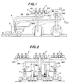
- the setting machine for transplanting plugged seedlings comprises a vehicle body 1 on which is arranged an engine 101 and the like for driving the machine along predetermined transplantation ridges in a field, and seedling taking-out device 3 supporting seedling culture trays 2 for receiving therein plugged seedlings to be planted and selectively taking the seedlings out of the seedling culture tray 2.
- the setting machine further comprises seedling transfer device 4 for forcibly transferring the taken seedlings under negative pressure to predetermined positions, and transplanting device 5 for successively transplanting the transferred seedlings along the transplantation ridges.
- the seedling culture tray 2 is formed of a foamable synthetic resin such as foaming styrol resin and separable into two parts.
- the upper part forms a tray main body 201 for accommodating culture soil, while the lower part forms a bottom body 202 adapted to be fitted with the bottom of the tray main body 201.
- the tray main body 201 is formed therein with cylindrical cells 203 arranged staggered or in a lattice.
- Each of the cells 203 includes an open top 204 and an open bottom 205 to form a through-hole in the tray main body 201 as shown in Fig. 4A.
- the shape of the cells 203 formed by the through-holes is not limited to cylindrical as shown. It may be, for example, hexagonal prismatic.
- a diameter of the cells 203 and a distance between the open tops 204 and the open bottoms 205 or a thickness of the tray main body 201 may be selected depending upon the amount of the soil received in the cells.
- the bottom body 202 forming part of the seedling culture tray 2 is formed on its bottom plate 214 with a plurality of cylindrical fitting protrusions 206 extending to close the open bottoms of the respective cells 203 of the tray main body 201 when the bottom body 202 is fitted on the tray main body 201.
- the fitting protrusions 206 are arranged staggered or in a lattice in the same fashion as the cells 203 of the tray main body 201.
- the fitting protrusions 206 are fitted in the cells 203 of the tray main body 201 and form bottoms of the cells 203 when the tray main body 201 and the bottom body 202 are fitted with each other.
- outer diameters of the fitting protrusions 206 are substantially equal to inner diameters of the open bottoms 205 of the cells 203.
- Each of the fitting protrusions 206 is formed at its top with a drain opening 207 for draining excessive culture solution supplied into the cells 203.
- each of the fitting protrusions 206 forms an inner space 208 therein having a closing top 213 spaced from the bottom plate 214.
- the inner spaces 208 serve to separate the drain openings 207 upwardly from a bottom surface 209 of the bottom body 202 to improve the efficiency in draining the excessive culture solution.
- drain openings 207 should be flush with the bottom surface 209, there could be a risk of the drain openings 207 being closed by a support base supporting the bottom body 202 so that the excessive culture solution could not be effectively drained. With the construction above described, however, the drain openings 207 are prevented from being closed by the support base so that the excessive culture solution can be drained out of the machine with high efficiency.
- Buds in the lower trays 2a grown and extending therefrom are accommodated in the spaces 208 formed in the bottom bodies 202 (Fig. 5).
- the seedling culture trays piled in the multiple stages are maintained in a germination room after seeding for three or four days until buds have grown to four or five mm. Thereafter, the seedling culture trays are transferred into a greenhouse where the trays are arranged on bases without piling so that a culture solution is uniformly sprinkled onto the buds to obtain plugged seedlings sufficiently grown. Therefore, the inner spaces 208 must be sufficiently wide enough to receive the buds. A wide range of inner spaces may of course be needed depending upon lengths of buds.
- seedling pushing-out device 220 exemplarily shown in Fig. 6 is then utilized for this purpose.
- the seedling pushing-out device 220 comprises a support base 221 for supporting a tray main body 201 and pushing-out portions 222 extending from the support base 221.
- Each of the pushing-out portions 222 requires to have a shape substantially the same as that of the open bottom 205 of the tray main body 201 and a height at least higher than that of the fitting protrusion 206 of the bottom body 202 in order to uniformly push the bottom surface of the culture soil to partially extend the seedling beyond the open top 204 of the tray main body 201.
- the roots of the seedlings can be readily separated from the cells to facilitate removal of the seedlings from the trays with ease.
- the pushing-out portions 222 uniformly push all the bottom surfaces of the culture soil so that the roots of the seedlings could not be damaged.
- the seedling taking-out device to be provided in the setting machine according to the invention will be explained hereinbelow.
- the seedling taking-out device 3 comprises a carrier base 301 for supporting the seedling culture tray 2, a seedling selecting device 302 movable in two dimensional directions below the carrier base 301 for selectively taking the seedlings out of the open bottoms 205 of the seedling culture tray 2, and transfer pipes 303 arranged between the seedling selecting device 302 and the force-transfer device 4 (Figs. 1 and 2) for transferring the seedlings taken out of the trays onto the downstream side thereof.
- the carrier base 301 is fixed to a top of a frame of the vehicle body 1 and has a plurality of openings 304 (Fig. 1) corresponding in shape and arrangement to those of the open bottoms 205 of the seedling culture tray 2 (Fig. 1).
- the openings 304 preferably have diameters somewhat larger than diameters of the open bottoms 205 of the seedling culture tray.
- the seedling selecting device 302 arranged below the carrier base 301 comprises a selecting member 305 as a support member slidable in a plane extending in parallel with the lower surface of the carrier base 301, driving unit for driving the selecting member 305 in the two dimensional directions or X direction (longitudinal direction of the seedling culture tray) and Y direction (traverse or width direction of the tray), and a support base 307 arranged below the selecting member 305 and corresponding to the carrier base 301.
- the selecting member 305 is composed of a belt extending in opposition to all the bottom surface of the tray.
- the belt is wound around a pair of drums 320A and 320B and is moved in X direction by rotation of the drums to select predetermined cells of the seedling culture tray successively.
- the selecting member 305 includes three selecting holes 308 whose intervals in the Y direction correspond to intervals of every other cell 203.
- the driving unit 306 comprises first driving device 309 for slidably driving the belt 305 as the selecting member in the X direction, and second driving device 310 for slidably driving the selecting member 305 in the Y direction.
- the second driving device 310 has two guide rods 321A and 321B extending in the Y direction and in parallel with the seedling culture tray.
- the one guide rod 321A is partially formed with screw threads to form a pair of feeding screws which serve to drive the selecting member 305 in the Y direction.
- the other guide rod 321B serves only to guide the first driving device 309 in the Y direction.
- the guide rod 321A is provided at one end with a reversible servomotor 322 fixed to the frame of the vehicle body 1.
- the other end of the guide rod 321A is rotatably mounted on the frame of the vehicle body 1. Therefore, when the servomotor is energized to be rotated predetermined rotations, the guide rod 321A is rotated so that the first driving device 309 is fed a predetermined distance in the Y direction.
- the first driving device 309 comprises a pair of feeding portions 323A threadedly engaging the feeding screws of the guide rod 321A, a pair of feeding portions 323B slidably engaging the guide rod 321B, reversible servomotors 324A and 324B fixed to the respective feeding portions 323A and 323B for feeding the belt 305 predetermined distances in the X direction, and drums 320A and 320B respectively connected to the servomotors 324A and 324B for winding the belt 305 therearound.
- the drums 320A and 320B are connected to the servomotors 324A and 324B through rotating shafts provided on the drums 320A and 320B.
- the pairs of the feeding portions 323A and 323B, the servomotors 324A and 324B and the drums 320A and 320B above described are arranged opposed on both sides of the seedling culture tray 2.
- the belt 305 to be wound around the drums 320A and 320B needs to have a width and a length sufficient to be able to move the selecting holes 308 thereof in the X direction between the ends of the seedling culture tray.
- the support base 307 is fixed to the frame of the vehicle body 1 and has a plurality of openings 314 corresponding in shape and arrangement to the openings 304 of the carrier base 301.
- the openings 314 of the support base 307 are aligned with the respective openings 304 of the carrier base 301 and permit the seedlings to pass therebetween.
- the transfer pipes 303 are connected to the underside of the support base 307.
- the transfer pipes 303 are composed of a plurality of first branch pipes 315 connected to the openings 314 of the support base 307, a funnel-shaped collecting portion 316 gathering together the branch pipes 315, a second branch pipe 317 extending downstream of the collecting portion 316, and a main pipe 318 gathering together second branch pipes 317 and extending to the seedling transfer device 4.
- the support base 307 includes the twelve openings 314 in each longitudinal row and six openings 314 in each traverse row. Therefore, if eight openings 314 (four in the longitudinal row and two in the traverse row) of the support base 307 are set in a block, the openings 314 are divided into nine blocks.
- one block includes eight first branch pipes 315 and one second branch pipe 317 collecting the eight first branch pipes 315 in the collecting portion 316 (Fig. 8).
- three second branch pipes 317 in a longitudinal row are gathered together in one main pipe 318, so that main pipes are located one in each of longitudinal rows including even and odd number of longitudinal rows.
- the number of the main pipes 318 is equal to that of the selecting holes 308 of the selecting member 305.
- This arrangement enables one of the selecting holes 308 formed in the belt 305 as the selecting member to take charge of the openings 304 in two longitudinal rows (twenty-four openings 304 in this embodiment) by sliding the belt 305 in the X and Y directions. While the above construction is only one example, it will be apparent, for example, that the support base 307 may be divided into blocks of a desired number and the number of the branch pipes may be changed depending upon the number of the blocks.
- the openings 304 of the carrier base 301 are arranged in a manner that each of them is aligned with each of the openings 314 of the support base 307, and the selecting member 305 is arranged between and slidably contacts with the carrier base 301 and the support base 307.
- the seedling culture tray 2 is suitably arranged on the carrier base 301.
- the selecting member 305 is previously positioned relative to the seedling culture tray 2 so that the selecting holes 308 of the selecting member 305 are aligned with the open bottoms at the one end of the seedling culture tray 2.
- the seedling transfer device 4 arranged downstream of the transfer pipes 303 is then actuated to cause negative pressure in the transfer pipes 303 so as to take the first seedlings out of open bottoms at the one end of the seedling culture tray.
- This seedlings pass through the selecting holes 308 and the openings 314 of the support base 307 and thereafter through the first branch pipes 315, the second branch pipes 317 and the main pipes 318 into the transplantation device 5 later described in detail.
- at least the servomotor (324B in this embodiment) arranged on the advancing side of the belt 305 is energized to be rotated a predetermined amount to unwind a predetermined length of the belt 305 from the drum 320A and at the same time to wind the same length of the belt 305 around the drum 320B in order to bring the selecting holes 308 into alignment with the next openings 304 adjacent the above openings 304 in the longitudinal direction (X direction).
- the selecting holes 308 of the belt 305 are successively moved in the X direction to the open bottoms 205 at the other end of the seedling culture tray. Thereafter, the servomotor 322 of the second driving device 310 is energized to move the selecting holes 308 of the belt 305 a predetermined distance in the Y direction by device of the first driving device 309 with the aid of its screw-thread feeding in order to bring the selecting holes 308 into alignment with the openings 304 adjacent the above openings 304 in the Y direction.
- the servomotor (324A in this embodiment) of the first driving device 309 is energized to unwind a predetermined length of the belt 305 from the drum 320B and at the same time to wind the same length of the belt around the drum 320A in order to bring the selecting holes 308 into alignment with the next openings 304 adjacent the above openings 304 in the longitudinal direction. While these operations are successively repeated, the selecting holes 308 of the belt 305 are moved to the open bottoms 205 at the one end of the seedling culture tray (on the side of the guide rod 321A). When the selecting holes 308 arrive at the open bottoms 205 at the one end of the tray, a series of the taking-out operations of the seedlings are completed.
- the belt 305 as the selecting member is not limited to the construction as above described.
- three second selecting holes 308A may be formed in the belt 305, which are also aligned in the width direction and spaced in the longitudinal direction from the first selecting holes 308. These second selecting holes 308A are positioned shifted one half of the distance between the first selecting holes 308 in the Y direction. After all the seedlings in charge of the first selecting holes 308 have been taken out, the second selecting holes 308A are to be moved by further rotations of the drums 320A and 320B to positions where seedlings in the remaining rows can be taken through the second selecting holes 308A out of the tray.
- the second selecting holes 308A are located spaced a distance more than the length of the tray from the first selecting holes 308. With this arrangement, it is possible to take all the seedlings out of the tray, while the drums 320A and 320B are continuously rotated. Therefore, the second driving device 310 can be dispensed with so that the setting machine can be more simplified in construction. Moreover, the number and the positional relationship of the selecting holes can be suitably modified depending upon the number and the arrangement of the cells of the seedling culture tray.
- a carrier base 301 as a supporting member in this embodiment is fixed to a top of a frame on a vehicle body 1 and has a plurality of openings 304 corresponding in shape and arrangement to the open bottoms 205 of the seedling culture tray 2 (Fig. 1).
- a seedling selecting device 302 arranged below the carrier base 301 is composed of a slide block as a selecting member 305 slidable relative to and in parallel with the lower surface of the carrier base 301 and driving device 306 for moving the slide block in two dimensional directions, that is to say, a longitudinal (X) direction and a width (Y) direction.
- the slide block is in the form of a rectangle formed with three selecting holes 308 extending through the slide block from its upper surface to its lower surface.
- the selecting holes 308 are arranged with intervals in the Y direction corresponding to the intervals of cells 203 of the seedling culture tray and connected to three transfer pipes 303 through flexible pipes on the lower surface side, respectively.
- the driving device 306 is composed of first driving device 309 for sliding the slide block in the X directions and second driving device 310 for sliding the slide block in the Y direction.
- the first driving device 309 comprises a pair of first guide rods 330 engaging the slide block and a first driving mechanism 331 for driving the guide rods 330 in the X direction.
- the first driving mechanism 331 comprises a pair of first rotating shafts 332A and 332B extending in the Y direction and arranged opposed to each other on both sides of the carrier base 301 and a pair of first driving belts 333 connecting together the first rotating shafts 332A and 332B and the first guide rods 330.
- the pair of the first driving belts 333 are arranged on both sides of the carrier base 301 and extend in the X direction for connecting the pulleys 334A and 334B fixed to the first rotating shafts 332A and 332B and pulleys 335A and 335B rotatably mounted at both ends of the first guide rods 330. Therefore, when the pulleys 334A and/or 334B arranged at the ends are rotated, the first driving belts 333 run to cause the first guide rods 330 to move in the X direction.
- a reversible servomotor 336 is provided at one end of any one (332A in this embodiment) of the first rotating shafts 332A and 3328, while the other end is rotatably supported in the frame of the vehicle body 1. Both ends of the other first rotating shaft 332B are rotatably mounted on the frame of the vehicle body 1.
- the first guide rods 330 extend in the Y direction through the slide block and are in sliding contact with the slide block therein. It should be noticed that the first guide rods 330 do not intersect the selecting holes 308 of the slide block.
- the first driving belts 333 are preferably cog or toothed belts and the pulleys 334A, 334B, 335A and 335B are also preferably toothed pulleys correspondingly in order to move the slide block predetermined distances by device of the servomotor 336.
- the second driving device 310 is substantially the same in construction as the first driving device.
- the second driving device 310 comprises a pair of second guide rods 340 engaging the slide block and a pair of second driving belts 343 for connecting together these guide rods 340.
- the pair of the second driving belts 343 extend in the Y direction for connecting together pulleys 344A and 344B fixed to second rotating shafts 342A and 342B and pulleys 345A and 345B rotatably mounted on both the ends of the second guide rods 340.
- the second guide rods 340 above described extend in the X direction through the slide block.
- the second guide rods 340 require to extend so as not intersect the first guide rods 330 and the selecting holes 308 of the slide block.
- the seedling culture tray 2 is arranged on the carrier base 301 so as to cause the open bottoms 205 of the tray 2 to be aligned with openings 304 of the carrier base 301, and the selecting holes 308 of the slide block are brought to be aligned with the open bottoms 205 at one end of the seedling culture tray 2.
- the seedling transfer device 4 downstream of the transfer pipes 303 is then actuated to cause negative pressure in the pipes 303 so that three seedlings above the selecting holes 308 are fed through the transfer pipes 303 into transplanting device 5 later explained in detail.
- the servomotor 336 of the first driving device 309 is actuated to move the driving belts 333 a predetermined distance so that the first guide rods 330 are moved the predetermined distance in the X direction (opposite to arrow X in Fig. 10 in this embodiment) in order to bring the selecting holes 308 into alignment with next openings adjacent in the longitudinal direction.
- new seedlings are selected to be taken out of the cells 203 and fed through the transfer pipes into the transplanting device 5. While such a controlled feeding of seedlings is repeated, the slide block is moved to the opening bottoms 205 at the other end of the seedling culture tray.
- the servomotor 346 of the second driving device 310 is energized to move the belts 343 a predetermined distance so as to move the second guide rods 340 the predetermined distance (three times the interval in the width direction between the cells of the seedling culture tray in this embodiment) in the Y direction in order to bring the selecting holes 308 into alignment with the openings 304 adjacent in the Y direction.
- the servomotor 346 of the second driving device 310 is energized to move the belts 343 a predetermined distance so as to move the second guide rods 340 the predetermined distance (three times the interval in the width direction between the cells of the seedling culture tray in this embodiment) in the Y direction in order to bring the selecting holes 308 into alignment with the openings 304 adjacent in the Y direction.
- three new seedlings adjacent in the Y direction are taken out of the cells 203 and fed into the transplanting device 5.
- the control motor 336 of the first driving device 309 is energized to be rotated in the reverse direction so as to move the slide block a predetermined distance in the X direction so that the selecting holes 308 are brought into alignment with the next openings 304 adjacent in the longitudinal direction for taking new seedlings out of the cells.
- a series of such operations are successively repeated, while the selecting holes 308 of the slide block are moved in the longitudinal direction to the open bottoms 205 at the end of the seedling culture tray.
- the seedling transfer device to be used in the setting machine according to the invention will be explained hereinafter.
- Figs. 11 and 12 illustrate the principal parts of the seedling transfer device arranged downstream of the transfer pipes 303 connected to the selecting holes 308 of the openings 314 of the support base 307 (or selecting holes 308 of the selecting member 305, as the case may be).
- the seedling transfer device is composed of a suction pump 401 driven by an engine 101 for causing negative pressure in the transfer pipe 303, a suction pipe 402 connected to the suction pump 401, and a suction portion 403 for connecting the suction pipe 402 to the transfer pipe 303.
- the suction portion 403 comprises a cylindrical surrounding member 405 for surrounding a plurality of openings 404 formed in the circumferential wall of the transfer pipe on the downstream side thereof.
- the surrounding member 405 is formed to have a shape and a size to provide a constant clearance relative to the outer circumferential surface of the transfer pipe 303 and surrounds all the openings 404.
- the transfer pipe 303 extends through the center portion of the surrounding member 405 in the axial direction and is connected to the surrounding member 405 in an airtight manner.
- One end of the suction pipe 402 is connected to the circumferential wall of the surrounding member 405 in an airtight manner.
- the transfer pipe 303 in the vertical direction in the proximity of the suction portion 403 in order to give inertia force to the seedling when it passes through the suction portion 403.
- the transfer pipe is provided at its end with a gate valve 406 so that the seedling is subjected to sufficient negative pressure by maintaining the gate valve 406 closed during the taking-out and transfer of the seedling in the transfer pipe 303.
- the taking of the seedlings out of the bottom of the seedling culture tray is accomplished by connecting the seedling transfer device 4 and the taking-out device 3 constructed as above described with the transfer pipe 303.
- the transplanting device 5 to be provided on the setting machine according to the invention will be explained herein below.
- the respective transplanting device 5 arranged in parallel are connected to downstream ends of the main pipes 318 of the transfer pipes 303.
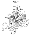
- the transplanting device 5 is composed of a transplanting mechanism 501 for transplanting seedlings fed through the transfer pipes 303 along predetermined transplantation ridges in a field, and a frame 504 having a pair of front wheels 502 and a pair of rear wheels 503 mounted thereon for guiding the transplanting mechanism 501 along the transplantation ridges in the field as shown in Figs. 14 and 15.
- the transplanting mechanism 501 is composed of planting device 520 for forming holes 54 in the ground along predetermined ridges in a field, for example, covered by mulches 510 (Fig. 17) and transferring seedlings into the holes 54, driving device 521 for driving the planting device 520 at least in vertical directions, guide device 525 for guiding the vertical movements of the planting device, and control device 522 for controlling the time when the seedlings fed through the transfer pipes 303 are supplied into the planting device 520.
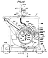
- the planting device 520 comprises an openable and closable drilling unit 523 in the form of a "bill" for forming holes 54 along transplantation ridges in the field and an actuator mechanism 524 for timely opening and closing of the drilling unit 523.
- the drilling unit 523 is composed of a first drilling member 523A and a second drilling member 523B in pair to form the bill-shaped unit and arranged under a main body 526 of the planting device 520.
- the first drilling member 523A is pivotally connected with its upper end to main body 526 so as to be rotatable about a pivot point 527.
- To the upper end of the second drilling member 523B is fixed an operating arm 528 constituting part of the actuator mechanism 524.
- the operating arm 528 extends substantially horizontally and is pivotally connected with its one end to the main body 526 to be rotatable about a pivot point 529.
- the operating arm 528 is provided at the other end with a roller 530 which co-operates with a roller guide member 531 later described constituting part of the open and close mechanism 524.
- the operating arm 528 is provided on the side of the pivot point 527 of the first drilling member 523A with an urging roller 532 which urges the first drilling member 523A upon rotation of the operating arm 528 about the pivot point 529 to rotate the first drilling member 523A about the pivot point 527.
- the first drilling member 523A is formed with a shoulder 533 positioned between the pivot point 527 and the front end of the first drilling member 523A to form a substantially horizontal operating surface in the proximity of the end of the first drilling member on the side of the pivot point 527. This operating surface is arranged closely to the underside of the urging roller 532.
- the second drilling member 523B fixed to the operating arm 528 is pivotally moved toward the side of the operating arm 528, and in conjunction therewith the the urging roller 532 of the operating arm urges the shoulder 533 of the first drilling member 523A downwardly to displace it about its pivot point 527 away from the second drilling member 523B.
- the closed drilling unit 523 is opened.
- a tension spring 534 is arranged between the first and second drilling members 532A and 532B.
- the roller guide member 531 is secured to the frame 504 to form part of the actuator mechanism (Figs. 14 and 15). As shown in detail in Fig. 16, the roller guide member 531 is arcuate and arranged within the movement range of the roller 530. In this embodiment, the roller guide member 531 is so arranged that its one end 531A is located in a position where the roller 530 of the operating arm 528 starts to engage the one end 531A of the roller guide member 531 when the planting device 520 has been moved to the lowermost position.
- the other end 531B of the roller guide member 531 is arranged at a position where the roller 530 starts to disengage from the guide member 531 when the planting device 520 has been rotated from the upper position substantially three fourths of its one rotation in a direction shown by an arrow E.
- An arcuate slide guide surface 531C is formed between the ends 531A and 531B of the roller guide member 531. Rotating angles of the operating arm 528 vary depending upon distances between engaging positions of the roller 530 with the guide surface 531C and centers of revolution orbits of the roller 530.
- the roller 530 engages the guide surface 531C at a position which is remote from the center of the revolution orbit of the roller 530 moving with the revolution of the planting device 520, the rotating angle of the operating arm 528 becomes smaller.
- the roller 530 engages the guide surface 531C at a position which is close to the center of the revolution orbit of the roller 530, the rotating angle of the operating arm 528 becomes larger. Therefore, the curvature of the roller guide member 531 needs to be determined in consideration of the above relation.
- the guide surface 531C of the guide member 531 in this embodiment is so arranged that the rotating angle of the operating arm 528 becomes the maximum value when the planting device 520 has been rotated from the uppermost position substantially one half of the revolution in the direction E so that the roller 530 has arrived at the end 531A of the guide member 531, while the operating arm 528 assumes substantially horizontal position when the planting device 520 has been rotated substantially three fourths of the revolution so that the roller 530 has arrived at the other end 531B of the guide member 531.
- the rotating angle of the operating arm 528 becomes the maximum value when the planting device 520 has been rotated from the uppermost position substantially one half of the revolution in the direction E so that the roller 530 has arrived at the end 531A of the guide member 531, while the operating arm 528 assumes substantially horizontal position when the planting device 520 has been rotated substantially three fourths of the revolution so that the roller 530 has arrived at the other end 531B of the guide member 531.
- the slide guide surface 531C of the guide member 531 is curved in a manner that the rotating angle of the operating arm 528 progressively decreases as the roller 530 moves upwardly between the ends 531A and 531B of the slide guide member 531. Therefore, the open angle of the drilling unit 523 becomes the maximum (to such extent as to enable a seedling to fall into a hole 54) when the planting device 520 has been rotated from the uppermost position shown in solid lines in Fig. 16 substantially one half of the revolution in the direction E so that the drilling unit 523 has arrived at the deepest position in the ground.
- the rotational angle of the drilling unit 532 progressively decreases and becomes 0° when the planting device 520 has arrived at the position of the three fourths rotated position and the drilling unit has raised sufficiently from the ground surface F. Under this condition, the planting device 520 is moved to the initial uppermost position to complete the transplantation of one seedling.
- Guide device 525 for causing the suitable rotation of the planting device 520 is composed of a pair of support members 540A and 540B provided on the main body 526 of the planting device, and a pair of guide discs 541A and 541B in the form of circular plates vertically fixed to the bottom surface of the frame 504 for guiding the support members 540A and 540B as shown in Fig. 14.
- the support members 540A and 540B in the form of bars are provided on the main body 526 so as to extend vertically relative to side surfaces of the guide discs 541A and 541B. Moreover, the support member 540B is arranged eccentric relative to and vertically above the support member 540A. Therefore, the support members 540A and 540B extend in parallel with and vertically spaced a predetermined distance from each other and are fixed to opposed surfaces of the main body 526 so as to be perpendicular to side surfaces of the guide discs 541A and 541B, respectively.
- the guide discs 541A and 541B are provided in parallel with the side surfaces of the frame 504 and formed with guide grooves 542A and 542B for guiding the support members 540A and 540B.
- the guide grooves 542A and 542B are annular as shown in Fig. 15.
- the center of the annular guide groove 542B is arranged eccentric to and vertically above the center of the annular guide groove 542A.
- the eccentric distance between the centers of the guide grooves 542A and 542B is coincident with the eccentric distance between the support members 540A and 540B.
- the guide grooves 542A and 542B are not limited to the annular ones as shown but may be suitably modified. For example, elliptical could be preferable as the case may be.
- the main body 526 of the planting device is caused to perform the proper rotating movement, and at the same time the bill-shaped drilling unit 523 can be maintained in the vertical direction.
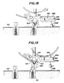
- the driving device 521 for driving the planting device 520 includes a hydraulic cylinder 543 having a piston rod whose rod end is pivotally connected to the main body 526 of the planting device.
- the head end of the cylinder is pivotally connected to the frame 504. Therefore, a reciprocal movement of the piston of the cylinder 543 causes a rocking movement of the hydraulic cylinder 543 as shown in Fig. 15.
- the piston of the hydraulic cylinder 543 is controlled in a manner that the piston continues to advance until the piston intersects the center of the guide groove 542 and thereafter the piston continues to retract until the piston again intersects the center of the guide groove 542.
- the hydraulic pressure of the hydraulic cylinder has to be controlled in such a manner that notwithstanding the advancement of the transplanting device 5, the drilling unit 523 being positioned in the ground is stationary at a predetermined position and adapted to undergo a vertical movement only in the vertical direction without moving in advancing and retracting directions relative to the ground surface (Figs. 17 to 19).
- the planting device 520 is subjected to a force in an inclined direction from the above and rearward from the hydraulic cylinder 543, the moving speed is divided into a horizontal moving speed V1 and a vertical moving speed V2.
- the control device 522 for controlling the time when the seedlings transferred in the transfer pipes are fed into the planting device 520 comprises a gate valve 544 provided in the proximity of the downstream most end of the transfer pipe 303, a hydraulic cylinder 545 for opening the gate valve 544, a compression spring 546 for closing the gage valve 544 as shown in Fig. 14.
- the gate valve 544 is composed of a movable plate which is pivotally received on a top plate 547 fixed to the upper surface of the frame 504 so as to be rotated in a horizontal plane about a pin 548.
- the gate valve 544 may be substantially the same as the gate valve 406 (Fig. 11) explained in connection with the seedling transfer device.
- the rod end of the piston rod of the hydraulic cylinder 545 fixed to the top plate 547 and hydraulically controlled is connected to a portion of the gate valve 544 on the opposite side of the pin 548 with respect to the transfer pipe 303.
- the hydraulic cylinder 545 includes a single-acting piston which is retracted into the cylinder 545 by hydraulic pressure acting upon the piston for opening the gate valve 544 and is extended in the opposite direction by the spring force of the compression spring 546 under no hydraulic pressure.
- the piston rod of the piston and the compression spring 546 are arranged in alignment with each other and one end of the spring 546 is connected to the rod end of the piston rod and the other end is fixed to the top plate 547.
- the time when the seedlings are fed into the planting device 520 can be suitably controlled.
- the gate valve in the event that a seedling is arranged in the drilling unit 523 and in the event that the drilling unit 523 is opened, the gate valve is maintained in the closed condition by device of the compression spring 546 so that the seedling fed through the transfer pipe 303 is once stopped before the planting device.
- the hydraulic pressure is applied into the hydraulic cylinder 545 to open the gate valve 544 so that the seedling is fed into the planting device.
- the actual opening and closing time of the gate valve 544 in this embodiment will be explained later.
- the main body 526 of the planting device may be provided with an additional mulch opening device 550 which is composed of a support member 551 extending forward from the main body 526 in the horizontal direction and fixed with one end to the main body, and an urging trowel 552 mounted on the front end of the support member 551.
- the support member 551 is composed of a main arm 551A having one end fixed to the main body 526 and an L-shaped branch arm 551B pivotally connected to the center portion of the main arm 551A.
- a buffer member 553 and a tension spring 554 are secured to both the arms 551A and 551B therebetween.
- the buffer member 553 is secured to the front end of the branch arm 551B for maintaining the distance between both the arms 551A and 551B constant and is so arranged as to abut against the main arm 551A in order to absorb the force acting upon the branch arm.
- the tension spring 554 serves to apply tensile force between both the arms in order to maintain the buffer member 553 abutting against the main arm 551A.
- the urging trowel 552 is cylindrical and provided at underside of the branch arm 551B (Fig. 14). Moreover, the urging trowel 552 includes therein a gas burner for keeping high temperature required to form openings 555 (Fig. 19) in the mulch 510 made of a plastic material.
- the urging trowel 552 serves to remove predetermined portions of the mulch 510 which will obstruct the transplantation of seedlings using the drilling unit. Therefore, the urging trowel 552 requires to have a function capable of forming openings 555 in the mulch at positions corresponding to the drilling unit before it is inserted into the ground along the transplantation ridges.
- the urging trowel 552 requires to have a function capable of rotating in synchronism with the rotation of the planting device 520 in order to form an opening in the mulch previously for transplanting a next seedling during transplanting a preceding seedling using the drilling unit. Accordingly, the urging trowel 552 is arranged on the underside of the branch arm 551B at the position where the bottom surface of the urging trowel is brought into contact with the surface of the mulch during the transplantation of the seedling using the drilling unit and the urging trowel is able to open the mulch openings 555 successively with intervals equal to those of the transplantation of the seedlings by the drilling unit.
- the mounted position of urging trowel 552 should be changed depending upon the moving speed of the transplanting device 5 and the rotating speed of the planting device 520. It is, therefore, preferable that the urging trowel 552 is slidable in longitudinal direction of the branch arm 551B and able to be fixed at any desired position and that the urging trowel 552 is displaceable in vertical direction relative to the branch arm and able to be fixed at any desired position.
- the underside of the branch arm 551B is formed with a plurality of internal threads with predetermined intervals, which are adapted to threadedly engage with the rod 552A of the urging iron 552, thereby enabling the urging trowel 552 to be adjusted in the horizontal directions.
- the rod 552A and the trowel main body 552B are threadedly connected with each other.
- the position of the urging trowel 552 is adjustable in vertical directions also.
- a seedling fed through the transfer pipe 303 is once stopped on the gate valve 544.
- the gate valve 544 is opened to drop the seedling into the planting device 520 when the drilling unit 523 has arrived at a position close to the uppermost position.
- the fallen seedling is fed through the through-passage formed in the main body 526 of the planting device 520 to the drilling unit 523 in the closed condition and kept in the drilling unit 523 until it has arrived at the position shown in Fig. 17. Thereafter, when the drilling unit has been moved nearly to the substantially lowermost position and sufficiently inserted into the ground as shown in Fig.
- the roller 530 of the operating arm 528 abuts against the end of the slide guide member 531 so that the operating arm 528 is raised upwardly to open the drilling unit by the lever action of the operating arm 528 as described above.
- the urging trowel 552B provided in the mulch opening device 550 forms an opening 555 in the mulch 510.
- the roller 530 moves on the slide guide surface 531C, the drilling unit 523 is maintained in the opened condition and continues to move vertically, leaving the seedling behind in the hole 54.
- the roller 530 disengages from the slide guide surface 531C to close the drilling unit.
- a new seedling is fed into the planting device as well. Thereafter, the operation described above is repeated.
- the drilling unit is fully opened when it has been moved to the lowermost position in this embodiment.
- the engaging positional relationship between the roller 530 and the slide guide member 531 may be so adjusted that while the drilling unit is being raised, it is progressively opened to arrange the seedling into the hole 54.
- Such an arrangement is preferable in the case that the soil in the field is somewhat hard.
- Mud removing device 680 is arranged below the drilling unit 523 for removing mud stuck to the drilling unit 523 as shown in Figs. 14, 20 and 21.
- the mud removing device 680 includes a support member 681 fixed in a manner bridging lower frame members of the frame 504, and a mud removing opening 682 formed in the support member 681 at its center.
- the support member 681 is in the form of a thin plate and arranged extending above the transplantation ridges.
- the mud removing opening 682 is formed elongated in the moving direction of the setting machine. Both ends 682A and 682B of the opening 682 are semicircular and located at positions where these ends contact side surfaces of the drilling unit when the drilling unit 523 is raised and lowered.
- each of the ends 682A and 682B of the opening 682 is preferably provided with mud removing elastic members 683A and 683B made of an elastic rubber.
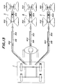
- the planting device 5 described above may be arranged independently from each other as shown in Fig. 13.
- the front and rear wheels 502 and 503 provided on the respective planting device 5 may be connected by shafts.
- elastic members for example, springs are provided at ends of the shafts and between the wheels so that the respective planting device 5 can be properly followed to corresponding transplantation ridges even if the ridges are formed as levees.
- the negative pressure always acts in the transfer pipes by actuating the seedling transfer device 4 during the transplanting operation, taken-out seedlings are always transferred in the transfer pipes from the upstream side (tray side) to the downstream side (drilling unit side). Therefore, the seedlings arranged in the seedling culture tray are taken out of the tray toward downwardly upon moving the selecting member 305 (M) of the seedling taking-out device 3 and fed through the transfer pipes 303 to the gate valve 544 (K) provided in the control device 522. At this moment, the gate valve 544 is kept in the closed condition so that the movement of the seedlings is once stopped at the position N3 of the gate valve.
- the gate valve is opened so that the seedling is fed to the position N4 in the drilling unit.
- the gate valve 544 is closed and the same time the selecting member 305 moves for the predetermined time to take a next seedling from the seedling culture tray toward downwardly. The above series of operations are then repeated until completion of successive transplantation of all the seedlings in the seedling culture tray.
- a sensor S is additionally provided as part of the control device at the gate valve position N3.
- the sensor S serves to detect whether a seedling actually exists or not at the gate valve position N3 immediately before the gate valve 544 is opened. In the case that no seedling is detected at the gate valve position N3 by device of the sensor S, the setting machine itself is stopped and rested until a seedling has been supplied. Thereafter, the setting machine is started again. It is possible to prevent plantation ridges from missing seedling or seedlings in this manner.
- a chart with the lapse of time as shown in Fig. 23 is only one example. It is possible of course to modify such a chart in various manner if required.
- the setting machine comprises a movable vehicle body which comprises a seedling taking-out device for supporting thereon seedling culture trays made of synthetic resin having a plurality of cells accommodating therein seedlings to be transplanted, and for selectively taking the seedlings out of the cells of the trays, a seedling transfer device for forcedly transferring the taken-out seedlings under negative pressure to predetermined positions, and a transplanting device for receiving the seedlings transferred in the predetermined positions and transplanting them into the ground. Therefore, the setting machine according to the invention is capable of sufficiently accommodating seedling culture trays made of synthetic resin and can positively prevent roots of seedlings from being damaged in transplanting the seedlings with the setting machine. Moreover, according to the invention, all the operations from taking-out to transplantation of seedlings can be readily and completely automatized into consistent mechanical operations, and remarkable improvement in operating efficiency and significant saving in labour can be accomplished particularly in transplanting seedlings along multiple ridges in fields.
Claims (24)
- Machine de pose qui comprend un châssis de véhicule mobile (1) comprenant :- un support de plateau de culture destiné à supporter un plateau de culture (2) à semis qui présente une pluralité de cellules (203) qui contiennent des semis à repiquer ;- un dispositif de sélection (302) pour prélever sélectivement les semis hors de cellules prédéterminées (203) dudit plateau (2) en succession sous une pression négative ;- un dispositif de transfert de semis (4) pour transférer à force les semis prélevés jusqu'à une position prédéterminée sous une pression négative, ledit dispositif de transfert (4) comprenant un tube de transfert (303) présentant une extrémité supérieure pour recevoir les semis prélevés, une extrémité inférieure, et une source de pression négative raccordée au tube de transfert à l'extrémité aval afin de transporter à force les semis le long du tube de transfert jusqu'à la position prédéterminée ; et- un appareil de repiquage (5) pour recevoir les semis transférés à la position prédéterminée et pour les repiquer dans le sol,
caractérisée en ce que- le support pour les plateaux de culture maintient stationnaire le plateau de culture (2),- le dispositif de sélection (302) comprend un élément de sélection (305) formé avec au moins un trou de sélection (308), et des moyens pour déplacer l'élément de sélection (305) par rapport au plateau de culture (2) stationnaire, dans des directions prédéterminées dans un plan qui est parallèle à une surface du fond du plateau de culture (2), afin d'amener ledit au moins un trou de sélection (308) en alignement avec des cellules prédéterminées (203) du plateau de culture (2) en succession, et- l'extrémité aval du tube de transfert (303) est décalée horizontalement par rapport à son extrémité amont. - Machine de pose selon la revendication 1, dans laquelle le support des plateaux de culture, destiné à supporter le plateau de culture (2), comprend un élément de support (base porteuse 301) formée avec des ouvertures (304) permettant que les semis prélevés hors desdites cellules du plateau de culture (2) passent à travers lesdites ouvertures et à travers les fonds ouverts (205) des cellules (203), le plateau de culture (2) comportant en tant que cellules (203) une pluralité de perçages traversants.
- Machine de pose selon la revendication 2, dans laquelle l'élément de sélection (305) comprend une courroie qui s'étend sur la totalité d'une surface de fond de l'élément de support, et les moyens pour déplacer l'élément de sélection (305) comprennent une paire de tambours (320A, 320B) pour enrouler la courroie et l'amener à se déplacer dans sa direction longitudinale, et un premier dispositif d'entraînement (309) pour entraîner les tambours (320A, 320B) dans une direction d'enroulement de la courroie, ledit au moins un trou de sélection (308) comprenant une pluralité de trous de sélection (308) formés dans la courroie et espacés les uns des autres dans la direction de la largeur, lesdits trous de sélection (308) étant adaptés à être alignés avec des cellules prédéterminées (203) du plateau de culture (2) dans la direction longitudinale de la courroie en entraînant la courroie au moyen du premier dispositif d'entraînement (309).
- Machine de pose selon la revendication 3, dans laquelle les moyens pour déplacer l'élément de sélection (305) comprennent en outre un second dispositif d'entraînement (310) afin d'entraîner lesdits tambours (320A, 320B) dans la direction de la largeur de la courroie, lesdits trous de sélection (308) étant adaptés à être alignés avec des cellules prédéterminées (203) du plateau de culture (2) dans la direction de la largeur de la courroie en entraînant la courroie au moyen du premier dispositif d'entraînement (309) et du second dispositif d'entraînement (310).
- Machine de pose selon l'une ou l'autre des revendications 2 et 3, comprenant une base de support (307) agencée de manière stationnaire en position adjacente à ladite courroie sur un côté opposé à l'élément de support du plateau de culture (2) afin de supporter ladite courroie dans une relation de contact étanche à l'air vis-à-vis de celle-ci, ladite base de support (307) étant formée avec des ouvertures (314) présentant le même agencement et le même nombre que les ouvertures (304) de l'élément de support, permettant grâce à ceci de prélever les semis hors des cellules (203) du plateau de culture (2) et de les transférer à force à travers des passages associés aux ouvertures (314) de la base de support (307) jusqu'à une position prédéterminée, lorsque chaque trou de sélection (308) de la courroie est aligné avec une ouverture (314) de la base de support (307).
- Machine de pose selon la revendication 2, dans laquelle l'élément de sélection (305) comprend un bloc coulissant agencé en position adjacente à une surface du fond dudit élément de support, et les moyens pour déplacer l'élément de sélection (305) comprennent un premier dispositif d'entraînement (309) pour déplacer le bloc coulissant dans une direction longitudinale du plateau de culture (2) et un second dispositif d'entraînement (310) pour entraîner le bloc coulissant dans la direction de la largeur du plateau de culture (2), ledit bloc coulissant étant formé avec au moins un trou de sélection (308) qui peut être aligné avec des cellules prédéterminées (203) du plateau de culture (2), en entraînant le bloc coulissant au moyen du premier dispositif d'entraînement (309) et du second dispositif d'entraînement (310).
- Machine de pose selon la revendication 6, dans laquelle ledit bloc coulissant est formé avec une pluralité de trous de sélection (308) espacés les uns des autres dans la direction longitudinale et/ou dans la direction de la largeur du plateau de culture (2).
- Machine de pose selon la revendication 6, dans laquelle la machine de pose est construite de telle manière que lesdits semis prélevés hors des cellules (203) du plateau de culture (2) sont transférés à force à la position prédéterminée à travers le trou de sélection (308) du bloc coulissant et à travers un passage raccordé à ce trou, ledit passage étant flexible dans une zone dans laquelle le passage est raccordé au bloc coulissant.
- Machine de pose selon la revendication 2, dans laquelle ledit tube de transfert (303) s'étend depuis l'élément de sélection (305) sensiblement vers le bas et horizontalement jusqu'à la position prédéterminée.
- Machine de pose selon la revendication 9, dans laquelle ledit tube de transfert (303) est flexible, au moins dans une zone de jonction avec l'élément de sélection (305).
- Machine de pose selon la revendication 9, dans laquelle ladite source de pression négative comprend une pompe de succion (401) pour produire une pression négative dans ledit tube de transfert (303), une partie de succion (403) agencée en position adjacente au tube de transfert (303) à son extrémité aval et raccordée à la pompe de succion (401), et une vanne d'arrêt (406, 544) pour ouvrir ou fermer l'extrémité aval du tube de transfert (303) sur un côté de l'appareil de repiquage (5).
- Machine de pose selon la revendication 11, dans laquelle ledit tube de transfert (303) est formé dans sa circonférence extérieure avec une pluralité d'ouvertures (404) qui sont entourées par ladite partie de succion (403).
- Machine de pose selon la revendication 12, dans laquelle lesdites ouvertures (404) sont espacées sensiblement à angles égaux dans une direction circonférentielle dans la circonférence extérieure du tube de transfert (303).
- Machine de pose selon la revendication 11, dans laquelle ledit tube de transfert (303) s'étend dans une direction verticale au moins dans une zone adjacente à ladite partie de succion (403).
- Machine de pose selon la revendication 11, comprenant en outre un appareil de commande (522) qui comprend un détecteur (S) pour détecter qu'un semis a été transféré à la position prédéterminée au moyen du dispositif de transfert de semis (4), et dans laquelle ladite vanne d'arrêt (406, 544) est adaptée à être actionnée en réponse à un signal de sortie dudit détecteur (S).
- Machine de pose selon la revendication 15, dans laquelle ladite vanne d'arrêt (406, 544) est maintenue dans sa position fermée tandis que le semis est en cours de transfert dans le tube de transfert (303), et ladite vanne d'arrêt (406, 544) est ouverte lorsque le semis est fourni depuis le tube de transfert (303) dans ledit appareil de repiquage (5) de semis.
- Machine de pose selon la revendication 1, dans laquelle ledit appareil de repiquage (5) comprend un dispositif de plantation (520) possédant une première extrémité pour recevoir un semis prélevé depuis l'extrémité aval du tube de transfert (303), et une seconde extrémité pour percer un trou dans le sol et pour planter le semis reçu depuis la première extrémité à l'intérieur du trou, un dispositif d'entraînement (521) pour entraîner ledit dispositif de plantation (520) pour provoquer son déplacement au moins en direction verticale, et un dispositif de guidage (525) pour guider ledit dispositif de plantation (520) qui est déplacé dans la direction verticale, ledit dispositif de guidage (525) maintenant la seconde extrémité du second dispositif de plantation (520) sensiblement verticalement par rapport à la surface du sol, au moins lorsque le dispositif de plantation (520) est en cours d'introduction dans le sol.
- Machine de pose selon la revendication 17, dans laquelle ledit dispositif de plantation (520) est déplacé dans une direction de recul par rapport à la machine de pose, à une vitesse égale à une vitesse d'avance de la machine de pose.
- Machine de pose selon la revendication 7, dans laquelle ladite seconde extrémité du dispositif de plantation (520) est formée sous la forme d'une unité de forage (523) en forme de bec qui est capable de subir un déplacement d'ouverture ou de fermeture, et un mécanisme d'actionnement (524) est prévu pour maintenir l'unité de forage (523) fermée lorsqu'elle est introduite dans le sol, et pour ouvrir l'unité de forage (523) lorsqu'on plante le semis.
- Machine de pose selon la revendication 17, dans laquelle ledit dispositif de guidage (525) est construit de manière à guider le dispositif de plantation (520) le long d'un trajet prédéterminé, de sorte que ladite seconde extrémité passe alternativement par une position dans laquelle la seconde extrémité pénètre dans le sol et une position dans laquelle la seconde extrémité se sépare de la surface du sol, tandis que le dispositif de plantation (520) est maintenu dans une position verticale par rapport au sol.
- Machine de pose selon la revendication 17, dans laquelle un cylindre hydraulique (543) est prévu en tant que dispositif d'entraînement (521).
- Machine de pose selon la revendication 17, dans laquelle un appareil de commande (522) est prévu, qui peut être déplacé entre une position dans laquelle un semis est fourni à la première extrémité du dispositif de plantation (520), et une position dans laquelle le semis est empêché d'être amené dans la première extrémité du dispositif de plantation (520).
- Machine de pose selon la revendication 22, dans laquelle ledit dispositif de commande (522) occupe cette position dans laquelle le semis est fourni à la première extrémité du dispositif de plantation (520) lorsque ladite seconde extrémité du dispositif de plantation (520) est dans une position espacée de la surface du sol.
- Machine de pose selon la revendication 23, dans laquelle ledit dispositif de commande (522) est actionné en synchronisme avec le mouvement de rotation des roues de déplacement de la machine de pose.
Applications Claiming Priority (11)
| Application Number | Priority Date | Filing Date | Title |
|---|---|---|---|
| JP33132588A JPH02177812A (ja) | 1988-12-29 | 1988-12-29 | 定植機 |
| JP331326/88 | 1988-12-29 | ||
| JP33132688A JPH02177823A (ja) | 1988-12-29 | 1988-12-29 | 育苗トレー |
| JP331325/88 | 1988-12-29 | ||
| JP119427/89 | 1989-01-31 | ||
| JP1942889A JPH02200108A (ja) | 1989-01-31 | 1989-01-31 | 定植機における苗抜取り装置 |
| JP1942989A JPH02200106A (ja) | 1989-01-31 | 1989-01-31 | 定植機における苗の強制輸送装置 |
| JP1942789A JPH02200107A (ja) | 1989-01-31 | 1989-01-31 | 定植機における苗移植装置 |
| JP119429/89 | 1989-01-31 | ||
| JP119428/89 | 1989-01-31 | ||
| PCT/JP1989/001338 WO1990007263A1 (fr) | 1988-12-29 | 1989-12-28 | Machine de mise en terre |
Publications (3)
| Publication Number | Publication Date |
|---|---|
| EP0457906A1 EP0457906A1 (fr) | 1991-11-27 |
| EP0457906A4 EP0457906A4 (en) | 1992-04-29 |
| EP0457906B1 true EP0457906B1 (fr) | 1995-07-19 |
Family
ID=27520132
Family Applications (1)
| Application Number | Title | Priority Date | Filing Date |
|---|---|---|---|
| EP90901004A Expired - Lifetime EP0457906B1 (fr) | 1988-12-29 | 1989-12-28 | Machine de mise en terre |
Country Status (6)
| Country | Link |
|---|---|
| US (1) | US5209170A (fr) |
| EP (1) | EP0457906B1 (fr) |
| AT (1) | ATE125105T1 (fr) |
| AU (2) | AU625646B2 (fr) |
| DE (1) | DE68923565D1 (fr) |
| WO (1) | WO1990007263A1 (fr) |
Cited By (2)
| Publication number | Priority date | Publication date | Assignee | Title |
|---|---|---|---|---|
| DE102011104902A1 (de) | 2010-06-16 | 2011-12-22 | Technische Universität Dresden | Landwirtschaftliche Maschine zum Pflanzen von Steckhölzern |
| CN103125300A (zh) * | 2013-03-12 | 2013-06-05 | 阳曲县诚同茂业科技有限公司 | 联驱互串式育苗机组 |
Families Citing this family (29)
| Publication number | Priority date | Publication date | Assignee | Title |
|---|---|---|---|---|
| US5676072A (en) * | 1992-08-10 | 1997-10-14 | Williames Hi-Tech International Pty Ltd. | Apparatus for automatically planting seedlings taken from a hard seedling tray |
| JP3673285B2 (ja) * | 1992-10-09 | 2005-07-20 | 櫻護謨株式会社 | 屋外作業自動化システム |
| US5494399A (en) * | 1993-02-19 | 1996-02-27 | Rapsco, Inc. | Can end distributor apparatus |
| US5431116A (en) * | 1993-10-26 | 1995-07-11 | New Century Technology Corporation | Pneumatic transplanter |
| JPH07194208A (ja) * | 1993-12-30 | 1995-08-01 | Yanmar Agricult Equip Co Ltd | 苗移植機の作業台構造 |
| US5445089A (en) * | 1994-07-27 | 1995-08-29 | Houng; Chong L. | Seedlings transplanting machine |
| US5765491A (en) * | 1996-09-05 | 1998-06-16 | Precision Measurements Corporation | Seedling transfer apparatus and method |
| US6142083A (en) * | 1998-02-26 | 2000-11-07 | Cox, Jr.; Arville B. | Tobacco and vegetable seeder |
| DE19845612A1 (de) * | 1998-10-05 | 2000-04-06 | Rudolf Cordes | Vorrichtung zum Setzen von Pflanzenstecklingen |
| US6615753B1 (en) * | 1999-06-22 | 2003-09-09 | Northwest Revegetation | Expandable stinger planter |
| US6158362A (en) | 1999-06-22 | 2000-12-12 | Culley; Daniel A. | Expandable stinger planter |
| US6634306B1 (en) | 2002-07-30 | 2003-10-21 | Frank W. Faulring | Method and apparatus for transplanting |
| US7607260B1 (en) * | 2002-08-15 | 2009-10-27 | Fraleigh Nursery, Llc | Method and planting bed for production of a plant in a container |
| US7036440B1 (en) | 2002-09-12 | 2006-05-02 | Gil A Sena | Adjustable tray size automatic seedling planting apparatus |
| US7363868B1 (en) | 2003-09-12 | 2008-04-29 | Gil A Sena | Adjustable tray size automatic seedling planting apparatus |
| US7954439B2 (en) * | 2007-08-04 | 2011-06-07 | The Morning Star Company | Transplanter |
| US8122838B2 (en) | 2007-08-04 | 2012-02-28 | Faulring Mechanical Devices, Inc. | Transplanter |
| WO2012121653A1 (fr) * | 2011-03-10 | 2012-09-13 | Björkemar Construction & Consulting Bcc Ab | Procédé de manipulation des plantes dans une repiqueuse, repiqueuse et unité de repiquage |
| CN103392426B (zh) * | 2013-07-05 | 2015-05-06 | 重庆博沃发动机配件制造有限公司 | 小型插秧机拖板 |
| CN103314685A (zh) * | 2013-07-05 | 2013-09-25 | 重庆博沃发动机配件制造有限公司 | 小型插秧机拖板 |
| CN104285567B (zh) * | 2014-09-19 | 2016-06-22 | 济南高瑞生物科技有限公司 | 一种机械手自动移苗机构 |
| SE539151C2 (en) | 2014-10-24 | 2017-04-18 | Bracke Forest Ab | Device and method for transplanting plants |
| IT201600112250A1 (it) * | 2016-11-08 | 2018-05-08 | Ferrari Costruzioni Mecc S R L | Macchina trapiantatrice di piantine radicate in zolle |
| EP3547816B1 (fr) * | 2016-11-29 | 2023-07-19 | Tigercat Industries Inc. | Appareil de plantation de plants d'arbres |
| CN107646265B (zh) * | 2017-11-16 | 2023-05-23 | 山东农业大学 | 取投苗装置及吊杯式移栽机自动取苗投苗平台 |
| CN109511335A (zh) * | 2018-12-03 | 2019-03-26 | 李佳奇 | 气动化全自动插值结构 |
| CN109496506B (zh) * | 2018-12-03 | 2021-12-14 | 重庆市神女药业股份有限公司 | 一种新能源插秧机用自动插植装置 |
| US11445657B2 (en) | 2019-07-15 | 2022-09-20 | Deere & Company | Sapling planting apparatus |
| CN116941497B (zh) * | 2023-09-15 | 2024-04-12 | 易森未来(北京)机器人技术有限公司 | 一种树苗种植装置和植树机器人 |
Family Cites Families (17)
| Publication number | Priority date | Publication date | Assignee | Title |
|---|---|---|---|---|
| US3446164A (en) * | 1967-02-20 | 1969-05-27 | Barney K Huang | Automatic transplanter |
| US3712252A (en) * | 1970-11-06 | 1973-01-23 | Research Corp | Seedling growing and handling device |
| US3872805A (en) * | 1972-01-18 | 1975-03-25 | Howard A Kolk | Planting machine |
| SE378167B (fr) * | 1973-11-29 | 1975-08-25 | Mo Och Domsjoe Ab | |
| SE404646B (sv) * | 1975-04-29 | 1978-10-23 | Mo Och Domsjoe Ab | Planteringsmaskin |
| US4003530A (en) * | 1975-08-13 | 1977-01-18 | Davis Orin H | Pneumatic courier discharge unit |
| US4130072A (en) * | 1977-02-25 | 1978-12-19 | Gravi-Mechanics Co. | Field transplant systems and methods and components thereof |
| FR2432265A1 (fr) * | 1978-08-02 | 1980-02-29 | Mametora Agricult Mach | Machine a repiquer de jeunes plants |
| JPS6040084Y2 (ja) * | 1979-06-29 | 1985-12-02 | 株式会社クボタ | 移植装置 |
| US4294179A (en) * | 1979-08-01 | 1981-10-13 | Bud Antle, Inc. | Dibble tube soil plug planter |
| US4341333A (en) * | 1979-08-03 | 1982-07-27 | National Research Development Corporation | Block handling apparatus |
| US4440101A (en) * | 1979-12-18 | 1984-04-03 | Illinois Tool Works Inc. | Plant transfer mechanism |
| FR2560482B1 (fr) * | 1984-03-05 | 1987-08-07 | Regero Sa | Machine notamment pour la plantation automatique des plants maraichers et horticoles |
| SE453147B (sv) * | 1986-05-06 | 1988-01-18 | Osa Ab | Forfarande och aggregat for mekaniserad settning av plantor, i synnerhet tredplantor |
| SU1463664A1 (ru) * | 1987-06-17 | 1989-03-07 | Научно-Производственное Объединение По Животноводческим Машинам "Внииживмаш" | Установка дл пневматического транспортировани сыпучего материала |
| US4843983A (en) * | 1988-02-02 | 1989-07-04 | Deere & Company | Pneumatic manifold quick coupling |
| NL8900227A (nl) * | 1988-07-07 | 1990-02-01 | Adrianus Franciscus Maria Flat | Werkwijze en inrichting voor het behandelen van planten. |
-
1989
- 1989-12-28 US US07/691,030 patent/US5209170A/en not_active Expired - Fee Related
- 1989-12-28 AU AU48307/90A patent/AU625646B2/en not_active Ceased
- 1989-12-28 AT AT90901004T patent/ATE125105T1/de not_active IP Right Cessation
- 1989-12-28 EP EP90901004A patent/EP0457906B1/fr not_active Expired - Lifetime
- 1989-12-28 DE DE68923565T patent/DE68923565D1/de not_active Expired - Lifetime
- 1989-12-28 WO PCT/JP1989/001338 patent/WO1990007263A1/fr active IP Right Grant
-
1992
- 1992-10-02 AU AU26157/92A patent/AU2615792A/en not_active Abandoned
Cited By (3)
| Publication number | Priority date | Publication date | Assignee | Title |
|---|---|---|---|---|
| DE102011104902A1 (de) | 2010-06-16 | 2011-12-22 | Technische Universität Dresden | Landwirtschaftliche Maschine zum Pflanzen von Steckhölzern |
| CN103125300A (zh) * | 2013-03-12 | 2013-06-05 | 阳曲县诚同茂业科技有限公司 | 联驱互串式育苗机组 |
| CN103125300B (zh) * | 2013-03-12 | 2014-04-02 | 阳曲县诚同茂业科技有限公司 | 联驱互串式育苗机组 |
Also Published As
| Publication number | Publication date |
|---|---|
| AU4830790A (en) | 1990-08-01 |
| WO1990007263A1 (fr) | 1990-07-12 |
| DE68923565D1 (de) | 1995-08-24 |
| AU625646B2 (en) | 1992-07-16 |
| EP0457906A1 (fr) | 1991-11-27 |
| EP0457906A4 (en) | 1992-04-29 |
| AU2615792A (en) | 1992-12-03 |
| ATE125105T1 (de) | 1995-08-15 |
| US5209170A (en) | 1993-05-11 |
Similar Documents
| Publication | Publication Date | Title |
|---|---|---|
| EP0457906B1 (fr) | Machine de mise en terre | |
| EP0653907B1 (fr) | Appareil pour planter automatiquement des semis preleves d'un bac a semis rigide | |
| US5911631A (en) | Seedling transplanter with easily detachable gripper | |
| US4947579A (en) | Computer operated automatic seedling plant transplanting machine | |
| US5596938A (en) | Apparatus for unloading seedlings from a tray and transporting them elsewhere | |
| WO1987004585A1 (fr) | Machine a planter des jeunes plants | |
| Suggs et al. | Self-feeding transplanter for tobacco and vegetable crops | |
| JPH0458809A (ja) | 苗植え付け装置 | |
| JP2815710B2 (ja) | 整列苗の分離装置 | |
| JP2892480B2 (ja) | 整列苗群の分離装置 | |
| JPH0547163B2 (fr) | ||
| JPH02200107A (ja) | 定植機における苗移植装置 | |
| JP3275244B2 (ja) | 仮植装置 | |
| JPH02200108A (ja) | 定植機における苗抜取り装置 | |
| JPH0551249B2 (fr) | ||
| JPH0547164B2 (fr) | ||
| JP2023005207A (ja) | 移植機 | |
| EP0611518A1 (fr) | Systeme pour separer des semis alignes | |
| JPH0824452B2 (ja) | 整列苗群の分離装置 | |
| JP3514343B2 (ja) | 苗移植機 | |
| CN115708435A (zh) | 甘薯自动栽苗机 | |
| JPH0541913A (ja) | 多条移植機 | |
| JP4725292B2 (ja) | 苗挿し機 | |
| JPH02286014A (ja) | 苗の自動植え替え装置 | |
| JPH08256537A (ja) | 多条移植機 |
Legal Events
| Date | Code | Title | Description |
|---|---|---|---|
| PUAI | Public reference made under article 153(3) epc to a published international application that has entered the european phase |
Free format text: ORIGINAL CODE: 0009012 |
|
| 17P | Request for examination filed |
Effective date: 19910704 |
|
| AK | Designated contracting states |
Kind code of ref document: A1 Designated state(s): AT BE CH DE ES FR GB IT LI LU NL SE |
|
| A4 | Supplementary search report drawn up and despatched |
Effective date: 19920306 |
|
| AK | Designated contracting states |
Kind code of ref document: A4 Designated state(s): AT BE CH DE ES FR GB IT LI LU NL SE |
|
| 17Q | First examination report despatched |
Effective date: 19930429 |
|
| GRAA | (expected) grant |
Free format text: ORIGINAL CODE: 0009210 |
|
| AK | Designated contracting states |
Kind code of ref document: B1 Designated state(s): AT BE CH DE ES FR GB IT LI LU NL SE |
|
| PG25 | Lapsed in a contracting state [announced via postgrant information from national office to epo] |
Ref country code: CH Effective date: 19950719 Ref country code: IT Free format text: LAPSE BECAUSE OF FAILURE TO SUBMIT A TRANSLATION OF THE DESCRIPTION OR TO PAY THE FEE WITHIN THE PRE;WARNING: LAPSES OF ITALIAN PATENTS WITH EFFECTIVE DATE BEFORE 2007 MAY HAVE OCCURRED AT ANY TIME BEFORE 2007. THE CORRECT EFFECTIVE DATE MAY BE DIFFERENT FROM THE ONE RECORDED.SCRIBED TIME-LIMIT Effective date: 19950719 Ref country code: AT Effective date: 19950719 Ref country code: BE Effective date: 19950719 Ref country code: LI Effective date: 19950719 Ref country code: ES Free format text: THE PATENT HAS BEEN ANNULLED BY A DECISION OF A NATIONAL AUTHORITY Effective date: 19950719 Ref country code: NL Free format text: LAPSE BECAUSE OF NON-PAYMENT OF DUE FEES Effective date: 19950719 |
|
| REF | Corresponds to: |
Ref document number: 125105 Country of ref document: AT Date of ref document: 19950815 Kind code of ref document: T |
|
| REF | Corresponds to: |
Ref document number: 68923565 Country of ref document: DE Date of ref document: 19950824 |
|
| PG25 | Lapsed in a contracting state [announced via postgrant information from national office to epo] |
Ref country code: SE Effective date: 19951019 |
|
| PG25 | Lapsed in a contracting state [announced via postgrant information from national office to epo] |
Ref country code: DE Effective date: 19951020 |
|
| ET | Fr: translation filed | ||
| PGFP | Annual fee paid to national office [announced via postgrant information from national office to epo] |
Ref country code: FR Payment date: 19951128 Year of fee payment: 7 |
|
| PG25 | Lapsed in a contracting state [announced via postgrant information from national office to epo] |
Ref country code: GB Effective date: 19951228 |
|
| PG25 | Lapsed in a contracting state [announced via postgrant information from national office to epo] |
Ref country code: LU Free format text: LAPSE BECAUSE OF NON-PAYMENT OF DUE FEES Effective date: 19951231 |
|
| NLV1 | Nl: lapsed or annulled due to failure to fulfill the requirements of art. 29p and 29m of the patents act | ||
| PLBE | No opposition filed within time limit |
Free format text: ORIGINAL CODE: 0009261 |
|
| STAA | Information on the status of an ep patent application or granted ep patent |
Free format text: STATUS: NO OPPOSITION FILED WITHIN TIME LIMIT |
|
| 26N | No opposition filed | ||
| GBPC | Gb: european patent ceased through non-payment of renewal fee |
Effective date: 19951228 |
|
| PG25 | Lapsed in a contracting state [announced via postgrant information from national office to epo] |
Ref country code: FR Effective date: 19970829 |
|
| REG | Reference to a national code |
Ref country code: FR Ref legal event code: ST |