EP0457906B1 - Setting machine - Google Patents
Setting machine Download PDFInfo
- Publication number
- EP0457906B1 EP0457906B1 EP90901004A EP90901004A EP0457906B1 EP 0457906 B1 EP0457906 B1 EP 0457906B1 EP 90901004 A EP90901004 A EP 90901004A EP 90901004 A EP90901004 A EP 90901004A EP 0457906 B1 EP0457906 B1 EP 0457906B1
- Authority
- EP
- European Patent Office
- Prior art keywords
- seedling
- setting machine
- seedlings
- set forth
- selecting
- Prior art date
- Legal status (The legal status is an assumption and is not a legal conclusion. Google has not performed a legal analysis and makes no representation as to the accuracy of the status listed.)
- Expired - Lifetime
Links
Images


Classifications
-
- A—HUMAN NECESSITIES
- A01—AGRICULTURE; FORESTRY; ANIMAL HUSBANDRY; HUNTING; TRAPPING; FISHING
- A01C—PLANTING; SOWING; FERTILISING
- A01C11/00—Transplanting machines
- A01C11/02—Transplanting machines for seedlings
- A01C11/025—Transplanting machines using seedling trays; Devices for removing the seedlings from the trays
Abstract
Description
- This invention relates to a setting machine as defined in the preamble of appended claim 1. The invention particularly relates to a setting machine for transplanting plugged seedlings of vegetables along predetermined transplantation ridges in fields.
- Recently, seedlings of vegetables have been cultivated by producers as a specialized profession separate from usual farmers. As a result, so-called "plugged seedlings" are supplied by the cultivators of seedlings to farmers who work exclusively to plant the supplied plugged seedlings in fields. Such a division of labour has been widely spread. Moreover, farmers in some areas often carry out mechanical planting by setting machines in order to save labour in planting plugged seedlings.
- Semi-automatic setting machines are well known. It is, however, desirable to have fully-automatic setting machines in order to improve the operation efficiency and to cut down labour costs.
- US-A-3 446 164 discloses a setting machine according to the preamble of claim 1. This setting machine has a selecting device wherein a seedling culture tray containing the seedlings to be transplanted is moved relative to the selecting device. In order to selectively remove seedlings from predetermined cells of said tray a substantial surface area is thus required on a support member to permit a two-dimensional indexing movement of the seedling culture tray. Following removal of a seedling from the seedling culture tray, the seedling is transferred to the ground by dropping through a drop tube. To accelerate the fall of a seedling through the drop tube negative pressure may be used. With this setting machine it is not possible to effect a simultaneous transplantation of seedlings to a number of ridges being laterally offset with regard to the cells from which the seedlings are removed.
- FR-A-2 560 482 discloses an automatic setting machine comprising a device for automatically transferring seedlings received in cells of a seedling culture tray. The tray containing said seedlings is supported on a table which is capable to perform movements in X- and Y-directions. By performing these two-dimensional movements seedlings are positioned beneath fingers associated with a pair of gripping pliers. These fingers are used to grip and transport the seedlings to the entry-end of a conveying tube intended to further transport the seedlings.
- Another automatic setting machine has been proposed in connection with a rice transplanter mechanism. This setting machine includes a support base for supporting seedling culture trays, and a mechanism for pulling seedlings out of the trays on the support base by transplantation pawls to transplant them into the field. This system is realized by the use of seedling culture trays made of paper materials, which are composed of pieces of cardboard arranged in lattice to form a plurality of cells. In this case, after the seedling in each cell has been pulled and separated from the tray by transplantation pawls together with cardboard pieces defining the cell, the seedling is inserted into the ground to be transplanted. However, as the prior art setting machine uses the trays made of paper material, adjacent seedlings often grow whose roots entangle with each other across walls of the cells. As a result, when the seedlings are separated from the paper tray pieces by the transplantation pawls, roots of the seedlings are often torn off or damaged, permitting viruses to invade the roots. Moreover, there is a risk that growth of the roots of the seedlings is detrimentally affected by the cardboard pieces set in the ground together with the seedlings.
- Seedling culture trays made of synthetic resins have been known, including independent cells to prevent roots of adjacent seedlings from entangling with each other. However, such seedling culture trays have been used only in completely manual operation or semiautomatic operation. In more detail, different from the paper trays, the cells of the trays made of synthetic resin could not be separated from the trays by pulling them by means of the transplantation pawls. Therefore, it has been considered that completely mechanical transplanting operation with synthetic resin trays is practically impossible or very difficult.
- It is an object of the invention to provide a setting machine which eliminates disadvantages of the prior art described above and is completely automatized with a series of mechanical operations in an easy manner utilizing seedling culture trays made of a synthetic resin.
- This invention resides in the novel discovery that a complete mechanical planting operation can be accomplished with seedling culture trays made of synthetic resin by taking seedlings out of cells of the trays with the aid of action of negative pressure, instead of separation of the seedlings from cells of trays with transplantation pawls.
- To this end the setting machine according to the present invention, which includes a seedling culture tray support, a selecting device, a seedling transfer device, and a transplanting device is characterized in that the seedling culture tray support holds the seedling culture tray stationary, the selecting device comprises a selecting member formed with at least on selecting hole and means for moving the selecting member relative to the stationary seedling culture tray in predetermined directions in a plane which is parallel with a bottom surface of the seedling culture tray to bring the at least one selecting hole into alignment with predetermined cells of the seedling culture tray successively, and in that the downstream end of the transfer pipe is horizontally offset with respect to its upstream end.
- With the above-mentioned construction of the setting machine according to the invention, seedlings are selectively taken out of cells of the seedling culture tray arranged on the vehicle body by the action of negative pressure and transferred to the transplanting means by the seedling transfer device and the transferred seedlings are transplanted into the ground by the transplanting device. Therefore, all the required operations can be carried out completely mechanically.
-
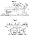
- Fig. 1 is a side view illustrating the setting machine;
- Fig. 2 is a front elevation illustrating the setting machine;
- Figs. 3A and 3B are perspective views illustrating a tray main body and a bottom body of one embodiment of the seedling culture tray, respectively;
- Fig. 4A is a sectional view taken along the line A-A in Fig. 3A;
- Fig. 4B is a sectional view taken along the line B-B in Fig. 3B;
- Fig. 5 is an enlarged sectional view of principal parts illustrating piled seedling culture trays;
- Fig. 6 is a sectional view illustrating a situation of seedlings preliminarily pushed out of the tray main body;
- Fig. 7 is a perspective view illustrating one embodiment of the seedling taking-out device of the setting machine;
- Fig. 8 is a perspective view illustrating the upstream end of the transfer pipe of the setting machine;
- Fig. 9 is a perspective view illustrating a modification of the selecting device illustrated in Fig. 7;
- Fig. 10 is a perspective view illustrating another embodiment of the seedling taking-out device of the setting machine;
- Fig. 11 is a perspective view illustrating the outline of the seedling transfer device of the setting machine;
- Fig. 12 is a sectional view illustrating principal parts of the seedling transfer device;
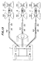
- Fig. 13 is a plan view illustrating a whole arrangement of the seedling transfer device;
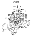
- Fig. 14 is a perspective view illustrating transplanting device to be used in setting seedlings;
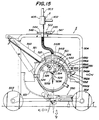
- Fig. 15 is a side view of the transplanting device shown in Fig. 14;
- Fig. 16 is an explanatory view illustrating a construction of planting device provided in the transplanting device;
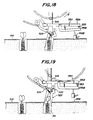
- Figs. 17-19 are explanatory views of operations of the drilling unit provided in the planting device;
- Fig. 20 is a plan view of mud removing device provided in the transplanting device;
- Fig. 21 is a sectional view taken along the line C-C in Fig. 20;
- Fig. 22 is an explanatory view schematically illustrating principal parts of the setting machine; and
- Fig. 23 is a time chart illustrating moving states of seedlings in the setting machine.
- Some preferred embodiments of the setting machine according to the invention will be explained in detail with reference to the drawings hereinafter.
- Referring to Figs. 1 and 2, the setting machine for transplanting plugged seedlings according to the invention comprises a vehicle body 1 on which is arranged an
engine 101 and the like for driving the machine along predetermined transplantation ridges in a field, and seedling taking-outdevice 3 supportingseedling culture trays 2 for receiving therein plugged seedlings to be planted and selectively taking the seedlings out of theseedling culture tray 2. The setting machine further comprisesseedling transfer device 4 for forcibly transferring the taken seedlings under negative pressure to predetermined positions, and transplantingdevice 5 for successively transplanting the transferred seedlings along the transplantation ridges. With such a construction of the setting machine, the transplantation of seedlings can be completely automatized in the mode later described. As the trays made of a synthetic resin are essential for the setting machine according to the invention, first the concrete construction of the seedling culture trays will be explained. - As shown in Figs. 3A and 3B, the
seedling culture tray 2 is formed of a foamable synthetic resin such as foaming styrol resin and separable into two parts. The upper part forms a traymain body 201 for accommodating culture soil, while the lower part forms abottom body 202 adapted to be fitted with the bottom of the traymain body 201. - The tray
main body 201 is formed therein withcylindrical cells 203 arranged staggered or in a lattice. Each of thecells 203 includes anopen top 204 and anopen bottom 205 to form a through-hole in the traymain body 201 as shown in Fig. 4A. The shape of thecells 203 formed by the through-holes is not limited to cylindrical as shown. It may be, for example, hexagonal prismatic. A diameter of thecells 203 and a distance between theopen tops 204 and theopen bottoms 205 or a thickness of the traymain body 201 may be selected depending upon the amount of the soil received in the cells. - As shown in Fig. 3B, the
bottom body 202 forming part of theseedling culture tray 2 is formed on itsbottom plate 214 with a plurality of cylindricalfitting protrusions 206 extending to close the open bottoms of therespective cells 203 of the traymain body 201 when thebottom body 202 is fitted on the traymain body 201. Thefitting protrusions 206 are arranged staggered or in a lattice in the same fashion as thecells 203 of the traymain body 201. Thefitting protrusions 206 are fitted in thecells 203 of the traymain body 201 and form bottoms of thecells 203 when the traymain body 201 and thebottom body 202 are fitted with each other. Therefore, outer diameters of thefitting protrusions 206 are substantially equal to inner diameters of theopen bottoms 205 of thecells 203. Each of thefitting protrusions 206 is formed at its top with adrain opening 207 for draining excessive culture solution supplied into thecells 203. As shown in Fig. 4B, moreover, each of thefitting protrusions 206 forms aninner space 208 therein having a closing top 213 spaced from thebottom plate 214. Theinner spaces 208 serve to separate thedrain openings 207 upwardly from abottom surface 209 of thebottom body 202 to improve the efficiency in draining the excessive culture solution. - In more detail, if the
drain openings 207 should be flush with thebottom surface 209, there could be a risk of thedrain openings 207 being closed by a support base supporting thebottom body 202 so that the excessive culture solution could not be effectively drained. With the construction above described, however, thedrain openings 207 are prevented from being closed by the support base so that the excessive culture solution can be drained out of the machine with high efficiency. - The connected state of the tray
main body 201 and thebottom body 202 above described will be explained. As shown in Fig. 5, when thefitting protrusions 206 of thebottom body 202 are inserted and fitted in theopen bottoms 205 of thecells 203 of the traymain body 201, cylindrical culturesoil receiving spaces 212 are formed by the cooperation of thecells 203 with the tops of thefitting protrusions 206. A predetermined amount of culture soil and seeds are supplied into the culturesoil receiving spaces 212 and a predetermined amount of culture solution is sprinkled thereover from above to cultivate seedlings. In this case, theseedling culture trays 2 can be piled in multiple stages for cultivating buds of the seedlings with the aid of thebottom bodies 202 shown in Fig. 4B. Buds in thelower trays 2a grown and extending therefrom are accommodated in thespaces 208 formed in the bottom bodies 202 (Fig. 5). The seedling culture trays piled in the multiple stages are maintained in a germination room after seeding for three or four days until buds have grown to four or five mm. Thereafter, the seedling culture trays are transferred into a greenhouse where the trays are arranged on bases without piling so that a culture solution is uniformly sprinkled onto the buds to obtain plugged seedlings sufficiently grown. Therefore, theinner spaces 208 must be sufficiently wide enough to receive the buds. A wide range of inner spaces may of course be needed depending upon lengths of buds. - A method of taking seedlings out of the
seedling culture trays 2 above described will be explained hereinafter. Upon completion of growth of seedlings in the trays, the seedlings are transplanted into a field. It is therefore desired to be able to take the seedlings out of the trays with ease. Seedling pushing-outdevice 220 exemplarily shown in Fig. 6 is then utilized for this purpose. The seedling pushing-outdevice 220 comprises asupport base 221 for supporting a traymain body 201 and pushing-outportions 222 extending from thesupport base 221. Each of the pushing-outportions 222 requires to have a shape substantially the same as that of theopen bottom 205 of the traymain body 201 and a height at least higher than that of thefitting protrusion 206 of thebottom body 202 in order to uniformly push the bottom surface of the culture soil to partially extend the seedling beyond theopen top 204 of the traymain body 201. By forcing the pushing-outdevice 220 with the pushing-outportions 222 constructed as above described into theopen bottoms 205 of the traymain body 201, the seedlings can be pushed upward out of the traymain body 201. In general, roots of seedlings attached to walls ofcells 203 of the trays make it difficult to take the seedlings out of the trays. By the use of the above seedling pushing-outdevice 220, the roots of the seedlings can be readily separated from the cells to facilitate removal of the seedlings from the trays with ease. In this case, the pushing-outportions 222 uniformly push all the bottom surfaces of the culture soil so that the roots of the seedlings could not be damaged. - With the seedling pushing-out
device 220 constructed as above described and arranged on the setting machine according to the invention (Fig. 2), roots of seedlings can be previously separated from the walls of the seedling culture trays before using them in combination with the setting machine, thereby greatly improving the efficiency of the setting operation. - The seedling taking-out device to be provided in the setting machine according to the invention will be explained hereinbelow.
- As shown in Fig. 7, the seedling taking-out
device 3 comprises acarrier base 301 for supporting theseedling culture tray 2, aseedling selecting device 302 movable in two dimensional directions below thecarrier base 301 for selectively taking the seedlings out of theopen bottoms 205 of theseedling culture tray 2, and transferpipes 303 arranged between theseedling selecting device 302 and the force-transfer device 4 (Figs. 1 and 2) for transferring the seedlings taken out of the trays onto the downstream side thereof. - The
carrier base 301 is fixed to a top of a frame of the vehicle body 1 and has a plurality of openings 304 (Fig. 1) corresponding in shape and arrangement to those of theopen bottoms 205 of the seedling culture tray 2 (Fig. 1). Theopenings 304 preferably have diameters somewhat larger than diameters of theopen bottoms 205 of the seedling culture tray. - The
seedling selecting device 302 arranged below thecarrier base 301 comprises a selectingmember 305 as a support member slidable in a plane extending in parallel with the lower surface of thecarrier base 301, driving unit for driving the selectingmember 305 in the two dimensional directions or X direction (longitudinal direction of the seedling culture tray) and Y direction (traverse or width direction of the tray), and asupport base 307 arranged below the selectingmember 305 and corresponding to thecarrier base 301. - The selecting
member 305 is composed of a belt extending in opposition to all the bottom surface of the tray. The belt is wound around a pair ofdrums member 305 includes three selectingholes 308 whose intervals in the Y direction correspond to intervals of everyother cell 203. - The driving
unit 306 comprisesfirst driving device 309 for slidably driving thebelt 305 as the selecting member in the X direction, andsecond driving device 310 for slidably driving the selectingmember 305 in the Y direction. Thesecond driving device 310 has twoguide rods guide rod 321A is partially formed with screw threads to form a pair of feeding screws which serve to drive the selectingmember 305 in the Y direction. Theother guide rod 321B serves only to guide thefirst driving device 309 in the Y direction. Theguide rod 321A is provided at one end with areversible servomotor 322 fixed to the frame of the vehicle body 1. The other end of theguide rod 321A, in turn, is rotatably mounted on the frame of the vehicle body 1. Therefore, when the servomotor is energized to be rotated predetermined rotations, theguide rod 321A is rotated so that thefirst driving device 309 is fed a predetermined distance in the Y direction. - The
first driving device 309 comprises a pair of feedingportions 323A threadedly engaging the feeding screws of theguide rod 321A, a pair of feedingportions 323B slidably engaging theguide rod 321B,reversible servomotors 324A and 324B fixed to therespective feeding portions belt 305 predetermined distances in the X direction, anddrums servomotors 324A and 324B for winding thebelt 305 therearound. Thedrums servomotors 324A and 324B through rotating shafts provided on thedrums feeding portions servomotors 324A and 324B and thedrums seedling culture tray 2. With such an arrangement of the first and second driving device, thebelt 305 to be wound around thedrums holes 308 thereof in the X direction between the ends of the seedling culture tray. - The
support base 307 is fixed to the frame of the vehicle body 1 and has a plurality ofopenings 314 corresponding in shape and arrangement to theopenings 304 of thecarrier base 301. Theopenings 314 of thesupport base 307 are aligned with therespective openings 304 of thecarrier base 301 and permit the seedlings to pass therebetween. As shown on Fig. 8, thetransfer pipes 303 are connected to the underside of thesupport base 307. Thetransfer pipes 303 are composed of a plurality offirst branch pipes 315 connected to theopenings 314 of thesupport base 307, a funnel-shapedcollecting portion 316 gathering together thebranch pipes 315, asecond branch pipe 317 extending downstream of the collectingportion 316, and amain pipe 318 gathering togethersecond branch pipes 317 and extending to theseedling transfer device 4. - In this embodiment, the
support base 307 includes the twelveopenings 314 in each longitudinal row and sixopenings 314 in each traverse row. Therefore, if eight openings 314 (four in the longitudinal row and two in the traverse row) of thesupport base 307 are set in a block, theopenings 314 are divided into nine blocks. In other words, one block includes eightfirst branch pipes 315 and onesecond branch pipe 317 collecting the eightfirst branch pipes 315 in the collecting portion 316 (Fig. 8). With the nine blocks each constructed above described in this embodiment, threesecond branch pipes 317 in a longitudinal row are gathered together in onemain pipe 318, so that main pipes are located one in each of longitudinal rows including even and odd number of longitudinal rows. In this case, the number of themain pipes 318 is equal to that of the selectingholes 308 of the selectingmember 305. This arrangement enables one of the selectingholes 308 formed in thebelt 305 as the selecting member to take charge of theopenings 304 in two longitudinal rows (twenty-fouropenings 304 in this embodiment) by sliding thebelt 305 in the X and Y directions. While the above construction is only one example, it will be apparent, for example, that thesupport base 307 may be divided into blocks of a desired number and the number of the branch pipes may be changed depending upon the number of the blocks. - In the seedling taking-out
device 3 according to this embodiment, theopenings 304 of thecarrier base 301 are arranged in a manner that each of them is aligned with each of theopenings 314 of thesupport base 307, and the selectingmember 305 is arranged between and slidably contacts with thecarrier base 301 and thesupport base 307. - The operation of the seedling taking-out device constructed as described above will be explained hereinafter. First, the
seedling culture tray 2 is suitably arranged on thecarrier base 301. In this case, the selectingmember 305 is previously positioned relative to theseedling culture tray 2 so that the selectingholes 308 of the selectingmember 305 are aligned with the open bottoms at the one end of theseedling culture tray 2. Theseedling transfer device 4 arranged downstream of thetransfer pipes 303 is then actuated to cause negative pressure in thetransfer pipes 303 so as to take the first seedlings out of open bottoms at the one end of the seedling culture tray. This seedlings pass through the selectingholes 308 and theopenings 314 of thesupport base 307 and thereafter through thefirst branch pipes 315, thesecond branch pipes 317 and themain pipes 318 into thetransplantation device 5 later described in detail. After the taking-out of the seedlings from the tray, at least the servomotor (324B in this embodiment) arranged on the advancing side of thebelt 305 is energized to be rotated a predetermined amount to unwind a predetermined length of thebelt 305 from thedrum 320A and at the same time to wind the same length of thebelt 305 around thedrum 320B in order to bring the selectingholes 308 into alignment with thenext openings 304 adjacent theabove openings 304 in the longitudinal direction (X direction). As a result of this, new seedlings are taken out of thecells 203 and fed through thetransfer pipes 303 into thetransplanting device 5. While such an operation is repeated, the selectingholes 308 of thebelt 305 are successively moved in the X direction to theopen bottoms 205 at the other end of the seedling culture tray. Thereafter, theservomotor 322 of thesecond driving device 310 is energized to move the selectingholes 308 of the belt 305 a predetermined distance in the Y direction by device of thefirst driving device 309 with the aid of its screw-thread feeding in order to bring the selectingholes 308 into alignment with theopenings 304 adjacent theabove openings 304 in the Y direction. As a result of this, new seedlings adjacent to the already taken out seedlings in the Y direction are selected and taken out of thecells 203. After the new seedlings have been fed, the servomotor (324A in this embodiment) of thefirst driving device 309 is energized to unwind a predetermined length of thebelt 305 from thedrum 320B and at the same time to wind the same length of the belt around thedrum 320A in order to bring the selectingholes 308 into alignment with thenext openings 304 adjacent theabove openings 304 in the longitudinal direction. While these operations are successively repeated, the selectingholes 308 of thebelt 305 are moved to theopen bottoms 205 at the one end of the seedling culture tray (on the side of theguide rod 321A). When the selectingholes 308 arrive at theopen bottoms 205 at the one end of the tray, a series of the taking-out operations of the seedlings are completed. - The
belt 305 as the selecting member is not limited to the construction as above described. As shown in Fig. 9, for example, in addition to the three selectingholes 308 aligned in the width direction, three second selectingholes 308A may be formed in thebelt 305, which are also aligned in the width direction and spaced in the longitudinal direction from the first selectingholes 308. These second selectingholes 308A are positioned shifted one half of the distance between the first selectingholes 308 in the Y direction. After all the seedlings in charge of the first selectingholes 308 have been taken out, the second selectingholes 308A are to be moved by further rotations of thedrums holes 308A out of the tray. In other words, the second selectingholes 308A are located spaced a distance more than the length of the tray from the first selectingholes 308. With this arrangement, it is possible to take all the seedlings out of the tray, while thedrums second driving device 310 can be dispensed with so that the setting machine can be more simplified in construction. Moreover, the number and the positional relationship of the selecting holes can be suitably modified depending upon the number and the arrangement of the cells of the seedling culture tray. - A modification of the seedling taking-out
device 3 according to the invention shown in Fig. 10 will be explained hereinbelow. Acarrier base 301 as a supporting member in this embodiment is fixed to a top of a frame on a vehicle body 1 and has a plurality ofopenings 304 corresponding in shape and arrangement to theopen bottoms 205 of the seedling culture tray 2 (Fig. 1). Aseedling selecting device 302 arranged below thecarrier base 301 is composed of a slide block as a selectingmember 305 slidable relative to and in parallel with the lower surface of thecarrier base 301 and drivingdevice 306 for moving the slide block in two dimensional directions, that is to say, a longitudinal (X) direction and a width (Y) direction. The slide block is in the form of a rectangle formed with three selectingholes 308 extending through the slide block from its upper surface to its lower surface. The selectingholes 308 are arranged with intervals in the Y direction corresponding to the intervals ofcells 203 of the seedling culture tray and connected to threetransfer pipes 303 through flexible pipes on the lower surface side, respectively. Thedriving device 306 is composed offirst driving device 309 for sliding the slide block in the X directions andsecond driving device 310 for sliding the slide block in the Y direction. - The
first driving device 309 comprises a pair offirst guide rods 330 engaging the slide block and a first driving mechanism 331 for driving theguide rods 330 in the X direction. The first driving mechanism 331 comprises a pair of firstrotating shafts carrier base 301 and a pair of first drivingbelts 333 connecting together the firstrotating shafts first guide rods 330. - The pair of the
first driving belts 333 are arranged on both sides of thecarrier base 301 and extend in the X direction for connecting thepulleys rotating shafts pulleys first guide rods 330. Therefore, when thepulleys 334A and/or 334B arranged at the ends are rotated, thefirst driving belts 333 run to cause thefirst guide rods 330 to move in the X direction. For this purpose, areversible servomotor 336 is provided at one end of any one (332A in this embodiment) of the firstrotating shafts 332A and 3328, while the other end is rotatably supported in the frame of the vehicle body 1. Both ends of the other firstrotating shaft 332B are rotatably mounted on the frame of the vehicle body 1. - The
first guide rods 330 extend in the Y direction through the slide block and are in sliding contact with the slide block therein. It should be noticed that thefirst guide rods 330 do not intersect the selectingholes 308 of the slide block. Thefirst driving belts 333 are preferably cog or toothed belts and thepulleys servomotor 336. - The
second driving device 310 is substantially the same in construction as the first driving device. In more detail, thesecond driving device 310 comprises a pair ofsecond guide rods 340 engaging the slide block and a pair ofsecond driving belts 343 for connecting together theseguide rods 340. The pair of thesecond driving belts 343 extend in the Y direction for connecting together pulleys 344A and 344B fixed to secondrotating shafts pulleys second guide rods 340. One end of any one (342A in this embodiment) of the two secondrotating shafts rotating shaft 342A is rotatably mounted on the frame of the vehicle body 1. Thesecond guide rods 340 above described extend in the X direction through the slide block. Thesecond guide rods 340 require to extend so as not intersect thefirst guide rods 330 and the selectingholes 308 of the slide block. - The operation of the seedling taking-out device constructed as above described will be explained hereinafter. First, the
seedling culture tray 2 is arranged on thecarrier base 301 so as to cause theopen bottoms 205 of thetray 2 to be aligned withopenings 304 of thecarrier base 301, and the selectingholes 308 of the slide block are brought to be aligned with theopen bottoms 205 at one end of theseedling culture tray 2. Theseedling transfer device 4 downstream of thetransfer pipes 303 is then actuated to cause negative pressure in thepipes 303 so that three seedlings above the selectingholes 308 are fed through thetransfer pipes 303 into transplantingdevice 5 later explained in detail. Thereafter, theservomotor 336 of thefirst driving device 309 is actuated to move the driving belts 333 a predetermined distance so that thefirst guide rods 330 are moved the predetermined distance in the X direction (opposite to arrow X in Fig. 10 in this embodiment) in order to bring the selectingholes 308 into alignment with next openings adjacent in the longitudinal direction. As a result of this, new seedlings are selected to be taken out of thecells 203 and fed through the transfer pipes into thetransplanting device 5. While such a controlled feeding of seedlings is repeated, the slide block is moved to the openingbottoms 205 at the other end of the seedling culture tray. Thereafter, the servomotor 346 of thesecond driving device 310 is energized to move the belts 343 a predetermined distance so as to move thesecond guide rods 340 the predetermined distance (three times the interval in the width direction between the cells of the seedling culture tray in this embodiment) in the Y direction in order to bring the selectingholes 308 into alignment with theopenings 304 adjacent in the Y direction. As a result of this, three new seedlings adjacent in the Y direction are taken out of thecells 203 and fed into thetransplanting device 5. After feeding these seedlings, thecontrol motor 336 of thefirst driving device 309 is energized to be rotated in the reverse direction so as to move the slide block a predetermined distance in the X direction so that the selectingholes 308 are brought into alignment with thenext openings 304 adjacent in the longitudinal direction for taking new seedlings out of the cells. A series of such operations are successively repeated, while the selectingholes 308 of the slide block are moved in the longitudinal direction to theopen bottoms 205 at the end of the seedling culture tray. When the selectingholes 308 of the slide block have arrived at the open bottoms at the end of the tray, the operation of the taking-out of the seedlings is completed. - The seedling transfer device to be used in the setting machine according to the invention will be explained hereinafter.
- Figs. 11 and 12 illustrate the principal parts of the seedling transfer device arranged downstream of the
transfer pipes 303 connected to the selectingholes 308 of theopenings 314 of the support base 307 (or selectingholes 308 of the selectingmember 305, as the case may be). As shown in Fig. 1, the seedling transfer device is composed of asuction pump 401 driven by anengine 101 for causing negative pressure in thetransfer pipe 303, asuction pipe 402 connected to thesuction pump 401, and asuction portion 403 for connecting thesuction pipe 402 to thetransfer pipe 303. Thesuction portion 403 comprises acylindrical surrounding member 405 for surrounding a plurality ofopenings 404 formed in the circumferential wall of the transfer pipe on the downstream side thereof. The surroundingmember 405 is formed to have a shape and a size to provide a constant clearance relative to the outer circumferential surface of thetransfer pipe 303 and surrounds all theopenings 404. In other words, thetransfer pipe 303 extends through the center portion of the surroundingmember 405 in the axial direction and is connected to the surroundingmember 405 in an airtight manner. One end of thesuction pipe 402 is connected to the circumferential wall of the surroundingmember 405 in an airtight manner. With thesuction portion 403 constructed as above described, seedlings fed from the upstream side of thesuction portion 403 can be fed onto the downstream side of the suction portion 403 (as shown by an arrow Z) without carrying the seedlings into thesuction pipe 402. In this case, it is preferable to arrange thetransfer pipe 303 in the vertical direction in the proximity of thesuction portion 403 in order to give inertia force to the seedling when it passes through thesuction portion 403. Moreover, the transfer pipe is provided at its end with agate valve 406 so that the seedling is subjected to sufficient negative pressure by maintaining thegate valve 406 closed during the taking-out and transfer of the seedling in thetransfer pipe 303. The taking of the seedlings out of the bottom of the seedling culture tray is accomplished by connecting theseedling transfer device 4 and the taking-outdevice 3 constructed as above described with thetransfer pipe 303. - The
transplanting device 5 to be provided on the setting machine according to the invention will be explained herein below. As shown in Figs. 1 and 13, therespective transplanting device 5 arranged in parallel are connected to downstream ends of themain pipes 318 of thetransfer pipes 303. Thetransplanting device 5 is composed of atransplanting mechanism 501 for transplanting seedlings fed through thetransfer pipes 303 along predetermined transplantation ridges in a field, and aframe 504 having a pair offront wheels 502 and a pair ofrear wheels 503 mounted thereon for guiding thetransplanting mechanism 501 along the transplantation ridges in the field as shown in Figs. 14 and 15. - The
transplanting mechanism 501 is composed ofplanting device 520 for formingholes 54 in the ground along predetermined ridges in a field, for example, covered by mulches 510 (Fig. 17) and transferring seedlings into theholes 54, drivingdevice 521 for driving theplanting device 520 at least in vertical directions,guide device 525 for guiding the vertical movements of the planting device, andcontrol device 522 for controlling the time when the seedlings fed through thetransfer pipes 303 are supplied into theplanting device 520. - The
planting device 520 comprises an openable andclosable drilling unit 523 in the form of a "bill" for formingholes 54 along transplantation ridges in the field and anactuator mechanism 524 for timely opening and closing of thedrilling unit 523. Thedrilling unit 523 is composed of afirst drilling member 523A and asecond drilling member 523B in pair to form the bill-shaped unit and arranged under amain body 526 of theplanting device 520. As shown in Fig. 16, thefirst drilling member 523A is pivotally connected with its upper end tomain body 526 so as to be rotatable about apivot point 527. To the upper end of thesecond drilling member 523B is fixed anoperating arm 528 constituting part of theactuator mechanism 524. Theoperating arm 528 extends substantially horizontally and is pivotally connected with its one end to themain body 526 to be rotatable about apivot point 529. Theoperating arm 528 is provided at the other end with aroller 530 which co-operates with aroller guide member 531 later described constituting part of the open andclose mechanism 524. Theoperating arm 528 is provided on the side of thepivot point 527 of thefirst drilling member 523A with an urgingroller 532 which urges thefirst drilling member 523A upon rotation of theoperating arm 528 about thepivot point 529 to rotate thefirst drilling member 523A about thepivot point 527. In order to properly urge thefirst drilling member 523A, thefirst drilling member 523A is formed with ashoulder 533 positioned between thepivot point 527 and the front end of thefirst drilling member 523A to form a substantially horizontal operating surface in the proximity of the end of the first drilling member on the side of thepivot point 527. This operating surface is arranged closely to the underside of the urgingroller 532. - On rotating the
operating arm 528 about thepivot point 529, therefore, thesecond drilling member 523B fixed to theoperating arm 528 is pivotally moved toward the side of theoperating arm 528, and in conjunction therewith the the urgingroller 532 of the operating arm urges theshoulder 533 of thefirst drilling member 523A downwardly to displace it about itspivot point 527 away from thesecond drilling member 523B. In other words, when theoperating arm 528 is rotated, theclosed drilling unit 523 is opened. In order to return theopen drilling unit 523 into the initial closed condition, atension spring 534 is arranged between the first and second drilling members 532A and 532B. - In order to timely rotate the
operating arm 528, theroller guide member 531 is secured to theframe 504 to form part of the actuator mechanism (Figs. 14 and 15). As shown in detail in Fig. 16, theroller guide member 531 is arcuate and arranged within the movement range of theroller 530. In this embodiment, theroller guide member 531 is so arranged that its oneend 531A is located in a position where theroller 530 of theoperating arm 528 starts to engage the oneend 531A of theroller guide member 531 when theplanting device 520 has been moved to the lowermost position. Moreover, the other end 531B of theroller guide member 531 is arranged at a position where theroller 530 starts to disengage from theguide member 531 when theplanting device 520 has been rotated from the upper position substantially three fourths of its one rotation in a direction shown by an arrow E. An arcuateslide guide surface 531C is formed between theends 531A and 531B of theroller guide member 531. Rotating angles of theoperating arm 528 vary depending upon distances between engaging positions of theroller 530 with theguide surface 531C and centers of revolution orbits of theroller 530. In other words, if theroller 530 engages theguide surface 531C at a position which is remote from the center of the revolution orbit of theroller 530 moving with the revolution of theplanting device 520, the rotating angle of theoperating arm 528 becomes smaller. On the other hand, if theroller 530 engages theguide surface 531C at a position which is close to the center of the revolution orbit of theroller 530, the rotating angle of theoperating arm 528 becomes larger. Therefore, the curvature of theroller guide member 531 needs to be determined in consideration of the above relation. Theguide surface 531C of theguide member 531 in this embodiment is so arranged that the rotating angle of theoperating arm 528 becomes the maximum value when theplanting device 520 has been rotated from the uppermost position substantially one half of the revolution in the direction E so that theroller 530 has arrived at theend 531A of theguide member 531, while theoperating arm 528 assumes substantially horizontal position when theplanting device 520 has been rotated substantially three fourths of the revolution so that theroller 530 has arrived at the other end 531B of theguide member 531. As shown in Fig. 16, moreover, theslide guide surface 531C of theguide member 531 is curved in a manner that the rotating angle of theoperating arm 528 progressively decreases as theroller 530 moves upwardly between theends 531A and 531B of theslide guide member 531. Therefore, the open angle of thedrilling unit 523 becomes the maximum (to such extent as to enable a seedling to fall into a hole 54) when theplanting device 520 has been rotated from the uppermost position shown in solid lines in Fig. 16 substantially one half of the revolution in the direction E so that thedrilling unit 523 has arrived at the deepest position in the ground. While theplanting device 520 rotates from the position of substantially one half rotated position to the position of three fourths rotated position, the rotational angle of thedrilling unit 532 progressively decreases and becomes 0° when theplanting device 520 has arrived at the position of the three fourths rotated position and the drilling unit has raised sufficiently from the ground surface F. Under this condition, theplanting device 520 is moved to the initial uppermost position to complete the transplantation of one seedling. -
Guide device 525 for causing the suitable rotation of theplanting device 520 is composed of a pair ofsupport members main body 526 of the planting device, and a pair ofguide discs frame 504 for guiding thesupport members - The
support members main body 526 so as to extend vertically relative to side surfaces of theguide discs support member 540B is arranged eccentric relative to and vertically above thesupport member 540A. Therefore, thesupport members main body 526 so as to be perpendicular to side surfaces of theguide discs - The
guide discs frame 504 and formed withguide grooves support members guide grooves annular guide groove 542B is arranged eccentric to and vertically above the center of theannular guide groove 542A. The eccentric distance between the centers of theguide grooves support members guide grooves - As the
guide device 525 is constructed as the above described, themain body 526 of the planting device is caused to perform the proper rotating movement, and at the same time the bill-shapeddrilling unit 523 can be maintained in the vertical direction. - The
driving device 521 for driving theplanting device 520 includes ahydraulic cylinder 543 having a piston rod whose rod end is pivotally connected to themain body 526 of the planting device. The head end of the cylinder is pivotally connected to theframe 504. Therefore, a reciprocal movement of the piston of thecylinder 543 causes a rocking movement of thehydraulic cylinder 543 as shown in Fig. 15. Upon rotating theplanting device 520 from the position shown in solid lines in Fig. 15 into the direction E, the piston of thehydraulic cylinder 543 is controlled in a manner that the piston continues to advance until the piston intersects the center of the guide groove 542 and thereafter the piston continues to retract until the piston again intersects the center of the guide groove 542. Moreover, the hydraulic pressure of the hydraulic cylinder has to be controlled in such a manner that notwithstanding the advancement of thetransplanting device 5, thedrilling unit 523 being positioned in the ground is stationary at a predetermined position and adapted to undergo a vertical movement only in the vertical direction without moving in advancing and retracting directions relative to the ground surface (Figs. 17 to 19). As shown in Fig. 15, theplanting device 520 is subjected to a force in an inclined direction from the above and rearward from thehydraulic cylinder 543, the moving speed is divided into a horizontal moving speed V₁ and a vertical moving speed V₂. Therefore, when the setting machine is being advanced at a speed V, the planting device is controlled by adjusting the hydraulic pressure of thehydraulic cylinder 543 at least during the drilling unit being in the ground in a manner that a horizontal moving speed V₁ of the planting device becomes equal to the moving speed V of the setting machine but in the opposite direction (
planting device 520 is subjected to a force in a direction which is inclined upwardly and rearwardly, theplanting device 520 is stationary in the horizontal direction at a predetermined position relative to the transplanting ridge for a predetermined period of time, but at the same time the planting device is adapted to be moved in a vertical direction at a suitable speeds. - The
control device 522 for controlling the time when the seedlings transferred in the transfer pipes are fed into theplanting device 520 comprises agate valve 544 provided in the proximity of the downstream most end of thetransfer pipe 303, ahydraulic cylinder 545 for opening thegate valve 544, acompression spring 546 for closing thegage valve 544 as shown in Fig. 14. - The
gate valve 544 is composed of a movable plate which is pivotally received on atop plate 547 fixed to the upper surface of theframe 504 so as to be rotated in a horizontal plane about apin 548. Thegate valve 544 may be substantially the same as the gate valve 406 (Fig. 11) explained in connection with the seedling transfer device. - The rod end of the piston rod of the
hydraulic cylinder 545 fixed to thetop plate 547 and hydraulically controlled is connected to a portion of thegate valve 544 on the opposite side of thepin 548 with respect to thetransfer pipe 303. In this embodiment, thehydraulic cylinder 545 includes a single-acting piston which is retracted into thecylinder 545 by hydraulic pressure acting upon the piston for opening thegate valve 544 and is extended in the opposite direction by the spring force of thecompression spring 546 under no hydraulic pressure. In order to smoothly extend the piston, the piston rod of the piston and thecompression spring 546 are arranged in alignment with each other and one end of thespring 546 is connected to the rod end of the piston rod and the other end is fixed to thetop plate 547. - With the
control device 522 constructed as above described, the time when the seedlings are fed into theplanting device 520 can be suitably controlled. According to this embodiment, in the event that a seedling is arranged in thedrilling unit 523 and in the event that thedrilling unit 523 is opened, the gate valve is maintained in the closed condition by device of thecompression spring 546 so that the seedling fed through thetransfer pipe 303 is once stopped before the planting device. When thedrilling unit 523 has arrived at a position in the proximity of the uppermost position, the hydraulic pressure is applied into thehydraulic cylinder 545 to open thegate valve 544 so that the seedling is fed into the planting device. The actual opening and closing time of thegate valve 544 in this embodiment will be explained later. - As shown in Fig. 15, if required, the
main body 526 of the planting device may be provided with an additionalmulch opening device 550 which is composed of asupport member 551 extending forward from themain body 526 in the horizontal direction and fixed with one end to the main body, and an urgingtrowel 552 mounted on the front end of thesupport member 551. - The
support member 551 is composed of amain arm 551A having one end fixed to themain body 526 and an L-shaped branch arm 551B pivotally connected to the center portion of themain arm 551A. Abuffer member 553 and atension spring 554 are secured to both thearms 551A and 551B therebetween. Thebuffer member 553 is secured to the front end of the branch arm 551B for maintaining the distance between both thearms 551A and 551B constant and is so arranged as to abut against themain arm 551A in order to absorb the force acting upon the branch arm. Thetension spring 554 serves to apply tensile force between both the arms in order to maintain thebuffer member 553 abutting against themain arm 551A. - The urging
trowel 552 is cylindrical and provided at underside of the branch arm 551B (Fig. 14). Moreover, the urgingtrowel 552 includes therein a gas burner for keeping high temperature required to form openings 555 (Fig. 19) in themulch 510 made of a plastic material. The urgingtrowel 552 serves to remove predetermined portions of themulch 510 which will obstruct the transplantation of seedlings using the drilling unit. Therefore, the urgingtrowel 552 requires to have a function capable of formingopenings 555 in the mulch at positions corresponding to the drilling unit before it is inserted into the ground along the transplantation ridges. Moreover, the urgingtrowel 552 requires to have a function capable of rotating in synchronism with the rotation of theplanting device 520 in order to form an opening in the mulch previously for transplanting a next seedling during transplanting a preceding seedling using the drilling unit. Accordingly, the urgingtrowel 552 is arranged on the underside of the branch arm 551B at the position where the bottom surface of the urging trowel is brought into contact with the surface of the mulch during the transplantation of the seedling using the drilling unit and the urging trowel is able to open themulch openings 555 successively with intervals equal to those of the transplantation of the seedlings by the drilling unit. - The mounted position of urging
trowel 552 should be changed depending upon the moving speed of thetransplanting device 5 and the rotating speed of theplanting device 520. It is, therefore, preferable that the urgingtrowel 552 is slidable in longitudinal direction of the branch arm 551B and able to be fixed at any desired position and that the urgingtrowel 552 is displaceable in vertical direction relative to the branch arm and able to be fixed at any desired position. In practice, the underside of the branch arm 551B is formed with a plurality of internal threads with predetermined intervals, which are adapted to threadedly engage with therod 552A of the urgingiron 552, thereby enabling the urgingtrowel 552 to be adjusted in the horizontal directions. Moreover, therod 552A and the trowelmain body 552B are threadedly connected with each other. With this arrangement, by adjusting threaded length between therod 552A and the trowelmain body 552B, the position of the urgingtrowel 552 is adjustable in vertical directions also. - The transplantation of seedlings with the
transplanting device 5, particularly by the use of thedrilling unit 523 will be explained with reference to Figs. 16 to 19 hereinafter. - A seedling fed through the
transfer pipe 303 is once stopped on thegate valve 544. Thegate valve 544 is opened to drop the seedling into theplanting device 520 when thedrilling unit 523 has arrived at a position close to the uppermost position. The fallen seedling is fed through the through-passage formed in themain body 526 of theplanting device 520 to thedrilling unit 523 in the closed condition and kept in thedrilling unit 523 until it has arrived at the position shown in Fig. 17. Thereafter, when the drilling unit has been moved nearly to the substantially lowermost position and sufficiently inserted into the ground as shown in Fig. 8, theroller 530 of theoperating arm 528 abuts against the end of theslide guide member 531 so that theoperating arm 528 is raised upwardly to open the drilling unit by the lever action of theoperating arm 528 as described above. At this moment, the urgingtrowel 552B provided in themulch opening device 550 forms anopening 555 in themulch 510. Thereafter, while theroller 530 moves on theslide guide surface 531C, thedrilling unit 523 is maintained in the opened condition and continues to move vertically, leaving the seedling behind in thehole 54. When the drilling unit has arrived at an upper position sufficiently spaced from the ground surface, theroller 530 disengages from theslide guide surface 531C to close the drilling unit. At the time when the drilling unit has been moved nearly to the uppermost position, a new seedling is fed into the planting device as well. Thereafter, the operation described above is repeated. - The drilling unit is fully opened when it has been moved to the lowermost position in this embodiment. However, the engaging positional relationship between the
roller 530 and theslide guide member 531 may be so adjusted that while the drilling unit is being raised, it is progressively opened to arrange the seedling into thehole 54. Such an arrangement is preferable in the case that the soil in the field is somewhat hard. -
Mud removing device 680 is arranged below thedrilling unit 523 for removing mud stuck to thedrilling unit 523 as shown in Figs. 14, 20 and 21. Themud removing device 680 includes asupport member 681 fixed in a manner bridging lower frame members of theframe 504, and amud removing opening 682 formed in thesupport member 681 at its center. Thesupport member 681 is in the form of a thin plate and arranged extending above the transplantation ridges. Themud removing opening 682 is formed elongated in the moving direction of the setting machine. Both ends 682A and 682B of theopening 682 are semicircular and located at positions where these ends contact side surfaces of the drilling unit when thedrilling unit 523 is raised and lowered. In more detail, when thedrilling unit 523 is lowering, the surface of thefirst drilling member 523A comes in contact with theend 682A of the opening to remove mud on the surface, while when thedrilling unit 523 is rising, the surface of thesecond drilling member 523B comes in contact with theend 682B of the opening to remove mud on the surface. Each of theends opening 682 is preferably provided with mud removingelastic members - The
planting device 5 described above may be arranged independently from each other as shown in Fig. 13. On the other hand, the front andrear wheels respective planting device 5 may be connected by shafts. In this case, elastic members, for example, springs are provided at ends of the shafts and between the wheels so that therespective planting device 5 can be properly followed to corresponding transplantation ridges even if the ridges are formed as levees. - Operation of the above-described respective devices provided in the setting machine and associated with each other will be explained with reference to Figs. 22 and 23.
- As the negative pressure always acts in the transfer pipes by actuating the
seedling transfer device 4 during the transplanting operation, taken-out seedlings are always transferred in the transfer pipes from the upstream side (tray side) to the downstream side (drilling unit side). Therefore, the seedlings arranged in the seedling culture tray are taken out of the tray toward downwardly upon moving the selecting member 305 (M) of the seedling taking-outdevice 3 and fed through thetransfer pipes 303 to the gate valve 544 (K) provided in thecontrol device 522. At this moment, thegate valve 544 is kept in the closed condition so that the movement of the seedlings is once stopped at the position N₃ of the gate valve. Thereafter, when thedrilling unit 523 provided in thetransplanting device 5 has arrived nearly at the uppermost position P₁, the gate valve is opened so that the seedling is fed to the position N₄ in the drilling unit. Immediately thereafter, thegate valve 544 is closed and the same time the selectingmember 305 moves for the predetermined time to take a next seedling from the seedling culture tray toward downwardly. The above series of operations are then repeated until completion of successive transplantation of all the seedlings in the seedling culture tray. - A sensor S is additionally provided as part of the control device at the gate valve position N₃. The sensor S serves to detect whether a seedling actually exists or not at the gate valve position N₃ immediately before the
gate valve 544 is opened. In the case that no seedling is detected at the gate valve position N₃ by device of the sensor S, the setting machine itself is stopped and rested until a seedling has been supplied. Thereafter, the setting machine is started again. It is possible to prevent plantation ridges from missing seedling or seedlings in this manner. - A chart with the lapse of time as shown in Fig. 23 is only one example. It is possible of course to modify such a chart in various manner if required.
- While the setting machine has been explained with reference to the field not having any levee but having mulches, this invention is of course applicable sufficiently to fields having transplantation ridges formed by levees and not having any mulches.
- As can be appreciated from the foregoing detailed explanation, the setting machine according to the invention comprises a movable vehicle body which comprises a seedling taking-out device for supporting thereon seedling culture trays made of synthetic resin having a plurality of cells accommodating therein seedlings to be transplanted, and for selectively taking the seedlings out of the cells of the trays, a seedling transfer device for forcedly transferring the taken-out seedlings under negative pressure to predetermined positions, and a transplanting device for receiving the seedlings transferred in the predetermined positions and transplanting them into the ground. Therefore, the setting machine according to the invention is capable of sufficiently accommodating seedling culture trays made of synthetic resin and can positively prevent roots of seedlings from being damaged in transplanting the seedlings with the setting machine. Moreover, according to the invention, all the operations from taking-out to transplantation of seedlings can be readily and completely automatized into consistent mechanical operations, and remarkable improvement in operating efficiency and significant saving in labour can be accomplished particularly in transplanting seedlings along multiple ridges in fields.
Claims (24)
- A setting machine which includes a moveable vehicle body (1) comprising:- a seedling culture tray support for supporting a seedling culture tray (2) having a plurality of cells (203) containing seedlings to be transplanted;- a selecting device (302) for selectively taking the seedlings out of predetermined cells (203) of said tray (2) successively under negative pressure;- a seedling transfer device (4) for forcibly transferring the taken out seedlings to a predetermined position under negative pressure, said transfer device (4) including a transfer pipe (303) having an upstream end for receiving the taken out seedlings, a downstream end, and a negative pressure source connected to the transfer pipe at the downstream end for forcibly transporting the seedlings along the transfer pipe to the predetermined position; and- a transplanting device (5) for receiving the seedlings transferred to the predetermined position thereat and transplanting them into ground,
characterized in that- the seedling culture tray support holds the seedling culture tray (2) stationary,- the selecting device (302) comprises a selecting member (305) formed with at least one selecting hole (308) and means for moving the selecting member (305) relative to the stationary seedling culture tray (2) in predetermined directions in a plane which is parallel with a bottom surface of the seedling culture tray (2) to bring the at least one selecting hole (308) into alignment with predetermined cells (203) of the seedling culture tray (2) successively, and- the downstream end of the transfer pipe (303) is horizontally offset with respect to its upstream end. - A setting machine as set forth in claim 1, wherein the culture tray support, for supporting the seedling culture tray (2), comprises a support member (carrier base 301) being formed with openings (304) permitting to pass therethrough the seedlings taken out of said cells of the seedling culture tray (2) through open bottoms (205) of the cells (203), the seedling culture tray (2) having a plurality of through-holes as cells (203).
- A setting machine as set forth in claim 2, wherein the selecting member (305) comprises a belt extending over an entire bottom surface of the support member and the means for moving the selecting member (305) includes a pair of drums (320A, 320B) for winding-up the belt and causing it to move in its longitudinal direction and a first driving device (309) for driving the drums (320A, 320B) in winding-up direction of the belt, the at least one selecting hole (308) including a plurality of selecting holes (308) formed in the belt and spaced in width direction from each other, said selecting holes (308) being adapted to be aligned with predetermined cells (203) of the seedling culture tray (2) in the longitudinal direction of the belt by driving the belt by means of the first driving device (309).
- A setting machine as set forth in claim 3, wherein the means for moving the selecting member (305) further comprises a second driving device (310) for driving said drums (320A, 320B) in the width direction of the belt, said selecting holes (308) being adapted to be aligned with predetermined cells (203) of the seedling culture tray (2) in the width direction of the belt by driving the belt by means of the first (309) and second (310) driving devices.
- A setting machine as set forth in claims 2 or 3, comprising a support base (307) stationarily arranged adjacent to said belt on a side opposite to the support member of the seedling culture tray (2) for supporting said belt in airtight contact relation therewith, said support base (307) being formed with openings (314) of the same arrangement and number as the openings (304) of the support member, thereby enabling the seedlings to be taken out of the cells (203) of the seedling culture tray (2) and forcibly transferred through passages associated with the openings (314) of the support base (307) to a predetermined position when each selecting hole (308) of the belt is aligned with an opening (314) of the support base (307).
- A setting machine as set forth in claim 2, wherein the selecting member (305) comprises a slide block arranged adjacent to a bottom surface of said support member and the means for moving the selecting member (305) includes a first driving device (309) for moving the slide block in longitudinal direction of the seedling culture tray (2), and a second driving device (310) for driving the slide block in width direction of the seedling culture tray (2), said slide block being formed with at least one selecting hole (308) which can be aligned with predetermined cells (203) of the seedling culture tray (2) by driving the slide block by means of the first (309) and second (310) driving devices.
- A setting machine as set forth in claim 6, wherein said slide block is formed with a plurality of selecting holes (308) spaced from each other in longitudinal and/or width direction of the seedling culture tray (2).
- A setting machine as set forth in claim 6, wherein the setting machine is so constructed that said seedlings taken out of the cells (203) of the seedling culture tray (2) are forcibly transferred to the predetermined position through the selecting hole (308) of the slide block and a passage connected thereto, said passage being flexible in a zone where the passage is connected to the slide block.
- A setting machine as set forth in claim 2, wherein said transfer pipe (303) extends from the selecting member (305) substantially downwardly and horizontally to the predetermined position.
- A setting machine as set forth in claim 9, wherein said transfer pipe (303) is flexible at least in a connecting zone with the selecting member (305).
- A setting machine as set forth in claim 9, wherein said negative pressure source comprises a suction pump (401) for generating a negative pressure in said transfer pipe (303), a suction portion (403) arranged adjacent to the transfer pipe (303) at its downstream end and connected to the suction pump (401), and a gate valve (406, 544) for opening or closing the downstream end of the transfer pipe (303) on a side of the transplanting device (5).
- A setting machine as set forth in claim 11, wherein said transfer pipe (303) is formed in its outer circumference with a plurality of openings (404) which are surrounded by said suction portion (403).
- A setting machine as set forth in claim 12, wherein said openings (404) are substantially equi-angularly spaced in a circumferential direction in the outer circumference of the transfer pipe (303).
- A setting machine as set forth in claim 11, wherein said transfer pipe (303) extends in a vertical direction at least in a zone adjacent to said suction portion (403).
- A setting machine as set forth in claim 11, further comprising a control device (522) including a sensor (S) for detecting that a seedling has been transferred to the predetermined position by means of the seedling transfer device (4), wherein said gate valve (406, 544) is adapted to be actuated in response to an output from said sensor (S).
- A setting machine as set forth in claim 15, wherein said gate valve (406, 544) is maintained in its closed position while the seedling is being transferred in the transfer pipe (303), and said gate valve (406, 544) is opened when the seedling is supplied from the transfer pipe (303) into said seedling transplanting device (5).
- A setting machine as set forth in claim 1, wherein said seedling transplanting device (5) comprises a planting device (520) having a first end for receiving a taken out seedling form the downstream end of the transfer pipe (303) and a second end for drilling a hole in the ground and planting the seedling received from the first end into the hole, a driving device (521) for driving said planting device (520) to cause its displacement at least in vertical direction, and a guide device (525) for guiding said planting device (520) being displaced in the vertical direction, said guide device (525) maintaining the second end of the planting device (520) substantially vertically relative to the ground surface at least when the planting device (520) is being inserted into the ground.
- A setting machine as set forth in claim 17, wherein said planting device (520) is moved in a rearward direction relative to the setting machine at a speed equal to an advancing speed of the setting machine.
- A setting machine as set forth in claim 17, wherein said second end of the planting device (520) is formed in a bill-shaped drilling unit (523) which is capable of undergoing opening or closing motion, and an actuator mechanism (524) is provided for maintaining the drilling unit (523) closed when being inserted into the ground, and opening the drilling unit (523) when planting the seedling.
- A setting machine as set forth in claim 17, wherein said guide device (525) is so constructed as to guide the planting device (520) along a predetermined path so that said second end alternately passes through a position where the second end penetrates into the ground and a position where the second end separates from the ground surface, while the planting device (520) is maintained in a vertical position relative to the ground.
- A setting machine as set forth in claim 17, wherein a hydraulic cylinder (543) is provided as said driving device (521).
- A setting machine as set forth in claim 17, wherein a control device (522) is provided which is displaceable between a position where a seedling is supplied to the first end of the planting device (520), and a position where the seedling is prevented from being supplied into the first end of the planting device (520).
- A setting machine as set forth in claim 22, wherein said control device (522) assumes said position where the seedling is supplied to the first end of the planting device (520) when said second end of the planting device (520) is in a position spaced from the surface of the ground.
- A setting machine as set forth in claim 23, wherein said control device (522) is actuated synchronously with rotating movement of running wheels of the setting machine.
Applications Claiming Priority (11)
| Application Number | Priority Date | Filing Date | Title |
|---|---|---|---|
| JP33132688A JPH02177823A (en) | 1988-12-29 | 1988-12-29 | Raising seedling tray |
| JP331326/88 | 1988-12-29 | ||
| JP33132588A JPH02177812A (en) | 1988-12-29 | 1988-12-29 | Transplantation machine |
| JP331325/88 | 1988-12-29 | ||
| JP1942889A JPH02200108A (en) | 1989-01-31 | 1989-01-31 | Seedling extraction apparatus for fix-planting machine |
| JP1942789A JPH02200107A (en) | 1989-01-31 | 1989-01-31 | Seedling transplantation apparatus for fix-planting machine |
| JP119427/89 | 1989-01-31 | ||
| JP1942989A JPH02200106A (en) | 1989-01-31 | 1989-01-31 | Forced seedling-transportation apparatus for fix-planting machine |
| JP119428/89 | 1989-01-31 | ||
| JP119429/89 | 1989-01-31 | ||
| PCT/JP1989/001338 WO1990007263A1 (en) | 1988-12-29 | 1989-12-28 | Setting machine |
Publications (3)
| Publication Number | Publication Date |
|---|---|
| EP0457906A1 EP0457906A1 (en) | 1991-11-27 |
| EP0457906A4 EP0457906A4 (en) | 1992-04-29 |
| EP0457906B1 true EP0457906B1 (en) | 1995-07-19 |
Family
ID=27520132
Family Applications (1)
| Application Number | Title | Priority Date | Filing Date |
|---|---|---|---|
| EP90901004A Expired - Lifetime EP0457906B1 (en) | 1988-12-29 | 1989-12-28 | Setting machine |
Country Status (6)
| Country | Link |
|---|---|
| US (1) | US5209170A (en) |
| EP (1) | EP0457906B1 (en) |
| AT (1) | ATE125105T1 (en) |
| AU (2) | AU625646B2 (en) |
| DE (1) | DE68923565D1 (en) |
| WO (1) | WO1990007263A1 (en) |
Cited By (2)
| Publication number | Priority date | Publication date | Assignee | Title |
|---|---|---|---|---|
| DE102011104902A1 (en) | 2010-06-16 | 2011-12-22 | Technische Universität Dresden | Agricultural machine for planting hardwood cuttings, has planting unit, which is attached to machine frame pivoting around vertical- and horizontal axis |
| CN103125300A (en) * | 2013-03-12 | 2013-06-05 | 阳曲县诚同茂业科技有限公司 | Combined driving cross seedling set |
Families Citing this family (29)
| Publication number | Priority date | Publication date | Assignee | Title |
|---|---|---|---|---|
| ES2148237T3 (en) * | 1992-08-10 | 2000-10-16 | Williames Hi Tech Internat Pty | APPARATUS TO PLANT AUTOMATICALLY NURSERY PLANTS TAKEN FROM A HARD TRAY OF NURSERY PLANTS. |
| JP3673285B2 (en) * | 1992-10-09 | 2005-07-20 | 櫻護謨株式会社 | Outdoor work automation system |
| US5494399A (en) * | 1993-02-19 | 1996-02-27 | Rapsco, Inc. | Can end distributor apparatus |
| US5431116A (en) * | 1993-10-26 | 1995-07-11 | New Century Technology Corporation | Pneumatic transplanter |
| JPH07194208A (en) * | 1993-12-30 | 1995-08-01 | Yanmar Agricult Equip Co Ltd | Construction of working table for seedling transplanter |
| US5445089A (en) * | 1994-07-27 | 1995-08-29 | Houng; Chong L. | Seedlings transplanting machine |
| US5765491A (en) * | 1996-09-05 | 1998-06-16 | Precision Measurements Corporation | Seedling transfer apparatus and method |
| US6142083A (en) * | 1998-02-26 | 2000-11-07 | Cox, Jr.; Arville B. | Tobacco and vegetable seeder |
| DE19845612A1 (en) * | 1998-10-05 | 2000-04-06 | Rudolf Cordes | Arrangement for planting plant cuttings in a peat substrate has a suction line with an extension that can become a pressure line by opening and closing sliding elements |
| US6615753B1 (en) * | 1999-06-22 | 2003-09-09 | Northwest Revegetation | Expandable stinger planter |
| US6158362A (en) | 1999-06-22 | 2000-12-12 | Culley; Daniel A. | Expandable stinger planter |
| US6634306B1 (en) | 2002-07-30 | 2003-10-21 | Frank W. Faulring | Method and apparatus for transplanting |
| US7607260B1 (en) * | 2002-08-15 | 2009-10-27 | Fraleigh Nursery, Llc | Method and planting bed for production of a plant in a container |
| US7036440B1 (en) | 2002-09-12 | 2006-05-02 | Gil A Sena | Adjustable tray size automatic seedling planting apparatus |
| US7363868B1 (en) | 2003-09-12 | 2008-04-29 | Gil A Sena | Adjustable tray size automatic seedling planting apparatus |
| US7954439B2 (en) * | 2007-08-04 | 2011-06-07 | The Morning Star Company | Transplanter |
| US8122838B2 (en) | 2007-08-04 | 2012-02-28 | Faulring Mechanical Devices, Inc. | Transplanter |
| WO2012121653A1 (en) * | 2011-03-10 | 2012-09-13 | Björkemar Construction & Consulting Bcc Ab | A method of handling plants in a transplanter, a transplanter and a transplanting unit |
| CN103392426B (en) * | 2013-07-05 | 2015-05-06 | 重庆博沃发动机配件制造有限公司 | Small rice transplanter carriage |
| CN103314685A (en) * | 2013-07-05 | 2013-09-25 | 重庆博沃发动机配件制造有限公司 | Drag harrow for small-sized rice transplanter |
| CN104285567B (en) * | 2014-09-19 | 2016-06-22 | 济南高瑞生物科技有限公司 | A kind of mechanical hand is transplanted seedlings mechanism automatically |
| SE539151C2 (en) | 2014-10-24 | 2017-04-18 | Bracke Forest Ab | Device and method for transplanting plants |
| IT201600112250A1 (en) * | 2016-11-08 | 2018-05-08 | Ferrari Costruzioni Mecc S R L | TRANSPLANTING MACHINE OF PLANTS ROOTED IN PLATES |
| WO2018098576A1 (en) * | 2016-11-29 | 2018-06-07 | Tigercat Industries Inc. | Apparatus and method for planting trees |
| CN107646265B (en) * | 2017-11-16 | 2023-05-23 | 山东农业大学 | Automatic seedling taking and throwing platform of seedling taking and throwing device and suspension cup type transplanting machine |
| CN109496506B (en) * | 2018-12-03 | 2021-12-14 | 重庆市神女药业股份有限公司 | Automatic planting device for new energy rice transplanter |
| CN109511335A (en) * | 2018-12-03 | 2019-03-26 | 李佳奇 | The full-automatic interpolation structure of pneumatize |
| US11445657B2 (en) | 2019-07-15 | 2022-09-20 | Deere & Company | Sapling planting apparatus |
| CN116941497B (en) * | 2023-09-15 | 2024-04-12 | 易森未来(北京)机器人技术有限公司 | Seedling planting device and planting robot |
Family Cites Families (17)
| Publication number | Priority date | Publication date | Assignee | Title |
|---|---|---|---|---|
| US3446164A (en) * | 1967-02-20 | 1969-05-27 | Barney K Huang | Automatic transplanter |
| US3712252A (en) * | 1970-11-06 | 1973-01-23 | Research Corp | Seedling growing and handling device |
| US3872805A (en) * | 1972-01-18 | 1975-03-25 | Howard A Kolk | Planting machine |
| SE378167B (en) * | 1973-11-29 | 1975-08-25 | Mo Och Domsjoe Ab | |
| SE404646B (en) * | 1975-04-29 | 1978-10-23 | Mo Och Domsjoe Ab | PLANTING MACHINE |
| US4003530A (en) * | 1975-08-13 | 1977-01-18 | Davis Orin H | Pneumatic courier discharge unit |
| US4130072A (en) * | 1977-02-25 | 1978-12-19 | Gravi-Mechanics Co. | Field transplant systems and methods and components thereof |
| FR2432265A1 (en) * | 1978-08-02 | 1980-02-29 | Mametora Agricult Mach | Machine for planting out seedlings - has arm removing plant and earth ball ejected from tray and dropping it into furrow formed underneath |
| JPS6040084Y2 (en) * | 1979-06-29 | 1985-12-02 | 株式会社クボタ | transplant device |
| US4294179A (en) * | 1979-08-01 | 1981-10-13 | Bud Antle, Inc. | Dibble tube soil plug planter |
| FI802386A (en) * | 1979-08-03 | 1981-02-04 | Nat Res Dev | BLOCKBEHANDLINGSANORDNING |
| US4440101A (en) * | 1979-12-18 | 1984-04-03 | Illinois Tool Works Inc. | Plant transfer mechanism |
| FR2560482B1 (en) * | 1984-03-05 | 1987-08-07 | Regero Sa | MACHINE, PARTICULARLY FOR THE AUTOMATIC PLANTATION OF PLANTS FOR MARKET AND HORTICULTURE |
| SE453147B (en) * | 1986-05-06 | 1988-01-18 | Osa Ab | PROCEDURE AND AGGREGATE FOR MECHANIZED PLANTING OF PLANTS, IN PARTICULAR THREE PLANTS |
| SU1463664A1 (en) * | 1987-06-17 | 1989-03-07 | Научно-Производственное Объединение По Животноводческим Машинам "Внииживмаш" | Installation for pneumatic transport of loose material |
| US4843983A (en) * | 1988-02-02 | 1989-07-04 | Deere & Company | Pneumatic manifold quick coupling |
| NL8900227A (en) * | 1988-07-07 | 1990-02-01 | Adrianus Franciscus Maria Flat | METHOD AND APPARATUS FOR TREATING PLANTS |
-
1989
- 1989-12-28 AU AU48307/90A patent/AU625646B2/en not_active Ceased
- 1989-12-28 WO PCT/JP1989/001338 patent/WO1990007263A1/en active IP Right Grant
- 1989-12-28 AT AT90901004T patent/ATE125105T1/en not_active IP Right Cessation
- 1989-12-28 DE DE68923565T patent/DE68923565D1/en not_active Expired - Lifetime
- 1989-12-28 US US07/691,030 patent/US5209170A/en not_active Expired - Fee Related
- 1989-12-28 EP EP90901004A patent/EP0457906B1/en not_active Expired - Lifetime
-
1992
- 1992-10-02 AU AU26157/92A patent/AU2615792A/en not_active Abandoned
Cited By (3)
| Publication number | Priority date | Publication date | Assignee | Title |
|---|---|---|---|---|
| DE102011104902A1 (en) | 2010-06-16 | 2011-12-22 | Technische Universität Dresden | Agricultural machine for planting hardwood cuttings, has planting unit, which is attached to machine frame pivoting around vertical- and horizontal axis |
| CN103125300A (en) * | 2013-03-12 | 2013-06-05 | 阳曲县诚同茂业科技有限公司 | Combined driving cross seedling set |
| CN103125300B (en) * | 2013-03-12 | 2014-04-02 | 阳曲县诚同茂业科技有限公司 | Combined driving cross seedling set |
Also Published As
| Publication number | Publication date |
|---|---|
| AU4830790A (en) | 1990-08-01 |
| WO1990007263A1 (en) | 1990-07-12 |
| EP0457906A1 (en) | 1991-11-27 |
| DE68923565D1 (en) | 1995-08-24 |
| AU2615792A (en) | 1992-12-03 |
| AU625646B2 (en) | 1992-07-16 |
| ATE125105T1 (en) | 1995-08-15 |
| US5209170A (en) | 1993-05-11 |
| EP0457906A4 (en) | 1992-04-29 |
Similar Documents
| Publication | Publication Date | Title |
|---|---|---|
| EP0457906B1 (en) | Setting machine | |
| EP0653907B1 (en) | Apparatus for automatically planting seedlings taken from a hard seedling tray | |
| US5911631A (en) | Seedling transplanter with easily detachable gripper | |
| US4947579A (en) | Computer operated automatic seedling plant transplanting machine | |
| US5765491A (en) | Seedling transfer apparatus and method | |
| US5596938A (en) | Apparatus for unloading seedlings from a tray and transporting them elsewhere | |
| WO1987004585A1 (en) | Seedling planting machine | |
| Suggs et al. | Self-feeding transplanter for tobacco and vegetable crops | |
| JPH0458809A (en) | Seedling planter | |
| JP2815710B2 (en) | Equipment for separating seedlings | |
| JPH0547163B2 (en) | ||
| JPH02200107A (en) | Seedling transplantation apparatus for fix-planting machine | |
| JP3275244B2 (en) | Temporary planting equipment | |
| JPH02200108A (en) | Seedling extraction apparatus for fix-planting machine | |
| JPH0551249B2 (en) | ||
| JPH0547164B2 (en) | ||
| JP2023005207A (en) | Transplanting machine | |
| EP0611518A1 (en) | System for separating lined-up seedling | |
| JPH0824452B2 (en) | Sorted seedling separation device | |
| JP3514343B2 (en) | Seedling transplanter | |
| CN115708435A (en) | Automatic sweet potato seedling planting machine | |
| JPH0541913A (en) | Multiple row transplantation machine | |
| JP4725292B2 (en) | Seedling insertion machine | |
| JPH02286014A (en) | Automatic transplanting device for seedling | |
| JPH08256537A (en) | Multiple transplanter |
Legal Events
| Date | Code | Title | Description |
|---|---|---|---|
| PUAI | Public reference made under article 153(3) epc to a published international application that has entered the european phase |
Free format text: ORIGINAL CODE: 0009012 |
|
| 17P | Request for examination filed |
Effective date: 19910704 |
|
| AK | Designated contracting states |
Kind code of ref document: A1 Designated state(s): AT BE CH DE ES FR GB IT LI LU NL SE |
|
| A4 | Supplementary search report drawn up and despatched |
Effective date: 19920306 |
|
| AK | Designated contracting states |
Kind code of ref document: A4 Designated state(s): AT BE CH DE ES FR GB IT LI LU NL SE |
|
| 17Q | First examination report despatched |
Effective date: 19930429 |
|
| GRAA | (expected) grant |
Free format text: ORIGINAL CODE: 0009210 |
|
| AK | Designated contracting states |
Kind code of ref document: B1 Designated state(s): AT BE CH DE ES FR GB IT LI LU NL SE |
|
| PG25 | Lapsed in a contracting state [announced via postgrant information from national office to epo] |
Ref country code: CH Effective date: 19950719 Ref country code: IT Free format text: LAPSE BECAUSE OF FAILURE TO SUBMIT A TRANSLATION OF THE DESCRIPTION OR TO PAY THE FEE WITHIN THE PRE;WARNING: LAPSES OF ITALIAN PATENTS WITH EFFECTIVE DATE BEFORE 2007 MAY HAVE OCCURRED AT ANY TIME BEFORE 2007. THE CORRECT EFFECTIVE DATE MAY BE DIFFERENT FROM THE ONE RECORDED.SCRIBED TIME-LIMIT Effective date: 19950719 Ref country code: AT Effective date: 19950719 Ref country code: BE Effective date: 19950719 Ref country code: LI Effective date: 19950719 Ref country code: ES Free format text: THE PATENT HAS BEEN ANNULLED BY A DECISION OF A NATIONAL AUTHORITY Effective date: 19950719 Ref country code: NL Free format text: LAPSE BECAUSE OF NON-PAYMENT OF DUE FEES Effective date: 19950719 |
|
| REF | Corresponds to: |
Ref document number: 125105 Country of ref document: AT Date of ref document: 19950815 Kind code of ref document: T |
|
| REF | Corresponds to: |
Ref document number: 68923565 Country of ref document: DE Date of ref document: 19950824 |
|
| PG25 | Lapsed in a contracting state [announced via postgrant information from national office to epo] |
Ref country code: SE Effective date: 19951019 |
|
| PG25 | Lapsed in a contracting state [announced via postgrant information from national office to epo] |
Ref country code: DE Effective date: 19951020 |
|
| ET | Fr: translation filed | ||
| PGFP | Annual fee paid to national office [announced via postgrant information from national office to epo] |
Ref country code: FR Payment date: 19951128 Year of fee payment: 7 |
|
| PG25 | Lapsed in a contracting state [announced via postgrant information from national office to epo] |
Ref country code: GB Effective date: 19951228 |
|
| PG25 | Lapsed in a contracting state [announced via postgrant information from national office to epo] |
Ref country code: LU Free format text: LAPSE BECAUSE OF NON-PAYMENT OF DUE FEES Effective date: 19951231 |
|
| NLV1 | Nl: lapsed or annulled due to failure to fulfill the requirements of art. 29p and 29m of the patents act | ||
| PLBE | No opposition filed within time limit |
Free format text: ORIGINAL CODE: 0009261 |
|
| STAA | Information on the status of an ep patent application or granted ep patent |
Free format text: STATUS: NO OPPOSITION FILED WITHIN TIME LIMIT |
|
| 26N | No opposition filed | ||
| GBPC | Gb: european patent ceased through non-payment of renewal fee |
Effective date: 19951228 |
|
| PG25 | Lapsed in a contracting state [announced via postgrant information from national office to epo] |
Ref country code: FR Effective date: 19970829 |
|
| REG | Reference to a national code |
Ref country code: FR Ref legal event code: ST |