EP0457286B1 - Schiebetür - Google Patents
Schiebetür Download PDFInfo
- Publication number
- EP0457286B1 EP0457286B1 EP91107811A EP91107811A EP0457286B1 EP 0457286 B1 EP0457286 B1 EP 0457286B1 EP 91107811 A EP91107811 A EP 91107811A EP 91107811 A EP91107811 A EP 91107811A EP 0457286 B1 EP0457286 B1 EP 0457286B1
- Authority
- EP
- European Patent Office
- Prior art keywords
- rail
- sliding door
- profiles
- curved
- double
- Prior art date
- Legal status (The legal status is an assumption and is not a legal conclusion. Google has not performed a legal analysis and makes no representation as to the accuracy of the status listed.)
- Expired - Lifetime
Links
- 239000000463 material Substances 0.000 claims description 3
- 239000002184 metal Substances 0.000 claims description 3
- 238000005096 rolling process Methods 0.000 description 6
- 230000008901 benefit Effects 0.000 description 4
- 230000015572 biosynthetic process Effects 0.000 description 1
- 230000008859 change Effects 0.000 description 1
- 238000010276 construction Methods 0.000 description 1
- 238000005520 cutting process Methods 0.000 description 1
- 238000005516 engineering process Methods 0.000 description 1
- 238000004519 manufacturing process Methods 0.000 description 1
- 230000007246 mechanism Effects 0.000 description 1
- 239000007787 solid Substances 0.000 description 1
- 230000007704 transition Effects 0.000 description 1
Images


Classifications
-
- E—FIXED CONSTRUCTIONS
- E05—LOCKS; KEYS; WINDOW OR DOOR FITTINGS; SAFES
- E05D—HINGES OR SUSPENSION DEVICES FOR DOORS, WINDOWS OR WINGS
- E05D15/00—Suspension arrangements for wings
- E05D15/06—Suspension arrangements for wings for wings sliding horizontally more or less in their own plane
- E05D15/0604—Suspension arrangements for wings for wings sliding horizontally more or less in their own plane allowing an additional movement
- E05D15/0608—Suspension arrangements for wings for wings sliding horizontally more or less in their own plane allowing an additional movement caused by track lay-out
-
- E—FIXED CONSTRUCTIONS
- E05—LOCKS; KEYS; WINDOW OR DOOR FITTINGS; SAFES
- E05D—HINGES OR SUSPENSION DEVICES FOR DOORS, WINDOWS OR WINGS
- E05D15/00—Suspension arrangements for wings
- E05D15/06—Suspension arrangements for wings for wings sliding horizontally more or less in their own plane
- E05D15/0621—Details, e.g. suspension or supporting guides
- E05D15/0626—Details, e.g. suspension or supporting guides for wings suspended at the top
- E05D15/0652—Tracks
-
- E—FIXED CONSTRUCTIONS
- E05—LOCKS; KEYS; WINDOW OR DOOR FITTINGS; SAFES
- E05Y—INDEXING SCHEME ASSOCIATED WITH SUBCLASSES E05D AND E05F, RELATING TO CONSTRUCTION ELEMENTS, ELECTRIC CONTROL, POWER SUPPLY, POWER SIGNAL OR TRANSMISSION, USER INTERFACES, MOUNTING OR COUPLING, DETAILS, ACCESSORIES, AUXILIARY OPERATIONS NOT OTHERWISE PROVIDED FOR, APPLICATION THEREOF
- E05Y2800/00—Details, accessories and auxiliary operations not otherwise provided for
-
- E—FIXED CONSTRUCTIONS
- E05—LOCKS; KEYS; WINDOW OR DOOR FITTINGS; SAFES
- E05Y—INDEXING SCHEME ASSOCIATED WITH SUBCLASSES E05D AND E05F, RELATING TO CONSTRUCTION ELEMENTS, ELECTRIC CONTROL, POWER SUPPLY, POWER SIGNAL OR TRANSMISSION, USER INTERFACES, MOUNTING OR COUPLING, DETAILS, ACCESSORIES, AUXILIARY OPERATIONS NOT OTHERWISE PROVIDED FOR, APPLICATION THEREOF
- E05Y2900/00—Application of doors, windows, wings or fittings thereof
- E05Y2900/10—Application of doors, windows, wings or fittings thereof for buildings or parts thereof
- E05Y2900/13—Type of wing
- E05Y2900/132—Doors
-
- E—FIXED CONSTRUCTIONS
- E05—LOCKS; KEYS; WINDOW OR DOOR FITTINGS; SAFES
- E05Y—INDEXING SCHEME ASSOCIATED WITH SUBCLASSES E05D AND E05F, RELATING TO CONSTRUCTION ELEMENTS, ELECTRIC CONTROL, POWER SUPPLY, POWER SIGNAL OR TRANSMISSION, USER INTERFACES, MOUNTING OR COUPLING, DETAILS, ACCESSORIES, AUXILIARY OPERATIONS NOT OTHERWISE PROVIDED FOR, APPLICATION THEREOF
- E05Y2900/00—Application of doors, windows, wings or fittings thereof
- E05Y2900/10—Application of doors, windows, wings or fittings thereof for buildings or parts thereof
- E05Y2900/13—Type of wing
- E05Y2900/142—Partition walls
Definitions
- the invention relates to a sliding door, which consists of a plurality of wings, each movable by means of rollers on a double-rail system, which in the closed state lie next to one another in one plane and which can be moved into a stacking position via curved rail sections, in which the wings one behind the other in parallel, whereby the double-rail system consists of components for the linear double rails, between which separate components are inserted in the area of the curved rail sections, and the components for the straight sections are joined by a C-shaped hollow box profile a slot extending in the longitudinal direction on the underside in the installed state is formed, and in the rectilinear section the rail profiles which delimit the slot are formed in one piece with the legs of the hollow box section facing the slot, while in the curved section the rail profile ile can be attached separately to a base plate of the separate component.
- Sliding doors of this type are well known. They consist of several plate-shaped sliding elements that lie in a row next to each other when the sliding door is closed.
- the wings are moved on a special rail system in such a way that, in the park position, they are stacked parallel to one another in a wall niche and form a package.
- a double rail system is provided, which is on the ceiling and / or on the Floor runs. If the rails are only arranged on the ceiling, the wings are suspended from them.
- the wings can be moved into the stacking position, they are supported with one end in one rail and with the other end in the other rail, with one rail branching off the double rail in the region of the stacking position, so that in the stacking position the wings are either perpendicular to the sliding door plane or parallel to it.
- a sliding door of the type specified at the outset with a special double-rail system is known from US-A-4 569 164.
- the double-rail system consists of components for the straight double rails and separate components for the curved rail sections, which are inserted between the components for the straight double rails.
- the components for the straight-line sections consist of C-shaped hollow box profiles which, in the installed state, have a slot running in the longitudinal direction on the underside.
- the rail profiles delimiting the slot of the rectilinear sections are formed in one piece with the legs of the respective hollow box profile pointing towards the slot.
- the rail profiles can be attached separately to a base plate.
- a disadvantage of this known rail system for sliding doors is that the C-shaped hollow box profiles of the straight sections differ from the profiles of the curved sections, which is complex in terms of production technology since different profiles have to be kept ready.
- the rail profiles of the straight sections are provided with a rail attachment.
- the object of the invention is to simplify the design of the double rail system for a sliding door of the type specified at the outset.
- the invention proposes that both the straight and the curved sections form one-piece and, with the exception of the legs, identical C-shaped hollow box profiles and that in the curved section the legs of the hollow box profile facing the slot define the base plate.
- a double rail system for a sliding door designed according to this technical teaching is characterized by its simple construction. This is because both the straight rail sections and the curved rail sections use one-piece, identical C-shaped box girder sections with the exception of the legs.
- the rail profiles can be fastened in the curved sections on the wings of the hollow box profiles, for example by screwing or riveting.
- the hollow profiles for the region of the curved rail sections can be created by simply cutting off the actual rail profiles.
- the hollow box profile is preferably made of plastic.
- the rail profile is for the curved sections are fastened on the underside to a carrier plate, which in turn is fastened to the base plate.
- the rail profile is preferably welded to the carrier plate, while the carrier plate can be fastened to the base plate, for example by screwing or riveting.
- the rail profile for the curved sections consists of a formable metal or a plastically deformable material.
- This has the advantage that, in the initial state, the rail profiles are in an elongated shape, in order then to curve the rail profile accordingly due to the deformability of the material.
- the rail profiles thus allow a change in direction of the drives and a stacking of the sliding door elements with the smallest space requirement on a relatively small running radius. This further increases the variability of the system.
- the components for the curved rail sections are composed of several individual components. This has the advantage that only a few individual components are required in order to be able to assemble virtually all of the components required in practice for the curved rail sections. Each individual rail course can thus be created in a technically simple manner.
- the components can preferably be plugged together. This ensures that the components follow one another in the optimal shape without, for example, gaps or jumps which impair the rolling behavior of the wings.
- centering pins be arranged between the components in the area of the joints. Using these centering pins, the components can be put together in a technically simple manner. They not only ensure the assembly of the components, but they also ensure that the components are centered against each other.
- the rails of the double rail system have at least partially hollow rail profiles which are centered against one another in the area of the joints between the components by means of centering pins.
- the arrangement of the centering pins in the rail profiles ensures that a smooth transition from one rail profile to the other is ensured, which is a prerequisite for optimal rolling behavior.
- the rail profiles for the straight double rails and / or for the components in the region of the curved rail sections are provided with open longitudinal rail slots.
- This further development primarily concerns the rail profiles for the straight double rails. They can also be closed in the region of the curved rail sections.
- the longitudinal slot will extend in the area of the underside of the rail profile, namely where it does not interfere with the rolling of the top rollers.
- This provided with a longitudinal slot, open hollow profile has the advantage that the centering pins can be optimally clamped inside.
- the advantage is achieved that the rail profile is somewhat flexible and can adapt to the rolling process of the rollers, so that the rolling properties are improved in particular with regard to the uniformity of the rolling movement.
- the rails are essentially semi-cylindrical on the upper side.
- the rollers are designed accordingly, ie they have an essentially semicircular circumferential groove. This round design of the rail profiles with the appropriately trained rollers results in optimal running behavior.
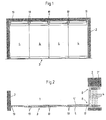
- An opening 1 in a wall 2 is closed by a sliding door 3.
- This sliding door 3 is arranged hanging and consists of a total of four wings 4.
- a double rail system is provided which is arranged at the top in the opening 1 of the wall 2 and in the wall recess 2 '.
- the double rail system has two mutually parallel rails 5, 5 'in the region of the opening 1.
- Each of the wings 4 is slidably mounted at one end on one rail 5 and at the other end on the other rail 5 '.
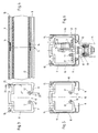
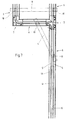
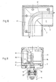
- the rail 5 ' branches off in the area of the wall recess 2' of the wall 2 at right angles to bend again in the original direction after passing through the width of the wall recess 2 '. This can be seen in the view in FIG. 2 and on an enlarged scale in the view in FIG. 7.
- the rear end of the wing 4 on the rail 5 is thus transported in a straight direction, while the front end of the wing 4' is transported at right angles to this by the branching of the rails 5, so that after passing through the kink the wings 4 run perpendicular to the plane of the sliding door 3 and are stacked one behind the other.
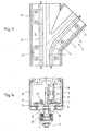
- FIG. 7 (with the associated FIGS. 8 to 11) a first embodiment and in FIG. 12 (with the associated FIGS. 13 to 16) a second embodiment.
- the difference is that in the first embodiment (corresponding to Fig. 2) the stacked wings 4 are perpendicular to the plane of the sliding door 3, while in the second embodiment the wings 4 are stacked such that they are parallel to the plane of the sliding door 3 extend.
- the basic structure of the double rail system is that components 6 for the linear double rails and components 7 for curved rail sections 8, that is, sections in which the rails 5,5 'branch or are curved, are provided. These components 6, 7 are formed completely separately from one another, the components 6 for the straight rail sections being so-called yard goods, which are cut to the appropriate length.
- the components 7 for the curved rail sections 8, on the other hand, are created individually and adapted to the required branches, curvatures, etc.
- both components 6, 7 each consist of a hollow box section 9 made of metal or plastic.
- the end view of such a hollow box profile 9 is shown in Fig. 3. It can be seen in this illustration that the hollow box profile 9 has a slot 10 on the underside. This is limited by two inwardly directed legs of the hollow box profile 9, which define base plates 11 for rail profiles 12.
- the rail profiles 12 are formed in one piece with the base plate 11 and thus in one piece with the hollow box profile 9.
- the rail profile 12 is on the top semi-cylindrical, ie round and has a longitudinal slot 13 in the lower area, so that the rail profile 12 is formed by a hollow profile open at the bottom.
- a joint S between two hollow box profiles 9 of two components 6,7 is shown in longitudinal section. It can be seen that 12 centering pins 14 are arranged between the hollow box profiles 9 in the region of the internally hollow rail profiles, which ensure an exact alignment of the rail profiles 12. Correspondingly, further centering pins 14 are provided in cutouts 15 in the upper region of the hollow box profiles 9. This ensures that the hollow box profiles 9 of the components 6, 7 abut each other exactly.
- Fig. 6 shows the basic principle of the device as in Fig. 5, with two exceptions.
- the rail profile 12 is not formed in one piece with the base plate 11 of the hollow box profile 9, but the rail profile 12 is a separate component.
- the rail profile 12 is a tube which is welded onto a support plate 17, the support plate 17 in turn being screwed onto the corresponding base plate 11 of the box section 9.
- a solid rod with pins can also be provided for centering.
- the formation of the rail profile 12 in this form forms the basic principle of the components 7 for the curved rail sections 8.
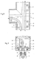
- a chassis 18 has a roller 19 in the upper region.
- the chassis 18 is through passed the slot 10 in the hollow box section 9 and is connected to the wing 4 via a ball bearing 20 pivotable about a vertical axis.
- the first embodiment of the double-rail system in FIG. 7 initially consists of a component 6, to which a component 7 with a curved rail section 8 is connected.
- This component 7 is followed by two components 6 in a right-angled arrangement, which are also designed as double rails.
- the angled branch then has a further component 7, in which the rail 5 'is guided at right angles in the original direction.
- a component 6 then connects to this component 7 again.
- the two components 7 of this embodiment are shown enlarged in FIGS. 8 and 9 and in FIGS. 10 and 11.
- the hollow box profile 9 is composed of individual hollow box profile elements, the rail profiles 12 being fastened with their carrier plates 17 on the base plate 11.
- the centering pins 14 can be seen at the ends, by means of which these components 7 can be connected to the subsequent components 6 with exact centering.
- the second embodiment in FIG. 12 is constructed in a corresponding manner.
- a component 6 is initially provided with a straight section for the rails 5,5 '.
- a component 7 which has a branch for the one rail 5 '(Fig. 13 and 14).
- Components 6 with straight rail sections are angled to one another.
- One component 6 finally has a component 7 with a bend in the rail 5 (FIGS. 15 and 16).
- the corresponding hollow box profiles 9 are composed accordingly are to get the turn or kink.
- the rail profiles 12 are screwed with their carrier plates 17 onto the base plates 11 of the box section 9.
- Components 6 and 7 according to the invention create a modular system by means of which the most varied of rail systems can be produced.
- the rail profile 12 for the straight rail sections in the components 6 with the underside longitudinal slot 13 represents an independent invention which is independent of the modular system described. This special rail profile ensures optimal running behavior of the chassis 18 with its roller 19.
Landscapes
- Engineering & Computer Science (AREA)
- Mechanical Engineering (AREA)
- Support Devices For Sliding Doors (AREA)
- Wing Frames And Configurations (AREA)
- Glass Compositions (AREA)
- Power-Operated Mechanisms For Wings (AREA)
- Lubricants (AREA)
- Lock And Its Accessories (AREA)
Applications Claiming Priority (2)
| Application Number | Priority Date | Filing Date | Title |
|---|---|---|---|
| DE4015870 | 1990-05-17 | ||
| DE4015870A DE4015870C2 (de) | 1990-05-17 | 1990-05-17 | Schiebetür |
Publications (2)
| Publication Number | Publication Date |
|---|---|
| EP0457286A1 EP0457286A1 (de) | 1991-11-21 |
| EP0457286B1 true EP0457286B1 (de) | 1994-06-29 |
Family
ID=6406622
Family Applications (1)
| Application Number | Title | Priority Date | Filing Date |
|---|---|---|---|
| EP91107811A Expired - Lifetime EP0457286B1 (de) | 1990-05-17 | 1991-05-15 | Schiebetür |
Country Status (5)
| Country | Link |
|---|---|
| EP (1) | EP0457286B1 (da) |
| AT (1) | ATE107997T1 (da) |
| DE (3) | DE4015870C2 (da) |
| DK (1) | DK0457286T3 (da) |
| ES (1) | ES2057656T3 (da) |
Cited By (1)
| Publication number | Priority date | Publication date | Assignee | Title |
|---|---|---|---|---|
| US20160138316A1 (en) * | 2014-11-14 | 2016-05-19 | Dorma Deutschland Gmbh | Cover holder |
Families Citing this family (24)
| Publication number | Priority date | Publication date | Assignee | Title |
|---|---|---|---|---|
| EP0572936B1 (de) * | 1992-06-04 | 1996-09-25 | Karl Haab | Schiene |
| DE4435641C2 (de) * | 1994-10-06 | 1998-12-03 | Juergen Guddas | Schiebeflügel zum bedarfsweisen Verschließen, insbesondere einer offenen Seite von Balkonen, Wintergärten u. dgl. |
| CH689233A5 (de) * | 1996-05-07 | 1998-12-31 | Dorma Tuerautomatik Ag | Schiebewand |
| DE19634391C5 (de) * | 1996-08-26 | 2016-07-21 | Dorma Deutschland Gmbh | Bodenverankerung für Flügel einer ortsveränderbaren Schiebeflügelwand aus Isolierglas |
| DE19727928C2 (de) * | 1997-07-01 | 2001-11-29 | Dorma Gmbh & Co Kg | An mindestens einer Laufschiene geführte Schiebewand |
| DE19734179C2 (de) * | 1997-08-07 | 1999-09-02 | Dorma Gmbh & Co Kg | An mindestens einer Laufschiene geführte Schiebewand |
| FI114656B (fi) * | 1997-12-19 | 2004-11-30 | Lumon Oy | Parvekelasitus |
| DE19828336B4 (de) * | 1998-06-25 | 2014-02-06 | Geze Gmbh | Laufwerk |
| ATE257541T1 (de) * | 1998-12-18 | 2004-01-15 | Peter Schmid | Laufschiene für ein schiebetor |
| DE19915188C2 (de) * | 1999-04-06 | 2001-04-19 | Dorma Gmbh & Co Kg | Laufschiene für eine aus mehreren Flügeln bestehende Schiebewand |
| DE19947705C2 (de) * | 1999-10-04 | 2003-04-30 | Dorma Gmbh & Co Kg | In einer Führungsschiene geführter Laufwagen |
| DE10024580A1 (de) | 2000-05-19 | 2001-11-22 | Dorma Gmbh & Co Kg | Laufschiene für ein aus mehreren Flügeln bestehendes Schiebewandsystem |
| FI109226B (fi) * | 2000-05-22 | 2002-06-14 | Iloxi Oy | Kannatusjärjestely |
| DE10052539B4 (de) | 2000-10-23 | 2004-09-30 | Dorma Gmbh + Co. Kg | Aus mehreren Schiebeflügeln gebildete Schiebewand |
| FR2829172B1 (fr) * | 2001-09-03 | 2004-12-10 | Baumert Ind | Dispositif de fermeture du type repliable en accordeon |
| ES2220218B1 (es) * | 2003-05-23 | 2006-02-16 | Klein Iberica, S.A. | Mecanismo para suspension y regulacion de puertas plegables. |
| FI119001B (fi) | 2006-08-16 | 2008-06-13 | Lumon Oy | Paneelijärjestelmä ja sen yläohjain |
| CH701501A1 (de) * | 2009-07-24 | 2011-01-31 | Eku Ag | Führungsschiene für eine Schiebetür. |
| US8613164B1 (en) * | 2011-01-11 | 2013-12-24 | David Barber | Hide-away closet door hardware |
| DE102014221440B3 (de) * | 2014-10-22 | 2016-04-21 | Geze Gmbh | Lager- und Führungseinrichtung einer Schiebewand- oder Schiebetüranlage |
| GB2560144B (en) * | 2016-11-17 | 2021-10-27 | Home Decor Gb Ltd | Modular track system |
| CN107605345B (zh) * | 2017-10-12 | 2019-11-08 | 舒旭 | 一种门窗的堆叠式结构及堆叠后自动清洗装置 |
| WO2019212389A1 (ru) * | 2018-05-03 | 2019-11-07 | Ermolayev Igor Aleksandrovich | Устройство закрытия архитектурного проема |
| RU190911U1 (ru) * | 2018-10-30 | 2019-07-16 | Игорь Александрович Ермолаев | Устройство закрытия архитектурного проёма |
Family Cites Families (6)
| Publication number | Priority date | Publication date | Assignee | Title |
|---|---|---|---|---|
| DE7528036U (de) * | 1975-09-05 | 1976-01-02 | Paul Hettich & Co, 4983 Kirchlengern | Fuehrungsbahnprofil eines schiebetuerbeschlages |
| DE2828691A1 (de) * | 1978-06-30 | 1980-01-03 | Richard Banse | Trag- und fuehrungsvorrichtung fuer gardinen, vorhaenge, haengende trennwaende o.dgl. |
| US4569164A (en) * | 1983-04-08 | 1986-02-11 | Advanced Equipment Corp. | Operable wall system |
| DE3610892A1 (de) * | 1986-03-24 | 1987-10-08 | Hubert Kurz | Sektionalschiebewand |
| DE3629369A1 (de) * | 1986-08-29 | 1988-03-03 | Rixen Wolfgang | Profilstab |
| ES2006134A6 (es) * | 1987-03-31 | 1989-04-16 | Klein Iberica | Herrajes para puertas corredizas y similares |
-
1990
- 1990-05-17 DE DE4015870A patent/DE4015870C2/de not_active Expired - Fee Related
- 1990-05-17 DE DE9007691U patent/DE9007691U1/de not_active Expired - Lifetime
-
1991
- 1991-05-15 EP EP91107811A patent/EP0457286B1/de not_active Expired - Lifetime
- 1991-05-15 DK DK91107811.1T patent/DK0457286T3/da active
- 1991-05-15 AT AT91107811T patent/ATE107997T1/de not_active IP Right Cessation
- 1991-05-15 DE DE59102057T patent/DE59102057D1/de not_active Expired - Fee Related
- 1991-05-15 ES ES91107811T patent/ES2057656T3/es not_active Expired - Lifetime
Cited By (1)
| Publication number | Priority date | Publication date | Assignee | Title |
|---|---|---|---|---|
| US20160138316A1 (en) * | 2014-11-14 | 2016-05-19 | Dorma Deutschland Gmbh | Cover holder |
Also Published As
| Publication number | Publication date |
|---|---|
| DE4015870C2 (de) | 1994-02-17 |
| ATE107997T1 (de) | 1994-07-15 |
| DK0457286T3 (da) | 1994-11-07 |
| ES2057656T3 (es) | 1994-10-16 |
| EP0457286A1 (de) | 1991-11-21 |
| DE4015870A1 (de) | 1991-11-21 |
| DE59102057D1 (de) | 1994-08-04 |
| DE9007691U1 (de) | 1994-04-14 |
Similar Documents
| Publication | Publication Date | Title |
|---|---|---|
| EP0457286B1 (de) | Schiebetür | |
| EP0946825A1 (de) | Laufschiene für ein laufwerk für eine hängend gelagerte trennwand | |
| DE2237600A1 (de) | Gliederfoerderband aus gelenkig miteinander verbundenen metallischen plattengliedern | |
| DE3245308A1 (de) | Foerderer mit leicht montierbaren traegerabschnitten | |
| DE2604882C2 (de) | Befahrbare Fläche für mechanische Parkeinrichtungen, Rampen, Hebebühnen o.dgl. | |
| DE9300855U1 (de) | Bausatz zur Standardisierung und Bildung eines Baukastensystems für Kettenförderer, Kettenstauförderer und/oder Zahnriemenförderer | |
| EP0385167A1 (de) | Seil-Umlenkstück | |
| DE68907768T2 (de) | Faltwand, bestehend aus miteinander gelenkig verbundenen doppelwandigen Flügeln. | |
| DE4407818C2 (de) | Aufhängevorrichtung für längs einer Tragschiene verfahrbare Flügel einer Schiebetür, Faltschiebetür oder dergleichen | |
| EP3625153A2 (de) | Plattenförderer und transportaufsatz für einen sochen plattenförderer | |
| DE102017011293B4 (de) | Laufbahn, Fördereinrichtung und Verfahren zur Montage einer Laufbahn | |
| DE8029667U1 (de) | Halteschiene fuer schleppkettenantrieb | |
| EP0019076B1 (de) | Führungsanordnung zum linearen Verstellen mindestens eines an einem Träger angeordneten Gegenstandes, insbesondere zur Parallelverstellung von Möbeleinschüben | |
| DE19934361A1 (de) | Werkstück-Transfersystem | |
| DE19732700A1 (de) | Antriebsvorrichtung für ein Deckelteil eines Fahrzeugdaches | |
| EP3088647A1 (de) | Schienenvorrichtung für eine führungsvorrichtung | |
| EP0074648B1 (de) | Rahmen für Bandfördervorrichtungen | |
| DE2923890C2 (de) | Kupplungsvorrichtung für Schleppkreisförderer | |
| EP0737791A1 (de) | Fahrschienenanordnung für verfahrbare Trennwandelemente | |
| DE8029666U1 (de) | Schleppkettenantrieb | |
| DE10045746A1 (de) | Streckeneinheit für ein Transfersystem | |
| DE4136154A1 (de) | Bandfoerdervorrichtung mit zusammengesetztem foerderbandrahmen | |
| EP0558820A1 (de) | Staurollengurtförderer | |
| DE3434195C1 (de) | Vorrichtung zum Anbringen eines länglichen Körpers, insbesondere eines Rohres | |
| EP0584084B1 (de) | Leichtmetall-gussteil und verfahren zu seiner herstellung |
Legal Events
| Date | Code | Title | Description |
|---|---|---|---|
| PUAI | Public reference made under article 153(3) epc to a published international application that has entered the european phase |
Free format text: ORIGINAL CODE: 0009012 |
|
| AK | Designated contracting states |
Kind code of ref document: A1 Designated state(s): AT BE CH DE DK ES FR GB GR IT LI LU NL SE |
|
| 17P | Request for examination filed |
Effective date: 19911211 |
|
| 17Q | First examination report despatched |
Effective date: 19920214 |
|
| GRAA | (expected) grant |
Free format text: ORIGINAL CODE: 0009210 |
|
| AK | Designated contracting states |
Kind code of ref document: B1 Designated state(s): AT BE CH DE DK ES FR GB GR IT LI LU NL SE |
|
| PG25 | Lapsed in a contracting state [announced via postgrant information from national office to epo] |
Ref country code: GR Free format text: LAPSE BECAUSE OF FAILURE TO SUBMIT A TRANSLATION OF THE DESCRIPTION OR TO PAY THE FEE WITHIN THE PRESCRIBED TIME-LIMIT Effective date: 19940629 |
|
| REF | Corresponds to: |
Ref document number: 107997 Country of ref document: AT Date of ref document: 19940715 Kind code of ref document: T |
|
| ET | Fr: translation filed | ||
| GBT | Gb: translation of ep patent filed (gb section 77(6)(a)/1977) |
Effective date: 19940701 |
|
| REF | Corresponds to: |
Ref document number: 59102057 Country of ref document: DE Date of ref document: 19940804 |
|
| ITF | It: translation for a ep patent filed | ||
| REG | Reference to a national code |
Ref country code: ES Ref legal event code: FG2A Ref document number: 2057656 Country of ref document: ES Kind code of ref document: T3 |
|
| REG | Reference to a national code |
Ref country code: DK Ref legal event code: T3 |
|
| REG | Reference to a national code |
Ref country code: GR Ref legal event code: FG4A Free format text: 3013178 |
|
| EAL | Se: european patent in force in sweden |
Ref document number: 91107811.1 |
|
| PLBE | No opposition filed within time limit |
Free format text: ORIGINAL CODE: 0009261 |
|
| STAA | Information on the status of an ep patent application or granted ep patent |
Free format text: STATUS: NO OPPOSITION FILED WITHIN TIME LIMIT |
|
| PG25 | Lapsed in a contracting state [announced via postgrant information from national office to epo] |
Ref country code: GB Effective date: 19950515 Ref country code: DK Effective date: 19950515 Ref country code: AT Effective date: 19950515 |
|
| REG | Reference to a national code |
Ref country code: DK Ref legal event code: EBP |
|
| PG25 | Lapsed in a contracting state [announced via postgrant information from national office to epo] |
Ref country code: SE Effective date: 19950516 Ref country code: ES Free format text: LAPSE BECAUSE OF NON-PAYMENT OF DUE FEES Effective date: 19950516 |
|
| PG25 | Lapsed in a contracting state [announced via postgrant information from national office to epo] |
Ref country code: LU Free format text: LAPSE BECAUSE OF NON-PAYMENT OF DUE FEES Effective date: 19950531 Ref country code: LI Effective date: 19950531 Ref country code: CH Effective date: 19950531 Ref country code: BE Effective date: 19950531 |
|
| 26N | No opposition filed | ||
| BERE | Be: lapsed |
Owner name: WILH. SCHLECHTENDAHL & SOHNE G.M.B.H. & CO. K.G. Effective date: 19950531 Owner name: HESPE & WOELM G.M.B.H. & CO. K.G. Effective date: 19950531 |
|
| PG25 | Lapsed in a contracting state [announced via postgrant information from national office to epo] |
Ref country code: NL Effective date: 19951201 |
|
| GBPC | Gb: european patent ceased through non-payment of renewal fee |
Effective date: 19950515 |
|
| REG | Reference to a national code |
Ref country code: CH Ref legal event code: PL Ref country code: GR Ref legal event code: MM2A Free format text: 3013178 |
|
| NLV4 | Nl: lapsed or anulled due to non-payment of the annual fee |
Effective date: 19951201 |
|
| PG25 | Lapsed in a contracting state [announced via postgrant information from national office to epo] |
Ref country code: DE Effective date: 19960201 |
|
| EUG | Se: european patent has lapsed |
Ref document number: 91107811.1 |
|
| PG25 | Lapsed in a contracting state [announced via postgrant information from national office to epo] |
Ref country code: FR Effective date: 19960229 |
|
| REG | Reference to a national code |
Ref country code: FR Ref legal event code: ST |
|
| REG | Reference to a national code |
Ref country code: FR Ref legal event code: ST |
|
| REG | Reference to a national code |
Ref country code: ES Ref legal event code: FD2A Effective date: 19990503 |
|
| PG25 | Lapsed in a contracting state [announced via postgrant information from national office to epo] |
Ref country code: IT Free format text: LAPSE BECAUSE OF NON-PAYMENT OF DUE FEES Effective date: 20050515 |