EP0457012B1 - Ablaufarmatur für Fussböden oder Dächer - Google Patents
Ablaufarmatur für Fussböden oder Dächer Download PDFInfo
- Publication number
- EP0457012B1 EP0457012B1 EP91105276A EP91105276A EP0457012B1 EP 0457012 B1 EP0457012 B1 EP 0457012B1 EP 91105276 A EP91105276 A EP 91105276A EP 91105276 A EP91105276 A EP 91105276A EP 0457012 B1 EP0457012 B1 EP 0457012B1
- Authority
- EP
- European Patent Office
- Prior art keywords
- pot
- drain
- steel
- plastic
- building
- Prior art date
- Legal status (The legal status is an assumption and is not a legal conclusion. Google has not performed a legal analysis and makes no representation as to the accuracy of the status listed.)
- Expired - Lifetime
Links
- 239000004033 plastic Substances 0.000 claims abstract description 24
- 229920003023 plastic Polymers 0.000 claims abstract description 24
- 229910000831 Steel Inorganic materials 0.000 claims abstract description 21
- 239000010959 steel Substances 0.000 claims abstract description 21
- XLYOFNOQVPJJNP-UHFFFAOYSA-N water Substances O XLYOFNOQVPJJNP-UHFFFAOYSA-N 0.000 claims abstract description 6
- 239000000463 material Substances 0.000 claims description 2
- 239000011888 foil Substances 0.000 claims 1
- 238000009413 insulation Methods 0.000 description 2
- 239000002184 metal Substances 0.000 description 2
- 229910000746 Structural steel Inorganic materials 0.000 description 1
- 230000004888 barrier function Effects 0.000 description 1
- 238000004519 manufacturing process Methods 0.000 description 1
Images
Classifications
-
- E—FIXED CONSTRUCTIONS
- E03—WATER SUPPLY; SEWERAGE
- E03F—SEWERS; CESSPOOLS
- E03F5/00—Sewerage structures
- E03F5/04—Gullies inlets, road sinks, floor drains with or without odour seals or sediment traps
- E03F5/0407—Floor drains for indoor use
-
- E—FIXED CONSTRUCTIONS
- E04—BUILDING
- E04D—ROOF COVERINGS; SKY-LIGHTS; GUTTERS; ROOF-WORKING TOOLS
- E04D13/00—Special arrangements or devices in connection with roof coverings; Protection against birds; Roof drainage ; Sky-lights
- E04D13/04—Roof drainage; Drainage fittings in flat roofs, balconies or the like
- E04D13/0404—Drainage on the roof surface
- E04D13/0409—Drainage outlets, e.g. gullies
-
- E—FIXED CONSTRUCTIONS
- E03—WATER SUPPLY; SEWERAGE
- E03F—SEWERS; CESSPOOLS
- E03F5/00—Sewerage structures
- E03F5/04—Gullies inlets, road sinks, floor drains with or without odour seals or sediment traps
- E03F2005/0412—Gullies inlets, road sinks, floor drains with or without odour seals or sediment traps with means for adjusting their position with respect to the surrounding surface
- E03F2005/0413—Gullies inlets, road sinks, floor drains with or without odour seals or sediment traps with means for adjusting their position with respect to the surrounding surface for height adjustment
-
- E—FIXED CONSTRUCTIONS
- E03—WATER SUPPLY; SEWERAGE
- E03F—SEWERS; CESSPOOLS
- E03F5/00—Sewerage structures
- E03F5/04—Gullies inlets, road sinks, floor drains with or without odour seals or sediment traps
- E03F2005/0416—Gullies inlets, road sinks, floor drains with or without odour seals or sediment traps with an odour seal
- E03F2005/0418—Gullies inlets, road sinks, floor drains with or without odour seals or sediment traps with an odour seal in the form of a bell siphon
-
- E—FIXED CONSTRUCTIONS
- E04—BUILDING
- E04D—ROOF COVERINGS; SKY-LIGHTS; GUTTERS; ROOF-WORKING TOOLS
- E04D13/00—Special arrangements or devices in connection with roof coverings; Protection against birds; Roof drainage ; Sky-lights
- E04D13/04—Roof drainage; Drainage fittings in flat roofs, balconies or the like
- E04D13/0404—Drainage on the roof surface
- E04D13/0409—Drainage outlets, e.g. gullies
- E04D2013/0427—Drainage outlets, e.g. gullies with means for controlling the flow in the outlet
-
- E—FIXED CONSTRUCTIONS
- E04—BUILDING
- E04D—ROOF COVERINGS; SKY-LIGHTS; GUTTERS; ROOF-WORKING TOOLS
- E04D13/00—Special arrangements or devices in connection with roof coverings; Protection against birds; Roof drainage ; Sky-lights
- E04D13/04—Roof drainage; Drainage fittings in flat roofs, balconies or the like
- E04D13/0404—Drainage on the roof surface
- E04D13/0409—Drainage outlets, e.g. gullies
- E04D2013/0436—Drainage outlets, e.g. gullies with sealing means
Definitions
- the invention relates to a drain fitting for floors or roofs according to the preamble of the main claim (see. DE-A-2803959).
- Drain fittings of this type are installed to absorb the water from floors or roofs and pass the water flow on to a drain pipe.
- the pots which have an odor trap as floor drain fittings, are made of plastic.
- the drain pipes which generally also consist of plastic, are connected directly to a nozzle of the pot according to the prior art.
- the invention has for its object to design drain fittings for floors or roofs so that such a risk is prevented.
- the subclaim has a preferred embodiment, in particular for floor drains.
- the drain pipeline is not connected directly to the pot made of plastic, but to the socket of the steel pot holding the plastic pot. Since this steel does not burn, the flame can therefore no longer advance to the plastic pot, so that the further spread of the fire is stopped.
- the steel pot is first fixed on site, for example poured into the concrete or connected to the roof structure, after which the plastic pot is freely inserted into the steel pot from above. It is possible to adjust the height of the plastic pot to the height of the water-absorbing surface.
- the plastic pot is "floating" in the steel pot, ie it is held by the rubber ring alone and there is a distance between the pot walls. With this arrangement, impacts and vibrations acting on the screed or the grate of the plastic pot are not transmitted to the concrete, but are dampened by impact sound mats or by the rubber ring.
- FIGS. 1 and 2 will be described.
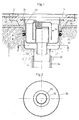
- This fitting has two pots, namely an upper pot 20 made of plastic and a lower pot 30 made of steel, which receives the smaller plastic pot with the same axis.
- a rubber ring 32 held in a groove 31 of the steel pot, lies all around on the outside of the wall of the plastic pot 20.
- Drainage nozzles 23 and 33 are formed on the steel pot as well as on the plastic pot 20, with a drainage pipe 34 made of plastic that connects the water to the drainage nozzle 33 of the steel pot.
- the steel pot is poured into the concrete 1.
- the plastic pot is inserted concentrically into the steel pot from above and held in place by the rubber ring.
- Impact sound mats 2 are placed on the surface of the concrete, which lie against the protruding wall of the plastic pot.
- the plastic pot 20 forms a manufacturing unit with a concrete plate 10, which is square in plan view, in which the upper part of the pot is cast with its collar 21.
- the concrete slab 10 is laid in the area of a screed 3 which is applied to the impact sound mats 2.
- Structural steel mats 12 cast into the concrete slab 10 create a bond with the screed.
- An insulating film can be placed on the surface of the screed.
- a stepped ring surface 11 is formed on the concrete slab 10, where a cover grille can be placed directly or a frame (not shown) into which a grate is inserted.
- a shoulder 22 is formed, where a cylindrical attachment part can be placed, which carries the grate on top, which must lie at the height of the tiles.
- the pot 20 receives known elements 24 for the odor trap.
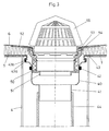
- FIG. 3 shows a drain fitting which is installed in a roof structure consisting of trapezoidal sheet metal 4 and which has the task of absorbing the water coming from the roof surface and passing it on to a drain pipe 44.
- a steel pot 40 with a special profile is provided, which is installed in a fixed manner in the roof structure (trapezoidal sheet 4).
- the plastic drain pipe 44 is connected to a nozzle 41 of the steel pot.
- a rubber ring 42 is received by a groove in the steel pot.
- a snap ring (43b), which is received by a groove (43a) formed in the steel pot, is provided for holding a film (7) which lies on the roof structure and serves as a vapor barrier.
- a plastic pot 50 is inserted into the steel pot and held by the rubber ring.
- the roofing felt 6 on the thermal insulation 5 is placed on a collar 52 of the pot 50 and clamped in a manner known per se with a ring 54.
- the seal between this ring and the pot is provided by a lip seal 53.
- a leaf collecting basket 55 is placed on the ring. Characterized in that the pot 50 is slidably inserted, it is possible to adjust the height of the collar 52 to the thickness of the thermal insulation 5.
Landscapes
- Engineering & Computer Science (AREA)
- Architecture (AREA)
- Life Sciences & Earth Sciences (AREA)
- Hydrology & Water Resources (AREA)
- Public Health (AREA)
- Water Supply & Treatment (AREA)
- Health & Medical Sciences (AREA)
- Civil Engineering (AREA)
- Structural Engineering (AREA)
- Floor Finish (AREA)
- Building Environments (AREA)
- Fertilizing (AREA)
- Sink And Installation For Waste Water (AREA)
Description
- Die Erfindung bezieht sich auf eine Ablaufarmatur für Fußböden oder Dächer nach dem Oberbegriff des Hauptanspruchs (vgl. DE-A-2803959).
- Ablaufarmaturen dieser Art werden zur Aufnahme des Wassers von Fußböden oder von Dächern eingebaut und geben den Wasserstrom an eine Ablauf-Rohrleitung weiter. Die Töpfe, die als Bodenablaufarmaturen einen Geruchsverschluß haben, bestehen aus Kunststoff. Die Ablauf-Rohrleitungen, die im allgemeinen aus auch Kunststoff bestehen, sind nach dem Stand der Technik direkt an einen Stutzen des Topfes angeschlossen. Die Tatsache, daß sowohl die Ablauf-Rohrleitung als auch der Topf aus Kunststoff, also einem brennbaren Werkstoff bestehen, bringt die Gefahr mit sich, daß im Falle eines Brandes das Feuer von der Rohrleitung auf den Topf übergreift und sich auf diesem Wege von einen Stockwerk in das nächste fortpflanzen kann.
- Der Erfindung liegt die Aufgabe zugrunde, Ablaufarmaturen für Fußböden oder Dächer so auszubilden, daß einer solchen Gefahr vorgebeugt wird.
- Diese Aufgabe wird durch eine Ablaufarmatur mit den Merkmalen des Hauptanspruchs gelöst. Der Unteranspruch hat eine bevorzugte Ausführungsform, insbesondere für Fußbodenabläufe zum Inhalt.
- Bei einer solchen Ablaufarmatur ist die Ablauf-Rohrleitung nicht direkt an den aus Kunststoff bestehenden Topf angeschlossen, sondern an den Stutzen des den Kunststofftopf aufnehmenden Stahltopfes. Da dieser Stahl nicht brennt, kann die Flamme somit an den Topf aus Kunststoff nicht weiter vordringen, so daß der weiteren Ausbreitung des Brandes Einhalt geboten ist. Bei der Montage wird zunächst der Stahltopf bauseitig fest angebracht, beispielsweise in den Beton eingegossen oder mit der Dachkonstruktion verbunden, wonach der Kunststofftopf von oben frei in den Stahltopf eingesetzt wird. Dabei besteht die Möglichkeit die Höhenlage des Kunststofftopfes auf die Höhenlage der wasseraufnehmenden Oberfläche einzustellen.
- Bei einer bevorzugten Ausführungsform der Erfindung ist der Kunststofftopf "schwimmend" in den Stahltopf eingesetzt, d. h. er wird allein durch den Gummiring gehalten und zwischen den Topfwänden ist Abstand eingehalten. Bei dieser Anordnung werden auf den Estrich bzw. auf den Rost des Kunststofftopfes einwirkende Stöße und Erschütterungen nicht auf den Beton übertragen, sondern durch Trittschallmatten bzw. durch den Gummiring gedämpft.
- Im folgenden werden Ausführungsbeispiele der Erfindung beschrieben unter Bezugnahme auf die beiliegenden Zeichnungen.
- Fig. 1
- zeigt in einem lotrechten Schnitt einer Bodenablaufarmatur nach der Erfindung eingebaut in einen Fliesenfußboden;
- Fig. 2
- zeigt einen Schnitt, gemäß II-II von Fig. 1;
- Fig. 3
- ist ein lotrechter Schnitt durch eine Dachablaufarmatur nach der Erfindung, eingebaut in eine aus Trapezblech bestehende tragende Konstruktion.
- Zunächst wird das Ausführungsbeispiel nach Fig. 1 und 2 beschrieben.
- Diese Armatur hat zwei Töpfe, nämlich einen oberen Topf 20 aus Kunststoff und einen unteren Topf 30 aus Stahl, der achsgleich den kleineren Kunststofftopf aufnimmt. Dabei liegt ein Gummiring 32, in einer Nut 31 des Stahltopfes gehalten, ringsum außen an der Wand des Kunststofftopfes 20 an. Sowohl am Stahltopf als auch am Kunststofftopf 20 sind achsgleich Ablaufstutzen 23 bzw. 33 angeformt, wobei eine das Wasser weiterführende Ablauf-Rohrleitung 34 aus Kunststoff an den Ablaufstutzen 33 des Stahltopfes angeschlossen ist.
- Der Stahltopf ist in den Beton 1 eingegossen. Bei der Montage wird der Kunststofftopf von oben in den Stahltopf konzentrisch eingesetzt und dabei durch die Anlage des Gummiringes gehalten. Auf der Oberfläche des Betons sind Trittschallmatten 2 aufgelegt, die an der überstehenden Wand des Kunststofftopfes anliegen.
- Der Kunststofftopf 20 bildet eine fabrikatorische Einheit mit einer in der Draufsicht quadratischen Betonplatte 10, in welcher der obere Teil des Topfes mit seinem Kragen 21 eingegossen ist. Die Betonplatte 10 wird im Bereich eines Estrich 3 verlegt, der auf die Trittschallmatten 2 aufgebracht ist. Dabei stellen in die Betonplatte 10 eingegossene Baustahlmatten 12 einen Verbund mit dem Estrich her. Auf die Oberfläche des Estrich kann eine Isolierfolie aufgelegt werden.
- An der Betonplatte 10 ist eine abgesetzte Ringfläche 11 gebildet, wo direkt ein Abdeckrost aufgelegt werden kann oder ein nicht dargestellter Rahmen, in den ein Rost eingesetzt wird. Oben am Topf 20 ist ein Absatz 22 gebildet, wo ein zylindrisches Aufsatzteil aufgelegt werden kann, das oben den Rost trägt, der in Höhe der Fliesen liegen muß. Der Topf 20 nimmt an sich bekannte Elemente 24 für den Geruchsverschluß auf.
- Auf Fig. 3 ist eine Ablaufarmatur dargestellt, die in eine aus Trapezblech 4 bestehende Dachkonstruktion eingebaut ist und die Aufgabe hat, das von der Dachoberfläche kommende Wasser aufzunehmen und in eine Ablauf-Rohrleitung 44 weiterzuleiten.
- Auch in diesem Falle ist ein Stahltopf 40 mit einem speziellen Profil vorgesehen, der ortsfest in die Dachkonstruktion (Trapezblech 4) eingebaut ist. Die aus Kunststoff bestehende Ablauf-Rohrleitung 44 ist an einen Stutzen 41 des Stahltopfes angeschlossen. Ein Gummiring 42 wird von einer Nut des Stahltopfes aufgenommen. Zum Festhalten einer Folie (7), die auf der Dachkonstruktion liegt und als Dampfsperre dient, ist ein Sprengring (43b) vorgesehen, der von einer im Stahltopf angeformten Nut (43a) aufgenommen ist.
- In den Stahltopf ist ein Topf 50 aus Kunststoff passend eingesetzt und gehalten durch den anliegenden Gummiring. Die Dachpappe 6 auf der Wärmedämmung 5 ist auf einen Kragen 52 des Topfes 50 aufgelegt, und in an sich bekannter Weise mit einem Ring 54 festgeklemmt. Die Abdichtung zwischen diesem Ring und dem Topf erfolgt durch eine Lippendichtung 53. Auf dem Ring ein Laubfangkorb 55 aufgesetzt. Dadurch, daß der Topf 50 verschiebbar eingesetzt ist, besteht die Möglichkeit, die Höhenlage des Kragens 52 der Dicke der Wärmedämmung 5 anzupassen.
Claims (4)
- Ablaufarmatur für Fußböden oder Dächer- mit einem bauseitig anbringbaren Topf (30, 40), an dessen Boden ein Ablaufstutzen (33, 51) zum Anschluß einer gebäudeseitigen Ablauf-Rohrleitung (34, 44) angeformt ist;- sowie einem höhenverstellbaren Topf (20, 50), geeignet zur Aufnahme des abfließenden Wassers, der konzentrisch von dem bauseitigen Topf aufgenommen und von einem diesen berührenden Ring gehalten ist;dadurch gekennzeichnet, daß der höhenverstellbare Topf (20, 50) aus Kunststoff besteht, der bauseitig anbringbare Topf (30, 40) ein Stahltopf ist und eine Nut (31) desselben den aus Gummi bestehenden Ring (32) aufnimmt.
- Ablaufarmatur nach Anspruch 1, dadurch gekennzeichnet, daß zwischen der Wand des Kunststofftopfes (20) und der Wand des Stahltopfes (30) Abstand eingehalten ist.
- Ablaufarmatur für Dächer nach Anspruch 1, dadurch gekennzeichnet, daß am Stahltopf (40) in Randnähe eine Nut (43a) angeformt ist, mit einem Sprengring (43b) mit dem eine als Dampfsperre dienende Folie (7) anklemmbar ist.
- Ablaufarmatur für Fußböden nach Anspruch 1, dadurch gekennzeichnet, daß der höhenverstellbare Topf (20) an sich bekannte Elemente (24) für den Geruchsverschluß aufnimmt.
Priority Applications (1)
| Application Number | Priority Date | Filing Date | Title |
|---|---|---|---|
| AT91105276T ATE90756T1 (de) | 1990-05-14 | 1991-04-03 | Ablaufarmatur fuer fussboeden oder daecher. |
Applications Claiming Priority (2)
| Application Number | Priority Date | Filing Date | Title |
|---|---|---|---|
| DE4015393A DE4015393A1 (de) | 1990-05-14 | 1990-05-14 | Ablaufarmatur fuer fussboeden oder daecher |
| DE4015393 | 1990-05-14 |
Publications (2)
| Publication Number | Publication Date |
|---|---|
| EP0457012A1 EP0457012A1 (de) | 1991-11-21 |
| EP0457012B1 true EP0457012B1 (de) | 1993-06-16 |
Family
ID=6406326
Family Applications (1)
| Application Number | Title | Priority Date | Filing Date |
|---|---|---|---|
| EP91105276A Expired - Lifetime EP0457012B1 (de) | 1990-05-14 | 1991-04-03 | Ablaufarmatur für Fussböden oder Dächer |
Country Status (3)
| Country | Link |
|---|---|
| EP (1) | EP0457012B1 (de) |
| AT (1) | ATE90756T1 (de) |
| DE (2) | DE4015393A1 (de) |
Cited By (1)
| Publication number | Priority date | Publication date | Assignee | Title |
|---|---|---|---|---|
| CN104452951A (zh) * | 2014-12-08 | 2015-03-25 | 国家电网公司 | 排水地漏 |
Families Citing this family (14)
| Publication number | Priority date | Publication date | Assignee | Title |
|---|---|---|---|---|
| DE4406782B4 (de) * | 1994-03-02 | 2004-07-15 | Dallmer Gmbh & Co. Kg | Ablaufarmatur für Fußböden und Decken |
| DE4406783B4 (de) * | 1994-03-02 | 2004-02-12 | Dallmer Gmbh & Co. Kg | Ablaufarmatur für Decken und Fußböden sowie Anordnung einer derartigen Ablaufarmatur in einer Deckenöffnung einer Deckenplatte |
| DE4430039C2 (de) * | 1994-08-24 | 1998-07-16 | Johann Franz Wach | Bodenablaufelement zum Einbau in eine Geschoßbodendurchführung |
| DE19510955A1 (de) * | 1995-03-25 | 1996-09-26 | Dallmer Gmbh & Co | Dachablaufarmatur |
| DE29619265U1 (de) * | 1996-11-05 | 1996-12-19 | Wiedemann GmbH, 25813 Husum | Sinkkasten mit Geruchsverschluß |
| AT407168B (de) * | 1998-10-23 | 2001-01-25 | Aschl Roman Ing | Bodenablauf für ein bauwerk |
| DE20101589U1 (de) * | 2001-01-31 | 2001-03-22 | Franz Viegener II GmbH & Co. KG, 57439 Attendorn | Ablauf |
| DE20217152U1 (de) * | 2002-11-07 | 2003-01-16 | Wiedemann GmbH, 25813 Husum | Sinkkasten mit Einbaugehäuse und Geruchsverschluß |
| DE202005021685U1 (de) * | 2005-02-02 | 2009-03-19 | Aco Severin Ahlmann Gmbh & Co. Kg | Ablaufschalung |
| DE202007008019U1 (de) * | 2007-06-05 | 2008-10-16 | Raimund Höllein Carolinenhütte GmbH | Entwässerungssystem |
| DE102007043327A1 (de) * | 2007-09-12 | 2009-03-19 | Dallmer Gmbh & Co. Kg | Ablaufvorrichtung für die zumindest teilweise Einbringung in einen Boden eines Raumes |
| SE534379C2 (sv) * | 2009-12-04 | 2011-08-02 | Purus Ab | Förfarande för anbringning av ett avlopp i ett golv samt anordning för användning vid detta förfarande. |
| DE102010030836B4 (de) | 2010-07-01 | 2014-12-31 | Tece Gmbh | Brandschutz für Bodenablauf |
| CN104631606B (zh) * | 2015-02-05 | 2016-03-02 | 太原金德尔洁具设备有限公司 | 虹吸式大流量水封防臭地漏 |
Family Cites Families (6)
| Publication number | Priority date | Publication date | Assignee | Title |
|---|---|---|---|---|
| DE1811391U (de) * | 1959-09-19 | 1960-05-12 | Walther Loeffler | Entwaesserungskoerper. |
| CH461391A (de) * | 1966-08-09 | 1968-08-15 | Esser Kg Klaus | Dachwassereinlauf |
| DE2315574A1 (de) * | 1973-03-28 | 1974-10-17 | Schoop & Co Ag | Wasserablauf |
| DE2803959C2 (de) * | 1978-01-30 | 1983-05-05 | Passavant-Werke AG & Co KG, 6209 Aarbergen | Höhenverstellbarer Boden- oder Deckenablauf |
| DE7931426U1 (de) * | 1979-11-07 | 1980-02-21 | Blancke, Robert, 6239 Eppstein | Sinkkasten fuer bodenablaufrinnen |
| DE8808648U1 (de) * | 1988-07-06 | 1988-09-01 | Kellner, Theodor, Dr.-Ing., 4223 Voerde | Feuerschutzklappe |
-
1990
- 1990-05-14 DE DE4015393A patent/DE4015393A1/de not_active Withdrawn
-
1991
- 1991-04-03 DE DE9191105276T patent/DE59100151D1/de not_active Expired - Fee Related
- 1991-04-03 AT AT91105276T patent/ATE90756T1/de not_active IP Right Cessation
- 1991-04-03 EP EP91105276A patent/EP0457012B1/de not_active Expired - Lifetime
Cited By (1)
| Publication number | Priority date | Publication date | Assignee | Title |
|---|---|---|---|---|
| CN104452951A (zh) * | 2014-12-08 | 2015-03-25 | 国家电网公司 | 排水地漏 |
Also Published As
| Publication number | Publication date |
|---|---|
| EP0457012A1 (de) | 1991-11-21 |
| DE4015393A1 (de) | 1991-11-21 |
| DE59100151D1 (de) | 1993-07-22 |
| ATE90756T1 (de) | 1993-07-15 |
Similar Documents
| Publication | Publication Date | Title |
|---|---|---|
| EP0457012B1 (de) | Ablaufarmatur für Fussböden oder Dächer | |
| DE102019007427A1 (de) | Profilsystem zur Halterung eines Flächenelements | |
| EP3056632A1 (de) | Randeinfassung für balkon- und terrassenböden | |
| DE9004119U1 (de) | Drain-Abschlußprofil | |
| EP2184415B1 (de) | Bodengleiche Ablaufvorrichtung für Einbau in Dusche oder Nasszelle | |
| CH666307A5 (de) | Trennelement fuer betonplatten. | |
| EP1362961B1 (de) | Bauelement für den Brandschutz einer Ablaufvorrichtung sowie Ablaufvorrichtung mit einem derartigen Bauelement | |
| DE3737767C2 (de) | ||
| EP3812531B1 (de) | Profilsystem zur halterung eines flächenelements | |
| DE102017105381A1 (de) | Bodenablauf und Bodenaufbau mit einem solchen Bodenablauf | |
| DE102010030836B4 (de) | Brandschutz für Bodenablauf | |
| CH701903A2 (de) | Verkleidungs- und Entwässerungselement für die Stirnseiten von Bauteilen wie Balkone, Terrassen, Laubengänge, Flachdächer und dergleichen. | |
| EP1210897A2 (de) | Trägerkörper für ein Duschtasse | |
| DE4406783B4 (de) | Ablaufarmatur für Decken und Fußböden sowie Anordnung einer derartigen Ablaufarmatur in einer Deckenöffnung einer Deckenplatte | |
| DE202009015093U1 (de) | Dusche, insbesondere bodengleiche Dusche | |
| DE102005031674B4 (de) | Anbaubalkon und Wassereinlaufkasten für denselben | |
| CH698095A2 (de) | Ablaufvorrichtung für eine Flüssigkeit mit einer Zarge. | |
| DE2103223C3 (de) | Isoliereinrichtung für begehbare, vorstehende Gebäudeteile, wie Balkone, Terrassen o.dgl. | |
| DE8814638U1 (de) | Nachträglich anbaubarer Balkon | |
| DE29606490U1 (de) | Abschlußprofil zur Begrenzung von Balkon- oder Terrassenbelägen | |
| EP1762665B1 (de) | Wand- oder Deckenkonstruktion in Trockenbauweise | |
| DE10112546C2 (de) | Entwässerungseinrichtung sowie Verfahren zur Herstellung einer Entwässerungsanordnung | |
| DE29616665U1 (de) | Balkon | |
| DE10315559A1 (de) | Verfahren und Vorrichtung zum Sanieren einer Schachtanlage | |
| DE29719728U1 (de) | Im Boden angeordnete Ablaufelemente, wie Bodenablaufrinnen, Bodenabläufe und Rohrdurchführungen |
Legal Events
| Date | Code | Title | Description |
|---|---|---|---|
| PUAI | Public reference made under article 153(3) epc to a published international application that has entered the european phase |
Free format text: ORIGINAL CODE: 0009012 |
|
| 17P | Request for examination filed |
Effective date: 19910920 |
|
| AK | Designated contracting states |
Kind code of ref document: A1 Designated state(s): AT BE CH DE DK FR IT LI NL SE |
|
| 17Q | First examination report despatched |
Effective date: 19920506 |
|
| GRAA | (expected) grant |
Free format text: ORIGINAL CODE: 0009210 |
|
| AK | Designated contracting states |
Kind code of ref document: B1 Designated state(s): AT BE CH DE DK FR IT LI NL SE |
|
| PG25 | Lapsed in a contracting state [announced via postgrant information from national office to epo] |
Ref country code: IT Free format text: LAPSE BECAUSE OF FAILURE TO SUBMIT A TRANSLATION OF THE DESCRIPTION OR TO PAY THE FEE WITHIN THE PRE;WARNING: LAPSES OF ITALIAN PATENTS WITH EFFECTIVE DATE BEFORE 2007 MAY HAVE OCCURRED AT ANY TIME BEFORE 2007. THE CORRECT EFFECTIVE DATE MAY BE DIFFERENT FROM THE ONE RECORDED.SCRIBED TIME-LIMIT Effective date: 19930616 Ref country code: FR Effective date: 19930616 Ref country code: DK Effective date: 19930616 Ref country code: SE Effective date: 19930616 |
|
| REF | Corresponds to: |
Ref document number: 90756 Country of ref document: AT Date of ref document: 19930715 Kind code of ref document: T |
|
| REF | Corresponds to: |
Ref document number: 59100151 Country of ref document: DE Date of ref document: 19930722 |
|
| EN | Fr: translation not filed | ||
| PLBE | No opposition filed within time limit |
Free format text: ORIGINAL CODE: 0009261 |
|
| STAA | Information on the status of an ep patent application or granted ep patent |
Free format text: STATUS: NO OPPOSITION FILED WITHIN TIME LIMIT |
|
| 26N | No opposition filed | ||
| PGFP | Annual fee paid to national office [announced via postgrant information from national office to epo] |
Ref country code: CH Payment date: 20040312 Year of fee payment: 14 |
|
| PGFP | Annual fee paid to national office [announced via postgrant information from national office to epo] |
Ref country code: NL Payment date: 20040316 Year of fee payment: 14 |
|
| PGFP | Annual fee paid to national office [announced via postgrant information from national office to epo] |
Ref country code: BE Payment date: 20040506 Year of fee payment: 14 |
|
| PG25 | Lapsed in a contracting state [announced via postgrant information from national office to epo] |
Ref country code: LI Free format text: LAPSE BECAUSE OF NON-PAYMENT OF DUE FEES Effective date: 20050430 Ref country code: CH Free format text: LAPSE BECAUSE OF NON-PAYMENT OF DUE FEES Effective date: 20050430 Ref country code: BE Free format text: LAPSE BECAUSE OF NON-PAYMENT OF DUE FEES Effective date: 20050430 |
|
| BERE | Be: lapsed |
Owner name: FIRMA *DALLMER G.M.B.H. & CO. Effective date: 20050430 |
|
| PG25 | Lapsed in a contracting state [announced via postgrant information from national office to epo] |
Ref country code: NL Free format text: LAPSE BECAUSE OF NON-PAYMENT OF DUE FEES Effective date: 20051101 |
|
| REG | Reference to a national code |
Ref country code: CH Ref legal event code: PL |
|
| NLV4 | Nl: lapsed or anulled due to non-payment of the annual fee |
Effective date: 20051101 |
|
| BERE | Be: lapsed |
Owner name: FIRMA *DALLMER G.M.B.H. & CO. Effective date: 20050430 |
|
| PGFP | Annual fee paid to national office [announced via postgrant information from national office to epo] |
Ref country code: AT Payment date: 20080311 Year of fee payment: 18 |
|
| PGFP | Annual fee paid to national office [announced via postgrant information from national office to epo] |
Ref country code: DE Payment date: 20090430 Year of fee payment: 19 |
|
| PG25 | Lapsed in a contracting state [announced via postgrant information from national office to epo] |
Ref country code: AT Free format text: LAPSE BECAUSE OF NON-PAYMENT OF DUE FEES Effective date: 20090403 |
|
| PG25 | Lapsed in a contracting state [announced via postgrant information from national office to epo] |
Ref country code: DE Free format text: LAPSE BECAUSE OF NON-PAYMENT OF DUE FEES Effective date: 20101103 |