EP0440846B1 - Seringue à chambre double et procédure d'emploi - Google Patents
Seringue à chambre double et procédure d'emploi Download PDFInfo
- Publication number
- EP0440846B1 EP0440846B1 EP90102373A EP90102373A EP0440846B1 EP 0440846 B1 EP0440846 B1 EP 0440846B1 EP 90102373 A EP90102373 A EP 90102373A EP 90102373 A EP90102373 A EP 90102373A EP 0440846 B1 EP0440846 B1 EP 0440846B1
- Authority
- EP
- European Patent Office
- Prior art keywords
- syringe
- needle
- plunger
- chamber
- plug
- Prior art date
- Legal status (The legal status is an assumption and is not a legal conclusion. Google has not performed a legal analysis and makes no representation as to the accuracy of the status listed.)
- Expired - Lifetime
Links
- 238000000034 method Methods 0.000 title claims description 11
- 239000002904 solvent Substances 0.000 claims abstract description 22
- 238000013016 damping Methods 0.000 claims abstract description 11
- 238000002347 injection Methods 0.000 claims abstract description 5
- 239000007924 injection Substances 0.000 claims abstract description 5
- 239000011521 glass Substances 0.000 claims description 6
- 239000000126 substance Substances 0.000 claims description 6
- 238000006073 displacement reaction Methods 0.000 claims description 5
- 239000003814 drug Substances 0.000 claims description 4
- 239000011149 active material Substances 0.000 claims 3
- 241000220317 Rosa Species 0.000 claims 1
- 230000002093 peripheral effect Effects 0.000 claims 1
- 239000013543 active substance Substances 0.000 abstract description 7
- 239000004480 active ingredient Substances 0.000 description 13
- 239000011324 bead Substances 0.000 description 4
- 238000004090 dissolution Methods 0.000 description 2
- 229940071643 prefilled syringe Drugs 0.000 description 2
- 239000000243 solution Substances 0.000 description 2
- 239000008186 active pharmaceutical agent Substances 0.000 description 1
- 238000002360 preparation method Methods 0.000 description 1
Images
Classifications
-
- A—HUMAN NECESSITIES
- A61—MEDICAL OR VETERINARY SCIENCE; HYGIENE
- A61M—DEVICES FOR INTRODUCING MEDIA INTO, OR ONTO, THE BODY; DEVICES FOR TRANSDUCING BODY MEDIA OR FOR TAKING MEDIA FROM THE BODY; DEVICES FOR PRODUCING OR ENDING SLEEP OR STUPOR
- A61M5/00—Devices for bringing media into the body in a subcutaneous, intra-vascular or intramuscular way; Accessories therefor, e.g. filling or cleaning devices, arm-rests
- A61M5/178—Syringes
- A61M5/31—Details
- A61M5/315—Pistons; Piston-rods; Guiding, blocking or restricting the movement of the rod or piston; Appliances on the rod for facilitating dosing ; Dosing mechanisms
- A61M5/31596—Pistons; Piston-rods; Guiding, blocking or restricting the movement of the rod or piston; Appliances on the rod for facilitating dosing ; Dosing mechanisms comprising means for injection of two or more media, e.g. by mixing
-
- A—HUMAN NECESSITIES
- A61—MEDICAL OR VETERINARY SCIENCE; HYGIENE
- A61M—DEVICES FOR INTRODUCING MEDIA INTO, OR ONTO, THE BODY; DEVICES FOR TRANSDUCING BODY MEDIA OR FOR TAKING MEDIA FROM THE BODY; DEVICES FOR PRODUCING OR ENDING SLEEP OR STUPOR
- A61M5/00—Devices for bringing media into the body in a subcutaneous, intra-vascular or intramuscular way; Accessories therefor, e.g. filling or cleaning devices, arm-rests
- A61M5/178—Syringes
- A61M5/31—Details
- A61M5/315—Pistons; Piston-rods; Guiding, blocking or restricting the movement of the rod or piston; Appliances on the rod for facilitating dosing ; Dosing mechanisms
- A61M5/31565—Administration mechanisms, i.e. constructional features, modes of administering a dose
- A61M5/31576—Constructional features or modes of drive mechanisms for piston rods
- A61M5/31583—Constructional features or modes of drive mechanisms for piston rods based on rotational translation, i.e. movement of piston rod is caused by relative rotation between the user activated actuator and the piston rod
- A61M5/31586—Constructional features or modes of drive mechanisms for piston rods based on rotational translation, i.e. movement of piston rod is caused by relative rotation between the user activated actuator and the piston rod performed by rotationally moving or pivoted actuator, e.g. an injection lever or handle
Definitions
- the invention relates to a process for mixing a pharmaceutical substance filled in a double-chamber syringe, the active ingredient of which is in dry form in one, needle-side chamber and the solvent of which is in the other chamber, the two chambers being separated from one another by a stopper which is used for Mixing of the substance with the solvent before application is adjustable in the area of a by-pass provided in the syringe barrel and extending in its axial direction, the length of which is greater than the axial height of the stopper, wherein the stopper is displaced towards the needle end via the syringe plunger delimiting the second chamber and provided with a piston rod, or directly or via the solvent.
- the invention further relates to a syringe for carrying out the method.
- EP-A-0 328 699 discloses a double-chamber syringe which ensures that the solvent can be transferred from one chamber to the other chamber containing the active ingredient in dry form at a limited speed. This ensures that parts of the solvent or of the active ingredient cannot escape from the syringe batch in advance as a result of the solvent flow rate being too high.
- This syringe has proven itself in practice for readily soluble active ingredients. In the case of poorly soluble active ingredients, however, care must be taken to ensure that the active ingredient has completely dissolved before the syringe is applied.
- the invention has for its object a method of the above.
- a method which achieves this object is characterized in that in the case of a vertical arrangement with the needle tip end pointing upward, the stopper is first moved into the by-pass area at a device-limited speed, in such a way that the The syringe plunger is freely movable against a front stop until it rests against the stopper, thereby transferring the solvent into the needle-side chamber, which is then pulled back one or more times until a complete stop of the plunger rod until the substance of the syringe is completely dissolved and then adjusted again to the front stop so that the active substance with the solvent flows from the front chamber via the bypass into the rear chamber and then back into the front chamber, and that finally after the active substance has completely dissolved, the displacement of the Syringe plunger up to the needle-side end of the syringe barrel first limiting front stop of the piston rod for application of the pharmaceutical substance is released.
- the progress achieved by the invention consists essentially in the fact that the complete dissolution of the active ingredient is ensured by a very simple handling of the syringe. Depending on the solubility of the substance, it can be specified how often the syringe plunger has to be moved back and forth between the two stops. Since the solvent with the active ingredient therein has to flow through the bypass each time, a thorough mixing of the two components is achieved.
- the two stops ensure on the one hand that the syringe plunger does not push the stopper past the area of the bypass or that the syringe plunger is not accidentally pulled out of the end of the syringe barrel.
- the cannula is attached with the piston rod adjusted against the rear stop.
- the invention relates to a syringe for medical purposes for carrying out the method described above, with a syringe barrel designed at one end for the attachment of an injection needle and with a syringe plunger which is displaceable in the syringe barrel, and a stopper which is arranged between the needle hub end and the syringe plunger and thus forms two chambers of a two-chamber syringe, the lateral surface of the syringe barrel in the needle-side chamber being provided with an axially extending, by-pass-forming cross-sectional expansion, via which the two chambers are connected to one another when the stopper is adjusted in the region of the bypass, and with a damping part serving as a piston brake at the cylinder end opposite the needle hub end.
- Such a syringe which is suitable for carrying out the described method, is characterized in that the damping part limits the adjustment speed of the piston rod until the stopper is adjusted in the area of the by-pass and that the piston rod limits the adjustment stroke of the syringe piston between its starting position at the end of the cylinder and its contact with the stopper adjusted in the by-pass area has a front and a rear stop for a counterpart provided at the cylinder end, and that the front stop which limits the adjustment of the syringe plunger towards the needle-side end can be released.
- the damping part not only prevents inadvertent actuation of the piston rod, for example when the pre-filled syringe is still sterile packed, but also ensures that the stopper cannot be moved beyond the by-pass range due to the too high adjustment speed of the piston rod. This would prevent the later mixing of the active ingredient with the solvent across the bypass. After the active ingredient has dissolved, the front stop for the application of the syringe is then released.
- the damping part is formed by a finger rest, which is placed on a glass bead on the side of the syringe barrel facing away from the end of the needle and is provided with an internal thread coaxial with the syringe barrel for a threaded shaft arranged on the piston rod, the internal thread being the counterpart and the
- the end facing away from the syringe barrel forms the rear stop and the length of the threaded shaft is dimensioned such that its end facing away from the syringe plunger is released from the internal thread as soon as the stopper is in the middle area of the bypass.
- the front stop is expediently formed by the end face, facing the first threaded shaft, of a second threaded shaft, which also corresponds to the internal thread. In this way, the front stop can be released particularly easily, namely by screwing the second threaded shaft through the internal thread.
- the piston rod has a threaded shoulder on the end face for a stopper thread provided in the syringe plunger, a cylindrical guide piece being provided between the threaded shoulder and the first threaded shaft, the diameter of which is only slightly smaller than the core diameter of the internal thread.
- the cylindrical guide piece facilitates the assembly of the piston rod in the syringe piston.
- the finger rest is expediently formed by two shell halves which receive the glass bead of the syringe barrel between them and are provided with mutually locking connecting elements, the cannula-side shell half being provided with a recess surrounding the syringe barrel and the other shell half being provided with the internal thread.
- the two shell halves are connected to one another in an articulated manner at the edge.
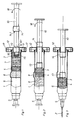
- the syringe for medical purposes shown in the drawing consists of a syringe cylinder 1, which is set up at one end for the attachment of an injection needle 2.
- a displaceable syringe plunger 3 and a stopper 4 which is arranged between the end of the needle hub 5 and the syringe plunger 3 and thus divides the interior of the syringe barrel 1 into two chambers 6, 7 of a two-chamber syringe.
- the outer surface of the syringe barrel 1 is provided with an axially extending cross-sectional widening forming a bypass 8.
- the two chambers 6, 7 are connected to one another via this by-pass 8 with the stopper 4 adjusted in the area of the by-pass 8.
- a damping part 9 is provided, which limits the adjustment speed of the piston rod 10.
- this damping part 9 is formed by a finger rest 12 which is placed on a glass bead 11 on the side of the syringe barrel 1 facing away from the end of the needle hub 5.
- the finger rest 12 is provided with an internal thread which is coaxial with the syringe cylinder 1 and which corresponds to a threaded shaft 13 arranged on the piston rod 10.
- the length of the threaded shaft 13 is so dimensioned that the screwing of this threaded shaft 13 through the internal thread of the plug 4 is adjusted in the area of the by-pass 8.
- the piston rod 10 has a second threaded shaft 14, which also corresponds to the internal thread of the finger rest 12.
- the two mutually facing end faces 13.1, 14.1 of the first and second threaded shafts 13, 14 each form a front or rear stop on the internal thread, thus allowing the piston rod 10 to move back and forth within the adjustment stroke defined by the two stops.
- the stops on both sides ensure on the one hand that the plug 4 cannot be pushed out on the area of the by-pass 8 and on the other hand ensure that the piston rod 10 with the syringe plunger 3 cannot be pulled out of the syringe barrel 1 by mistake.
- the syringe plunger 3 is retracted, the cannula 2 is placed on the end of the syringe tip 5, then the piston rod 10 is adjusted against the front stop 14.1 and then the second threaded shaft 14 is turned through the internal thread in the manner indicated by the arrow 18 whereupon the syringe is in the position shown in FIG. 3 and prepared for the application.
- the latter has a threaded shoulder 15 for a stopper thread provided in the syringe plunger 3, a cylindrical guide piece 16 being provided between the threaded shoulder 15 and the first threaded shaft 13, the diameter of which is only slightly smaller than the core diameter of the internal thread .
- the finger rest 12 is formed by two shell halves which receive the glass bead 11 of the syringe barrel 1 between them.
- the two shell halves are each provided with mutually engaging connecting elements 17, which are only indicated in the drawing, the shell half on the cannula side being provided with a recess surrounding the syringe barrel 1 and the other shell half being provided with the internal thread.
- This also makes it possible to attach the finger rest 12 to the pre-filled syringe only shortly before the preparation and use thereof.
- a further simplification of handling can be achieved in that the two shell halves are connected to one another in an articulated manner at the edge.
Landscapes
- Health & Medical Sciences (AREA)
- Vascular Medicine (AREA)
- Engineering & Computer Science (AREA)
- Anesthesiology (AREA)
- Biomedical Technology (AREA)
- Heart & Thoracic Surgery (AREA)
- Hematology (AREA)
- Life Sciences & Earth Sciences (AREA)
- Animal Behavior & Ethology (AREA)
- General Health & Medical Sciences (AREA)
- Public Health (AREA)
- Veterinary Medicine (AREA)
- Infusion, Injection, And Reservoir Apparatuses (AREA)
- Medicines Containing Material From Animals Or Micro-Organisms (AREA)
Claims (8)
- Procédé pour mélanger de façon intime une substance pharmaceutique introduite dans une seringue à deux chambres et dont la substance active est située, à l'état déshydraté dans une chambre (6) située du côté de l'aiguille, et dont le solvant est situé dans l'autre chambre (7), et dans lequel les deux chambres (6,7) sont séparées l'une de l'autre par un bouchon (4), qui, pour l'exécution du mélange intime de la substance avec le solvant, avant l'application, peut être amené dans la zone d'un by-pass (8) qui est prévu dans le cylindre (1) de la seringue et s'étend dans sa direction axiale et dont la longueur est supérieure à l'épaisseur axiale du bouchon (4), et dans lequel le bouchon (4) est déplacé, directement ou par l'intermédiaire du solvant, en direction de l'extrémité située du côté de l'aiguille, par l'intermédiaire du piston (3) de la seringue qui limite la seconde chambre (7) et est équipée d'une tige de piston (10), caractérisé en ce que, en position verticale alors que l'extrémité (5) de montage de l'aiguille est tournée vers le haut, on déplace tout d'abord le bouchon (4) à une vitesse limitée d'une manière conditionnée par le dispositif, en l'amenant dans la zone du by-pass (8), qu'on déplace ensuite le piston (3) de la seringue jusqu'à ce qu'il s'applique contre le bouchon (4), grâce à une libre mobilité de la tige de piston (10) jusqu'au niveau d'une butée avant (14.1) et que de ce fait le solvant est transféré dans la chambre (6) située du côté de l'aiguille, qu'ensuite, jusqu'à obtention de la dissolution complète de la substance, on rétracte à nouveau une ou plusieurs fois le piston (3) de la seringue jusqu'au niveau d'une butée arrière (13.1) de la tige de piston (10) et qu'ensuite à nouveau on le déplace jusqu'au niveau de la butée avant (14.1) de sorte que la substance active reflue à nouveau, ainsi que le solvant, depuis la chambre avant (6) dans la chambre arrière (7) en franchissant le by-pass (8), puis dans la chambre avant (6) et qu'enfin, après dissolution complète de la substance active, on desserre la butée avant (14') de la tige de piston (10), qui limite tout d'abord le déplacement du piston (3) de l'aiguille en direction de l'extrémité, située du côté de l'aiguille, du cylindre (1) de la seringue, pour l'application de la substance pharmaceutique.
- Procédé suivant la revendication 1, caractérisé par le fait qu'on installe la canule (2) lorsque la tige de piston (10) est déplacée jusqu'au niveau de la butée arrière (13.1).
- Seringue à usage médical pour la mise en oeuvre du procédé selon les revendications 1 et 2, comportant un cylindre (1) installé sur une extrémité prévue pour le montage d'une aiguille d'injection (2), et un piston (3) déplaçable dans le cylindre (1) de la seringue, ainsi qu'un bouchon (4), qui est disposé entre l'extrémité (5) de montage de l'aiguille et le piston (3) de la seringue et forme ainsi deux chambres (6,7) d'une seringue à deux chambres, et dans laquelle la surface enveloppe du cylindre (1) de la seringue comporte, dans la chambre (6) située du côté de l'aiguille, une partie élargie en coupe transversale, qui s'étend axialement et forme un by-pass (8) et au moyen de laquelle les deux chambres (6,7) sont réunies entre elles lorsque le bouchon est amené dans la zone (8) du by-pass (4), la seringue comportant également un élément d'amortissement (9) qui est utilisé comme frein pour le piston et est situé sur l'extrémité du cylindre tournée à l'opposé de l'extrémité (5) de montage de l'aiguille, caractérisée en ce que l'élément d'amortissement (9) limite la vitesse de déplacement de la tige de piston (10) jusqu'à ce que le bouchon (4) soit amené dans la zone du by-pass (8), et que la tige de piston (10) comporte, pour la limitation de la course de déplacement du piston (3) de la seringue entre sa position initiale contre l'extrémité du cylindre et sa position dans laquelle il est appliqué contre le bouchon (4) amené dans la zone du by-pass, une butée avant (14.1) et une butée arrière (13.1) pour un élément antagoniste prévu sur l'extrémité du cylindre, et que la butée avant (14.1), qui limite le déplacement du piston (3) de la seringue en direction de l'extrémité située du côté de l'aiguille, peut être desserrée.
- Seringue selon la revendication 3, caractérisée en ce que l'élément d'amortissement (9) est formé par un appui-doigt (12), qui est monté sur un rebord en verre (11) présent sur le côté du cylindre (1) de la seringue, tourné à l'opposé de l'extrémité (5) de montage de l'aiguille, et est pourvu d'un taraudage qui est coaxial au cylindre (1) de la seringue et est prévu pour un manchon fileté (13) installé sur la tige (10) du piston, le taraudage constituant l'élément antagoniste, tandis que la face frontale, tournée à l'opposé du cylindre de la seringue, forme la butée arrière et que la longueur du manchon fileté (13) est dimensionnée de manière que sa face frontale, tournée à l'opposé du piston (3) de la seringue, sort librement du taraudage dès que le bouchon (4) est situé dans la zone médiane du by-pass (8).
- Seringue selon la revendication 4, caractérisée en ce que la butée avant (14.1) est formée par la surface, tournée vers le premier manchon fileté (13), d'un second manchon fileté (14) qui correspond également au taraudage.
- Seringue selon la revendication 4 ou 5, caractérisée en ce que la tige de piston (10) possède frontalement un boit fileté (15) pour un filetage du bouchon prévu dans le piston (3) de la seringue, auquel cas entre le bout fileté (15) et le premier manchon fileté (13) il est prévu un élément cylindrique de guidage (16), dont le diamètre est seulement légèrement inférieur au diamètre de base du taraudage.
- Seringue selon les revendications 4 à 6, caractérisée en ce que l'appui-doigt (12) est formé par deux demi-coques, qui logent entre elles le rebord en verre (11) du cylindre (1) de la seringue et sont équipées d'éléments de liaison (17) qui s'encliquettent réciproquement, la demi-coque, située du côté de la canule, étant pourvue d'un logement qui entoure le cylindre (1) de la seringue, tandis que l'autre demi-coque est équipée du taraudage.
- Seringue selon la revendication 7, caractérisée en ce que les deux demi-coques sont raccordées entre elles d'une manière articulée au niveau de leurs bords.
Priority Applications (7)
| Application Number | Priority Date | Filing Date | Title |
|---|---|---|---|
| DE9090102373T DE59001705D1 (de) | 1990-02-07 | 1990-02-07 | Doppelkammerspritze und verwendungsverfahren. |
| EP90102373A EP0440846B1 (fr) | 1990-02-07 | 1990-02-07 | Seringue à chambre double et procédure d'emploi |
| AT90102373T ATE90211T1 (de) | 1990-02-07 | 1990-02-07 | Doppelkammerspritze und verwendungsverfahren. |
| ES199090102373T ES2042093T3 (es) | 1990-02-07 | 1990-02-07 | Jeringa de doble camara y procedimiento de empleo. |
| DK90102373.9T DK0440846T3 (da) | 1990-02-07 | 1990-02-07 | Dobbeltkammersprøjte og anvendelsesfremgangsmåde |
| US07/533,448 US5080649A (en) | 1990-02-07 | 1990-06-05 | Dual-compartment hypodermic syringe |
| JP3015297A JP2514472B2 (ja) | 1990-02-07 | 1991-02-06 | 二室注射器の中に充填した医薬物質の混合方法と、この方法の実施のための注射器 |
Applications Claiming Priority (1)
| Application Number | Priority Date | Filing Date | Title |
|---|---|---|---|
| EP90102373A EP0440846B1 (fr) | 1990-02-07 | 1990-02-07 | Seringue à chambre double et procédure d'emploi |
Publications (2)
| Publication Number | Publication Date |
|---|---|
| EP0440846A1 EP0440846A1 (fr) | 1991-08-14 |
| EP0440846B1 true EP0440846B1 (fr) | 1993-06-09 |
Family
ID=8203602
Family Applications (1)
| Application Number | Title | Priority Date | Filing Date |
|---|---|---|---|
| EP90102373A Expired - Lifetime EP0440846B1 (fr) | 1990-02-07 | 1990-02-07 | Seringue à chambre double et procédure d'emploi |
Country Status (7)
| Country | Link |
|---|---|
| US (1) | US5080649A (fr) |
| EP (1) | EP0440846B1 (fr) |
| JP (1) | JP2514472B2 (fr) |
| AT (1) | ATE90211T1 (fr) |
| DE (1) | DE59001705D1 (fr) |
| DK (1) | DK0440846T3 (fr) |
| ES (1) | ES2042093T3 (fr) |
Cited By (3)
| Publication number | Priority date | Publication date | Assignee | Title |
|---|---|---|---|---|
| US5728075A (en) * | 1993-10-29 | 1998-03-17 | Pharmacia & Upjohn Aktiebolag | Injection devices |
| EP0830868A2 (fr) * | 1996-09-23 | 1998-03-25 | Arzneimittel GmbH Apotheker Vetter & Co. Ravensburg | Seringue préremplie pour but médical |
| US7998106B2 (en) | 2004-05-03 | 2011-08-16 | Thorne Jr Gale H | Safety dispensing system for hazardous substances |
Families Citing this family (130)
| Publication number | Priority date | Publication date | Assignee | Title |
|---|---|---|---|---|
| US6540154B1 (en) * | 1991-04-24 | 2003-04-01 | Aerogen, Inc. | Systems and methods for controlling fluid feed to an aerosol generator |
| JPH0531190A (ja) * | 1991-07-26 | 1993-02-09 | Seikagaku Kogyo Co Ltd | 注射具 |
| US5211285A (en) * | 1992-03-19 | 1993-05-18 | Habley Medical Technology Corporation | Telescoping, pharmaceutical mixing container |
| IL105396A (en) * | 1992-04-30 | 1998-02-22 | Takeda Chemical Industries Ltd | Pre-filled syringe |
| JP3471318B2 (ja) * | 1992-11-27 | 2003-12-02 | 株式会社大協精工 | 注射器兼容器 |
| US5364386A (en) * | 1993-05-05 | 1994-11-15 | Hikari Seiyaku Kabushiki Kaisha | Infusion unit |
| SE9303453D0 (sv) * | 1993-10-20 | 1993-10-20 | Kabi Pharmacia Ab | Injection cartridge |
| US5586975A (en) * | 1994-02-18 | 1996-12-24 | Takeda Chemical Industries. Ltd. | Air and liquid tight container with a slidable gasket |
| US6782886B2 (en) | 1995-04-05 | 2004-08-31 | Aerogen, Inc. | Metering pumps for an aerosolizer |
| US6205999B1 (en) * | 1995-04-05 | 2001-03-27 | Aerogen, Inc. | Methods and apparatus for storing chemical compounds in a portable inhaler |
| US5758637A (en) | 1995-08-31 | 1998-06-02 | Aerogen, Inc. | Liquid dispensing apparatus and methods |
| WO1998001174A1 (fr) * | 1996-07-05 | 1998-01-15 | Debiotech S.A. | Seringue a chambre double permettant le melange de deux produits avant leur injection |
| JP3949752B2 (ja) * | 1996-07-29 | 2007-07-25 | 日本ケミカルリサーチ株式会社 | 薬剤溶解機構付注射器 |
| US5865804A (en) * | 1997-07-16 | 1999-02-02 | Bachynsky; Nicholas | Rotary cam syringe |
| US5971953A (en) * | 1998-01-09 | 1999-10-26 | Bachynsky; Nicholas | Dual chamber syringe apparatus |
| US6149626A (en) * | 1997-10-03 | 2000-11-21 | Bachynsky; Nicholas | Automatic injecting syringe apparatus |
| US6681475B2 (en) | 1998-04-20 | 2004-01-27 | Becton Dickinson And Company | Method of sealing a medical container with a plastic closure |
| US6378714B1 (en) | 1998-04-20 | 2002-04-30 | Becton Dickinson And Company | Transferset for vials and other medical containers |
| DE19821933C1 (de) * | 1998-05-15 | 1999-11-11 | Disetronic Licensing Ag | Vorrichtung zur Verabreichung eines injizierbaren Produkts |
| US6907679B2 (en) * | 1998-11-12 | 2005-06-21 | Qlt Usa, Inc. | Method for lyophilizing an active agent |
| DE19912322A1 (de) * | 1999-03-19 | 2000-09-28 | Vetter & Co Apotheker | Spritze für medizinische Zwecke |
| SE9901366D0 (sv) * | 1999-04-16 | 1999-04-16 | Pharmacia & Upjohn Ab | Injector device and method for its operation |
| US6331173B1 (en) | 1999-04-20 | 2001-12-18 | Pharmacia Ab | Device for displacing a member in a container |
| US6235177B1 (en) | 1999-09-09 | 2001-05-22 | Aerogen, Inc. | Method for the construction of an aperture plate for dispensing liquid droplets |
| JP2003527159A (ja) | 1999-10-22 | 2003-09-16 | アンタレス・ファーマ・インコーポレーテッド | 薬剤カートリッジ及び注射装置 |
| CN100341483C (zh) * | 2000-02-28 | 2007-10-10 | 维克丘拉有限公司 | 口服药物输递中或涉及口服药物输递的改进 |
| FR2806916B1 (fr) * | 2000-03-31 | 2002-11-29 | Sedat | Seringue d'injection d'un melange extemporane |
| US7600511B2 (en) * | 2001-11-01 | 2009-10-13 | Novartis Pharma Ag | Apparatus and methods for delivery of medicament to a respiratory system |
| US8336545B2 (en) * | 2000-05-05 | 2012-12-25 | Novartis Pharma Ag | Methods and systems for operating an aerosol generator |
| US7100600B2 (en) | 2001-03-20 | 2006-09-05 | Aerogen, Inc. | Fluid filled ampoules and methods for their use in aerosolizers |
| US6948491B2 (en) | 2001-03-20 | 2005-09-27 | Aerogen, Inc. | Convertible fluid feed system with comformable reservoir and methods |
| MXPA02010884A (es) * | 2000-05-05 | 2003-03-27 | Aerogen Ireland Ltd | Aparato y metodo para el suministro de medicamentos al sistema respiratorio. |
| US7971588B2 (en) * | 2000-05-05 | 2011-07-05 | Novartis Ag | Methods and systems for operating an aerosol generator |
| AU2001275393A1 (en) | 2000-06-08 | 2001-12-17 | Meridian Medical Technologies, Inc. | Wet/dry automatic injector assembly |
| US6543443B1 (en) | 2000-07-12 | 2003-04-08 | Aerogen, Inc. | Methods and devices for nebulizing fluids |
| DE10036594A1 (de) * | 2000-07-27 | 2002-02-07 | Pfeiffer Erich Gmbh & Co Kg | Austragvorrichtung für Medien |
| US7621887B2 (en) * | 2000-10-10 | 2009-11-24 | Meridian Medical Technologies, Inc. | Wet/dry automatic injector assembly |
| US6641561B1 (en) | 2000-10-10 | 2003-11-04 | Meridian Medical Technologies, Inc. | Drug delivery device |
| US7544189B2 (en) * | 2000-10-10 | 2009-06-09 | Meridian Medical Technologies, Inc. | Needle and hub assembly for automatic injector |
| US7556614B2 (en) * | 2000-10-10 | 2009-07-07 | Meridian Medical Technologies, Inc. | Separation assembly for drug delivery device |
| US6656150B2 (en) * | 2000-10-10 | 2003-12-02 | Meridian Medical Technologies, Inc. | Wet/dry automatic injector assembly |
| US6546927B2 (en) | 2001-03-13 | 2003-04-15 | Aerogen, Inc. | Methods and apparatus for controlling piezoelectric vibration |
| US6550472B2 (en) | 2001-03-16 | 2003-04-22 | Aerogen, Inc. | Devices and methods for nebulizing fluids using flow directors |
| US6732944B2 (en) | 2001-05-02 | 2004-05-11 | Aerogen, Inc. | Base isolated nebulizing device and methods |
| US6554201B2 (en) | 2001-05-02 | 2003-04-29 | Aerogen, Inc. | Insert molded aerosol generator and methods |
| DE10140704A1 (de) * | 2001-08-18 | 2003-03-06 | Vetter & Co Apotheker | Verfahren zur Durchmischung einer schwer löslichen pharmazeutischen Substanz mit einem Lösungsmittel und Spritze zur Anwendung des Verfahrens |
| US20050205089A1 (en) * | 2002-01-07 | 2005-09-22 | Aerogen, Inc. | Methods and devices for aerosolizing medicament |
| US7360536B2 (en) | 2002-01-07 | 2008-04-22 | Aerogen, Inc. | Devices and methods for nebulizing fluids for inhalation |
| US7677467B2 (en) * | 2002-01-07 | 2010-03-16 | Novartis Pharma Ag | Methods and devices for aerosolizing medicament |
| AU2003203043A1 (en) * | 2002-01-15 | 2003-07-30 | Aerogen, Inc. | Methods and systems for operating an aerosol generator |
| ES2314182T3 (es) | 2002-02-11 | 2009-03-16 | Antares Pharma, Inc. | Inyector intradermico. |
| EP1476211B1 (fr) * | 2002-02-15 | 2015-06-24 | Antares Pharma, Inc. | Injecteur avec canal de derivation |
| US20070044792A1 (en) * | 2005-08-30 | 2007-03-01 | Aerogen, Inc. | Aerosol generators with enhanced corrosion resistance |
| US6915962B2 (en) * | 2002-05-20 | 2005-07-12 | Aerogen, Inc. | Apparatus for providing aerosol for medical treatment and methods |
| DE10254321A1 (de) * | 2002-11-21 | 2004-06-17 | Arzneimittel Gmbh Apotheker Vetter & Co. Ravensburg | Vorgefüllte Spritze |
| US7678333B2 (en) * | 2003-01-22 | 2010-03-16 | Duoject Medical Systems Inc. | Fluid transfer assembly for pharmaceutical delivery system and method for using same |
| ATE465709T1 (de) * | 2003-01-22 | 2010-05-15 | Duoject Inc | Pharmazeutische abgabesysteme |
| US7699804B2 (en) * | 2003-01-31 | 2010-04-20 | Creare Inc. | Fluid ejection system |
| US8616195B2 (en) * | 2003-07-18 | 2013-12-31 | Novartis Ag | Nebuliser for the production of aerosolized medication |
| EP1756162A1 (fr) | 2004-03-23 | 2007-02-28 | Biogen Idec MA Inc. | Agents de couplage recepteurs et leurs applications therapeutiques |
| US7290541B2 (en) * | 2004-04-20 | 2007-11-06 | Aerogen, Inc. | Aerosol delivery apparatus and method for pressure-assisted breathing systems |
| US7946291B2 (en) | 2004-04-20 | 2011-05-24 | Novartis Ag | Ventilation systems and methods employing aerosol generators |
| US7267121B2 (en) * | 2004-04-20 | 2007-09-11 | Aerogen, Inc. | Aerosol delivery apparatus and method for pressure-assisted breathing systems |
| EP1740242A4 (fr) * | 2004-04-20 | 2009-12-23 | Aerogen Inc | Appareil d'administration en aerosol, methodes et compositions pour systemes de respiration assistee en pression |
| US6997910B2 (en) * | 2004-05-03 | 2006-02-14 | Infusive Technologies, Llc | Multi-chamber, sequential dose dispensing syringe |
| US7101354B2 (en) | 2004-05-03 | 2006-09-05 | Infusive Technologies, Llc | Mixing syringe with and without flush |
| US7731678B2 (en) * | 2004-10-13 | 2010-06-08 | Hyprotek, Inc. | Syringe devices and methods for mixing and administering medication |
| DE102004056617A1 (de) | 2004-11-24 | 2006-06-01 | Arthur Fabian | Medizinische Doppelkammer-Spritze aus Kunststoff |
| CA2588888A1 (fr) * | 2004-12-03 | 2006-06-08 | Duoject Medical Systems Inc. | Cartouche, dispositif et procede de stockage, melangeage et delivrance de constituants pharmaceutiques |
| US20060157507A1 (en) * | 2004-12-30 | 2006-07-20 | Chang Byeong S | Multi-functional container closure delivery system |
| US7959600B2 (en) * | 2004-12-30 | 2011-06-14 | Byeong S. Chang | Container closure delivery system |
| US20060144869A1 (en) * | 2004-12-30 | 2006-07-06 | Chang Byeong S | Container closure delivery system |
| BRPI0614025A2 (pt) | 2005-01-24 | 2012-12-25 | Antares Pharma Inc | injetores de jato |
| AU2006210865B2 (en) | 2005-02-01 | 2008-12-04 | Kaleo, Inc. | Devices, systems, and methods for medicament delivery |
| JP2008540039A (ja) * | 2005-05-16 | 2008-11-20 | マリンクロッド・インコーポレイテッド | マルチステージ注射器、およびこれを使用する方法 |
| UA94711C2 (uk) * | 2005-05-25 | 2011-06-10 | Аэроджен, Инк. | Вібраційна система (варіанти) та спосіб її виготовлення (варіанти), спосіб вібрування пластини (варіанти), система виробництва аерозолю та спосіб лікування пацієнта |
| CA2626864C (fr) | 2005-11-09 | 2015-06-02 | Hyprotek, Inc. | Dispositifs de type seringue, leurs elements constitutifs et procedes de formation d'un agent medicamenteux dans lesdits dispositifs |
| JP4834389B2 (ja) * | 2005-11-29 | 2011-12-14 | 前田産業株式会社 | 注射装置 |
| WO2007131013A1 (fr) | 2006-05-03 | 2007-11-15 | Antares Pharma, Inc. | Injecteur de reconstitution à deux étages |
| EP1894590B1 (fr) * | 2006-08-30 | 2012-04-25 | Roche Diagnostics GmbH | Dispositif d'injection avec simplification de la retenue d'un bouchon |
| FR2905682B1 (fr) * | 2006-09-13 | 2011-05-20 | Becton Dickinson France | Recipient, dispositif medical et procede pour contenir et expulser un produit. |
| BRPI0808709A2 (pt) * | 2007-03-09 | 2014-09-09 | Lilly Co Eli | Mecanismo de atrso para dispositivo de injeção automático |
| US9522097B2 (en) | 2007-10-04 | 2016-12-20 | Hyprotek, Inc. | Mixing/administration syringe devices, protective packaging and methods of protecting syringe handlers |
| US8002737B2 (en) | 2007-10-04 | 2011-08-23 | Hyprotek, Inc. | Mixing/administration syringe devices, protective packaging and methods of protecting syringe handlers |
| NZ584679A (en) * | 2007-11-22 | 2012-09-28 | Biovitrum Ab Publ | A method and device for the serial ejection of two fluids comprising a spacer to retain a volume of a second fluid for rinsing |
| CN101939088B (zh) * | 2008-02-28 | 2013-05-08 | 药物混合系统股份公司 | 用于吸入和分配组分的单腔装置 |
| DE102008030267B3 (de) | 2008-06-19 | 2010-01-28 | Arzneimittel Gmbh Apotheker Vetter & Co. Ravensburg | Verfahren zum Befüllen von Doppelkammersystemen in vorsterilisierbaren Trägersystemen und vorsterilisierbares Trägersystem |
| DE102008030268B3 (de) * | 2008-06-19 | 2010-02-04 | Arzneimittel Gmbh Apotheker Vetter & Co. Ravensburg | Verfahren zum Befüllen von Doppelkammersystemen in vorsterilisierbaren Trägersystemen und vorsterilisierbares Trägersystem |
| EP3581224A1 (fr) | 2008-08-05 | 2019-12-18 | Antares Pharma, Inc. | Injecteur à dosage multiple |
| US9061107B2 (en) * | 2008-09-18 | 2015-06-23 | Becton, Dickinson and Comapany | Needle mounting feature for ensuring proper reconstitution sequence |
| US8579865B2 (en) | 2009-03-20 | 2013-11-12 | Antares Pharma, Inc. | Hazardous agent injection system |
| US20100274185A1 (en) * | 2009-04-28 | 2010-10-28 | Thomas Chun | Automatic injection syringe assembly |
| JP2012525236A (ja) * | 2009-04-30 | 2012-10-22 | ハイパーブランチ メディカル テクノロジー, インコーポレイテッド | 外科手術用封止剤のための内蔵型医学的適用およびその使用方法 |
| US20100324480A1 (en) * | 2009-06-17 | 2010-12-23 | Thomas Chun | Automatic injection syringe assembly |
| DK2708252T3 (en) | 2010-03-01 | 2015-11-02 | Lilly Co Eli | Automatic injection device with delay mechanism including double acting biasing element |
| AU2011229797B2 (en) | 2010-03-23 | 2017-02-16 | Hyperbranch Medical Technology, Inc. | Disposable syringe applicators for multi-component formulations, and methods of use thereof |
| GB2482248B (en) * | 2010-07-22 | 2013-05-22 | Kevin Abbott | Fluid dose dispensing apparatus |
| JP4757951B1 (ja) * | 2010-10-19 | 2011-08-24 | 株式会社アルテ | 二室式容器兼用注射器 |
| AR083884A1 (es) * | 2010-11-16 | 2013-03-27 | Otsuka Pharma Co Ltd | Jeringa prellenable de doble camara y relleno de aripiprazol en la jeringa |
| EP2663275B1 (fr) | 2011-01-10 | 2017-03-08 | Byeong Seon Chang | Dispositif et procédé de reconstitution de médicament compact |
| US9084849B2 (en) | 2011-01-26 | 2015-07-21 | Kaleo, Inc. | Medicament delivery devices for administration of a medicament within a prefilled syringe |
| US10092688B2 (en) | 2011-05-13 | 2018-10-09 | Laura Jean Robinson | Medicament kit and method of use |
| US8496619B2 (en) | 2011-07-15 | 2013-07-30 | Antares Pharma, Inc. | Injection device with cammed ram assembly |
| US9220660B2 (en) | 2011-07-15 | 2015-12-29 | Antares Pharma, Inc. | Liquid-transfer adapter beveled spike |
| WO2013152323A1 (fr) | 2012-04-06 | 2013-10-10 | Wotton Paul K | Administration par injection par jet assistée par une aiguille de compositions de testostérone |
| US9364611B2 (en) | 2012-05-07 | 2016-06-14 | Antares Pharma, Inc. | Needle assisted jet injection device having reduced trigger force |
| US9522235B2 (en) | 2012-05-22 | 2016-12-20 | Kaleo, Inc. | Devices and methods for delivering medicaments from a multi-chamber container |
| US9731076B2 (en) * | 2012-06-29 | 2017-08-15 | Ethicon, Inc. | Multi-compartment pre-filled mixing syringes with bypass |
| WO2014124427A1 (fr) | 2013-02-11 | 2014-08-14 | Travanty Michael | Dispositif d'injection par jet assisté par aiguille disposant d'une force de déclenchement réduite |
| ES2742046T3 (es) | 2013-03-11 | 2020-02-12 | Antares Pharma Inc | Inyector de dosis con sistema de piñón |
| KR20150119079A (ko) | 2013-03-14 | 2015-10-23 | 일라이 릴리 앤드 캄파니 | 자동 주사 장치를 위한 트리거 조립체 |
| ES2927108T3 (es) | 2013-03-14 | 2022-11-02 | Lilly Co Eli | Mecanismo de retardo adecuado para dispositivo de inyección automática compacto |
| US10952709B2 (en) | 2014-04-04 | 2021-03-23 | Hyperbranch Medical Technology, Inc. | Extended tip spray applicator for two-component surgical sealant, and methods of use thereof |
| MX2017003095A (es) | 2014-09-09 | 2018-01-26 | Seon Chang Byeong | Dispositivo y método de entrega de solución. |
| JP7032135B2 (ja) | 2014-12-30 | 2022-03-08 | キンデーバ ドラッグ デリバリー リミティド パートナーシップ | 2つの構成成分を混合し分注するための容器 |
| WO2016109339A1 (fr) | 2014-12-30 | 2016-07-07 | 3M Innovative Properties Company | Récipient pour mélanger et distribuer des composants de médicament liquides |
| JP6985142B2 (ja) | 2014-12-30 | 2021-12-22 | キンデーバ ドラッグ デリバリー リミティド パートナーシップ | 構成成分を混合及び分注するための容器 |
| AU2016235054B2 (en) | 2015-03-24 | 2020-07-16 | Kaleo, Inc. | Devices and methods for delivering a lyophilized medicament |
| JP6830067B2 (ja) | 2015-06-30 | 2021-02-17 | カレオ,インコーポレイテッド | プレフィルドシリンジ内の医薬を投与する自動注射器 |
| CH711656A2 (de) * | 2015-10-19 | 2017-04-28 | Tecpharma Licensing Ag | Vorrichtung zur Verabreichung eines Wirkstoffs und Verfahren zur Bedienung dieser Vorrichtung. |
| CH711655A2 (de) * | 2015-10-19 | 2017-04-28 | Tecpharma Licensing Ag | Vorrichtung zur Verabreichung eines Wirkstoffs und Verfahren zur Bedienung dieser Vorrichtung. |
| CH711657A2 (de) * | 2015-10-19 | 2017-04-28 | Tecpharma Licensing Ag | Vorrichtung zur Verabreichung eines Wirkstoffs und Verfahren zur Bedienung dieser Vorrichtung. |
| UA122170C2 (uk) | 2016-02-05 | 2020-09-25 | Толмар Терапьютікс, Інк. | Вентильована покривна пластина для масиву шприців |
| FR3050984B1 (fr) * | 2016-05-04 | 2020-05-15 | Aptar France Sas | Dispositif de distribution de produit fluide. |
| WO2017191641A1 (fr) * | 2016-05-04 | 2017-11-09 | Zelikman, Zarema | Appareil de mélange et procédé associé |
| FR3055807B1 (fr) | 2016-09-15 | 2019-08-16 | Edix Sa | Dispositif connecteur-seringue pour administrer separement au moins deux produits en quantites controlees et en une seule injection |
| US11547797B2 (en) * | 2017-07-17 | 2023-01-10 | Baxter International Inc. | Medical syringe system with filtered filling port |
| USD908916S1 (en) | 2018-06-19 | 2021-01-26 | Tolmar Therapeutics, Inc. | Syringe restrictor plate |
| CA3145580A1 (fr) | 2019-08-09 | 2021-02-18 | Kaleo, Inc. | Dispositifs et procedes de distribution de substances dans une seringue pre-remplie |
| CN110960268B (zh) * | 2020-01-06 | 2023-04-21 | 北京新希望六和生物科技产业集团有限公司 | 一种畜用组织微创采样器 |
Family Cites Families (15)
| Publication number | Priority date | Publication date | Assignee | Title |
|---|---|---|---|---|
| US2591046A (en) * | 1948-10-18 | 1952-04-01 | Frederick M Turnbull | Hypodermic syringe assembly |
| US2549417A (en) * | 1949-08-10 | 1951-04-17 | Frederick M Turnbull | Syringe ampoule |
| GB1214053A (en) * | 1968-02-05 | 1970-12-02 | Hans Wimmer | Improvements in or relating to two chamber injection ampoules |
| JPS55116620U (fr) * | 1979-02-13 | 1980-08-18 | ||
| US4226236A (en) * | 1979-05-07 | 1980-10-07 | Abbott Laboratories | Prefilled, vented two-compartment syringe |
| US4312343A (en) * | 1979-07-30 | 1982-01-26 | Leveen Harry H | Syringe |
| US4583974A (en) * | 1984-04-04 | 1986-04-22 | Kokernak Denis T | Syringe for balloon dilation catheters |
| US4599082A (en) * | 1984-08-13 | 1986-07-08 | Becton, Dickinson And Company | Two-component syringe assembly |
| DE3687530T2 (de) * | 1985-06-27 | 1993-07-22 | Duphar Int Res | Spritze. |
| US4613326A (en) * | 1985-07-12 | 1986-09-23 | Becton, Dickinson And Company | Two-component medication syringe assembly |
| EP0295337B1 (fr) * | 1987-06-16 | 1991-12-04 | Akzo Nobel N.V. | Seringe à deux compartiments et procédé de fabrication |
| IL86799A (en) * | 1987-07-02 | 1993-03-15 | Kabi Pharmacia Ab | Method and device for injection |
| GB8723454D0 (en) * | 1987-10-06 | 1987-11-11 | Beecham Group Plc | Device |
| ES2024564B3 (es) * | 1988-02-16 | 1992-03-01 | Arzneimittel Gmbh Apotheker Vetter & Co Ravensburg | Jeringuilla con fines medicinales |
| FR2634650B1 (fr) * | 1988-08-01 | 1990-11-02 | Labouze Joseph | Seringue non reutilisable |
-
1990
- 1990-02-07 EP EP90102373A patent/EP0440846B1/fr not_active Expired - Lifetime
- 1990-02-07 DE DE9090102373T patent/DE59001705D1/de not_active Expired - Lifetime
- 1990-02-07 AT AT90102373T patent/ATE90211T1/de not_active IP Right Cessation
- 1990-02-07 DK DK90102373.9T patent/DK0440846T3/da active
- 1990-02-07 ES ES199090102373T patent/ES2042093T3/es not_active Expired - Lifetime
- 1990-06-05 US US07/533,448 patent/US5080649A/en not_active Expired - Lifetime
-
1991
- 1991-02-06 JP JP3015297A patent/JP2514472B2/ja not_active Expired - Lifetime
Cited By (4)
| Publication number | Priority date | Publication date | Assignee | Title |
|---|---|---|---|---|
| US5728075A (en) * | 1993-10-29 | 1998-03-17 | Pharmacia & Upjohn Aktiebolag | Injection devices |
| EP0830868A2 (fr) * | 1996-09-23 | 1998-03-25 | Arzneimittel GmbH Apotheker Vetter & Co. Ravensburg | Seringue préremplie pour but médical |
| US5833653A (en) * | 1996-09-23 | 1998-11-10 | Arzneimittel Gmbh Apotheker Vetter & Co. Ravensburg | Prefilled hypodermic syringe |
| US7998106B2 (en) | 2004-05-03 | 2011-08-16 | Thorne Jr Gale H | Safety dispensing system for hazardous substances |
Also Published As
| Publication number | Publication date |
|---|---|
| US5080649A (en) | 1992-01-14 |
| ATE90211T1 (de) | 1993-06-15 |
| JPH04322662A (ja) | 1992-11-12 |
| EP0440846A1 (fr) | 1991-08-14 |
| DK0440846T3 (da) | 1993-07-12 |
| DE59001705D1 (de) | 1993-07-15 |
| JP2514472B2 (ja) | 1996-07-10 |
| ES2042093T3 (es) | 1993-12-01 |
Similar Documents
| Publication | Publication Date | Title |
|---|---|---|
| EP0440846B1 (fr) | Seringue à chambre double et procédure d'emploi | |
| DE69319495T2 (de) | Vorgefüllte Spritze | |
| EP0328699B1 (fr) | Seringue à usage médical | |
| DE69326601T2 (de) | Injektionsbehälter mit zwei kammern | |
| EP1287841B1 (fr) | Procédé pour mélanger une substance pharmaceutique peu soluble avec un solvant et seringue pour la mise en oeuvre de ce procédé | |
| DE69623268T2 (de) | Vorgefüllte spritze zur verabreichung von medikamenten | |
| DE69603652T2 (de) | Verfahren zur Herstellung einer vorgefüllten Injektionsvorrichtung und dadurch erhaltene Injektionsvorrichtung | |
| DE69301448T2 (de) | Injektionsvorrichtung | |
| DE69628275T2 (de) | Gerät zum Transferieren von Flüssigkeiten von einem Arzneiflakon zu einer Spritze | |
| DE68906278T2 (de) | Einziehbare einwegspritze. | |
| DE3823266C2 (de) | Spritzampulle | |
| DE69726531T2 (de) | Verriegelbare Schutzhülse für vorgefüllte Spritze | |
| DE68902781T2 (de) | Sicherheits-wegwerfspritze. | |
| DE69320802T2 (de) | Injektionsbehälter | |
| DE69009777T2 (de) | Sichere einwegspritze mit zurückziehender nadel und einrichtung zur verhinderung von wiedergebrauch. | |
| DE69527281T2 (de) | Nachrüstsatz für eine automatische intravaskuläre lösungseinspritzmaschine | |
| DE2046953A1 (de) | Durch die Verschlußoffnung gefüllte Spritze und Verfahren zu ihrer Füllung | |
| DE1195907B (de) | Nadellose Injektionsspritze | |
| EP0652019A1 (fr) | Seringue pour le mélange et l'administration de produits injectables | |
| DE2909002B2 (de) | Injektionsspritze für einmalige Verwendung | |
| CH712753A2 (de) | Trennen einer Nadelschutzkappe von einem Produktbehälter und Verfahren zum Montieren einer Injektionsvorrichtung. | |
| DE19935681A1 (de) | Vorrichtung zum Befüllen eines Spritzenzylinders und/oder zum Setzen eines Stopfens im Spritzenzylinder | |
| EP1186312A2 (fr) | Dispositif distributeur de substances | |
| DE2701903A1 (de) | Medikamentzusatzsystem | |
| DE4120267A1 (de) | Verfahren zum betrieb einer vorrichtung zur abgabe eines fluessigen medizinischen behandlungsstoffes an einen zu behandelnden koerper und vorrichtung zur durchfuehrung des verfahrens |
Legal Events
| Date | Code | Title | Description |
|---|---|---|---|
| PUAI | Public reference made under article 153(3) epc to a published international application that has entered the european phase |
Free format text: ORIGINAL CODE: 0009012 |
|
| 17P | Request for examination filed |
Effective date: 19901116 |
|
| AK | Designated contracting states |
Kind code of ref document: A1 Designated state(s): AT BE CH DE DK ES FR GB GR IT LI LU NL SE |
|
| 17Q | First examination report despatched |
Effective date: 19921201 |
|
| GRAA | (expected) grant |
Free format text: ORIGINAL CODE: 0009210 |
|
| AK | Designated contracting states |
Kind code of ref document: B1 Designated state(s): AT BE CH DE DK ES FR GB GR IT LI LU NL SE |
|
| REF | Corresponds to: |
Ref document number: 90211 Country of ref document: AT Date of ref document: 19930615 Kind code of ref document: T |
|
| ITF | It: translation for a ep patent filed | ||
| REG | Reference to a national code |
Ref country code: DK Ref legal event code: T3 |
|
| REF | Corresponds to: |
Ref document number: 59001705 Country of ref document: DE Date of ref document: 19930715 |
|
| ET | Fr: translation filed | ||
| REG | Reference to a national code |
Ref country code: GR Ref legal event code: FG4A Free format text: 3008324 |
|
| GBT | Gb: translation of ep patent filed (gb section 77(6)(a)/1977) |
Effective date: 19930816 |
|
| REG | Reference to a national code |
Ref country code: ES Ref legal event code: FG2A Ref document number: 2042093 Country of ref document: ES Kind code of ref document: T3 |
|
| EPTA | Lu: last paid annual fee | ||
| PLBE | No opposition filed within time limit |
Free format text: ORIGINAL CODE: 0009261 |
|
| STAA | Information on the status of an ep patent application or granted ep patent |
Free format text: STATUS: NO OPPOSITION FILED WITHIN TIME LIMIT |
|
| 26N | No opposition filed | ||
| EAL | Se: european patent in force in sweden |
Ref document number: 90102373.9 |
|
| REG | Reference to a national code |
Ref country code: GB Ref legal event code: IF02 |
|
| PGFP | Annual fee paid to national office [announced via postgrant information from national office to epo] |
Ref country code: LU Payment date: 20090206 Year of fee payment: 20 Ref country code: AT Payment date: 20090228 Year of fee payment: 20 Ref country code: FR Payment date: 20081113 Year of fee payment: 20 Ref country code: ES Payment date: 20090109 Year of fee payment: 20 Ref country code: DK Payment date: 20090206 Year of fee payment: 20 |
|
| PGFP | Annual fee paid to national office [announced via postgrant information from national office to epo] |
Ref country code: NL Payment date: 20090227 Year of fee payment: 20 |
|
| PGFP | Annual fee paid to national office [announced via postgrant information from national office to epo] |
Ref country code: GR Payment date: 20081111 Year of fee payment: 20 Ref country code: CH Payment date: 20090218 Year of fee payment: 20 Ref country code: GB Payment date: 20081230 Year of fee payment: 20 |
|
| PGFP | Annual fee paid to national office [announced via postgrant information from national office to epo] |
Ref country code: BE Payment date: 20090227 Year of fee payment: 20 |
|
| PGFP | Annual fee paid to national office [announced via postgrant information from national office to epo] |
Ref country code: SE Payment date: 20090213 Year of fee payment: 20 Ref country code: DE Payment date: 20090414 Year of fee payment: 20 Ref country code: IT Payment date: 20090226 Year of fee payment: 20 |
|
| REG | Reference to a national code |
Ref country code: CH Ref legal event code: PL |
|
| REG | Reference to a national code |
Ref country code: DK Ref legal event code: EUP |
|
| BE20 | Be: patent expired |
Owner name: *ARZNEIMITTEL G.M.B.H. APOTHEKER VETTER & CO. RAVE Effective date: 20100207 |
|
| REG | Reference to a national code |
Ref country code: GB Ref legal event code: PE20 Expiry date: 20100206 |
|
| NLV7 | Nl: ceased due to reaching the maximum lifetime of a patent |
Effective date: 20100207 |
|
| REG | Reference to a national code |
Ref country code: ES Ref legal event code: FD2A Effective date: 20100208 |
|
| PG25 | Lapsed in a contracting state [announced via postgrant information from national office to epo] |
Ref country code: GB Free format text: LAPSE BECAUSE OF EXPIRATION OF PROTECTION Effective date: 20100206 |
|
| PG25 | Lapsed in a contracting state [announced via postgrant information from national office to epo] |
Ref country code: ES Free format text: LAPSE BECAUSE OF EXPIRATION OF PROTECTION Effective date: 20100208 |
|
| PG25 | Lapsed in a contracting state [announced via postgrant information from national office to epo] |
Ref country code: DE Free format text: LAPSE BECAUSE OF EXPIRATION OF PROTECTION Effective date: 20100207 |