EP0437757A2 - Dispositif appliqué à la surveillance de passage de personnes dans un corridor - Google Patents
Dispositif appliqué à la surveillance de passage de personnes dans un corridor Download PDFInfo
- Publication number
- EP0437757A2 EP0437757A2 EP90124363A EP90124363A EP0437757A2 EP 0437757 A2 EP0437757 A2 EP 0437757A2 EP 90124363 A EP90124363 A EP 90124363A EP 90124363 A EP90124363 A EP 90124363A EP 0437757 A2 EP0437757 A2 EP 0437757A2
- Authority
- EP
- European Patent Office
- Prior art keywords
- corridor
- passage
- signals
- signal
- evaluation
- Prior art date
- Legal status (The legal status is an assumption and is not a legal conclusion. Google has not performed a legal analysis and makes no representation as to the accuracy of the status listed.)
- Granted
Links
Images
Classifications
-
- G—PHYSICS
- G07—CHECKING-DEVICES
- G07C—TIME OR ATTENDANCE REGISTERS; REGISTERING OR INDICATING THE WORKING OF MACHINES; GENERATING RANDOM NUMBERS; VOTING OR LOTTERY APPARATUS; ARRANGEMENTS, SYSTEMS OR APPARATUS FOR CHECKING NOT PROVIDED FOR ELSEWHERE
- G07C9/00—Individual registration on entry or exit
Definitions
- the invention relates to a device for monitoring a corridor according to the preamble of claim 1.
- a device for determining the number of people (separation) within a room to be monitored or a so-called lock is already known (DE-PS 36 23 792), in which IR sensors, so-called passive IR sensors ( in the following PIR sensor), a sensor field is generated which, as a singling criterion, generates a release or blocking signal to an access control unit by detecting moving bodies in an evaluation unit.
- This known device requires at least two of these PIR sensors, the signals of which are fed to the evaluation unit, taking into account the sensor distance, in order to determine the number of people passing through the lock.
- the functionality of these PIR sensors is based on the determination of the deviation of the ambient temperature from the body heat of the people passing through and on the recording of the time course of this deviation depending on the speed of the person and the energy of the infrared radiation.
- the at least two PIR sensors must be arranged one behind the other in the direction of passage. To monitor a larger passage width, at least two sensors in the transverse direction are also required in each case.
- Devices of this type are complex not only because of the large number of PIR sensors required, but in particular also because of the complicated electronic evaluation unit required for evaluating the analog signals supplied by the PIR sensors, which, precisely because of their complexity and because of the multiple PIR sensors, Sensors tend to emit false signals. So it is z. It is possible, for example, that a very slow-moving person will produce a signal similar to that of two closely entwined people who quickly cross the sector to be monitored. This fact makes signal evaluation regarding the determination of the number of people considerably more difficult or makes this impossible. However, this also gives the possibility of an unauthorized passage without the evaluation unit being able to determine this.
- the invention has for its object to improve a monitoring device of the generic type so that the number of people, the direction of passage and the timing of a passage can be safely registered and controlled with a simpler and with higher security evaluation electronics is.
- the device according to the invention it is not only possible to register the respective number of people or objects passing through the corridor in one direction or the other, who have identified themselves as authorized to pass through, but it is also possible to prevent the passage of unauthorized persons and / or report and register depending on the direction. Furthermore, a blocking of the corridor to be monitored is avoided in that an authorized person is stopped by entering selectable check times for individual passenger sections to complete the passage through the corridor within the predetermined times. If a control time is exceeded, a corresponding message is sent to the evaluation electronics, the release of the monitoring device is deleted and the device is reset to its basic state as soon as none of the three tactile zones is occupied.
- the reporting and registration of the passages of authorized and unauthorized persons or objects can be carried out with the aid of two ID readers arranged at the ends of the corridor, the two light barriers and the push-button device consisting of a single PIR sensor arranged in between, if for example by mechanical aids ensure that the passage is limited to the sensor field of the central pushbutton device and that every passing person is detected by this pushbutton device.
- An error signal that signals an incorrect passage is also without a spatial limitation, in particular the Width of the corridor in the area of the touch device is possible if the evaluation and control unit is programmed accordingly and within a certain period of time only the signal of one of the two light barriers, but not also a signal of the spatially central touch device in between, is registered.
- the evaluation and control unit is programmed accordingly and within a certain period of time only the signal of one of the two light barriers, but not also a signal of the spatially central touch device in between, is registered.
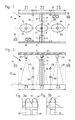
- Corridor 1 which is only shown schematically in FIGS. 1 and 2, is spatially limited by a floor 2, a ceiling 3 and two parallel side walls 4 and 5, the latter being able to be spaced apart by 2 m and more.
- two sliding doors 7 and 8 colliding in the vertical longitudinal center plane 6 are arranged, each of which can be pushed between two transverse walls 9 and 10 or 11 and 12 if the corridor 1 is to be cleared for passage.
- the two sliding doors 7 and 8 are driven electrically by means of a motor 32, which is shown schematically in FIG. 4.
- a scanning device 13 is arranged in the longitudinal center plane 6 in the form of a passive IR sensor 14 (in the following PIR sensor) which generates signals 15, 16, 17 that generate significant signals
- Touch area has the shape of an elliptical cone 18.
- transverse light barriers LS1 and LS2 are each double at a short distance Arranged one above the other, which define a central zone Z2, the entry of which leads to either a positive or a negative signal.
- light sensors LT1 and LT2 are arranged on the ceiling 3, each with likewise elliptical scanning cones, which are connected to the scanning device 13, i. H. with the PIR sensor 14 in a straight row running parallel to the two side walls 4 and 5, namely in the longitudinal center plane 6.
- the PIR sensor 14 is able to generate signals 15, 16 and 17 that are significant to people, i.e. different signals, as shown in FIGS 3a and 3b are shown. With the help of these person-significant signals, it is possible to recognize whether only one person or whether more people pass through the cone 18 of the feeler device 13 and to derive an error signal or a positive registration signal therefrom with the aid of differentiators.
- Such an error signal arises, for example, when, as shown in FIG two people pass the key cone 18 and the two person-significant signals 15 and 16 emerge at a short distance from one another, from which two square signals 25 and 26 which follow one another at short intervals are formed, which lead to an error signal. If, on the other hand, only one person properly passes the key cone 18, only one person-significant signal 17 is produced, from which a single square-wave signal 25 is derived, which is evaluated as a positive registration signal.
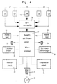
- the monitoring device also includes an electronic evaluation and control unit 27 in the form of a microprocessor, to which the signals from the light sensors LT1, LT2, the light barriers LS1, LS2 and the scanning device 13 are fed via a signal preprocessing unit 28.
- the two card readers 21 and 22 and the two red-green traffic lights 23 and 24 are also connected to the evaluation and control unit 27.
- a status indicator 29 and safety devices 30 can be connected to the evaluation and control unit 27, each of which signals the current status of the system.
- the drive motor 32 of the two sliding doors 7 and 8 is also controlled by the evaluation and control unit 27 via a motor control 31.
- a control unit 33 and a programming unit 34 are connected to the evaluation and control unit 27.
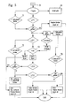
- the evaluation and control unit 27 is provided with three time control devices T1, T2, T3 (FIG. 5), not shown in the drawing, which monitor time periods within which the signals of the light sensors LT1, LT2, the light barriers LS1, LS2 and the key device 13 and the two ID card readers 21, 22 must be available during a passage in order to maintain the release or to prevent the corridor 1 from being blocked and the generation of an error message.
- T1, T2, T3 FIG. 5
- a first time control T1 is provided, which monitors the chronological sequence of the signals from the card reader 21, 22 used in each case and the light button LT1 or LT2 located on the same side of corridor 1.
- a second time control device monitors the temporal signal sequence of those determining the key zone Z2 Light barriers LS1 and LS2, while a third time control device T3 monitors the length of time of the entire passage, which is determined by the release signal of an identification reader 21 or 22 and the signal of the light button LT2 or LT1 located at the opposite end of the corridor.
- the time control devices are set to certain preselected time spans, which can be predetermined by appropriate programming and, if necessary, also changed.
- These time control devices T1, T2, and T3 are symbolically represented in the flow chart of the monitoring control device of a passage shown in FIG. 5 in FIG. 5.
- the monitoring control device is equipped with the additional light sensors LT1 and LT2.
- the operation of the monitoring device described above will now be explained in more detail using this flow chart.
- the functional description is limited to a passage in only one direction.
- the monitoring device is in the basic state, ie the doors 7 and 8 are closed, the traffic lights 23 and 24 show red and none of the three zones Z1, Z2 and Z3 is occupied.
- the card readers 21 and 22 and the monitoring sensors, LT1, LS1, LS2 and LT2, are activated with the exception of the PIR sensor 14.
- the release causes the traffic light 23 arranged on the same side to switch from red to green.
- the traffic light 24 on the exit side of the corridor 1 remains switched to red.
- a first time control is started, which monitors whether the granted release of corridor 1 is also used, i.e. whether corridor 1 is entered by a person or not.
- the person requesting passage must now enter the key cone 19 of the light sensor LT1 in order to maintain the release.
- the light sensor LT1 sends a signal to the evaluation and control unit, thus acknowledging the first control time.
- the release is confirmed and the doors 7 and 8 are opened to a passage width of about 60 cm.
- the signal from the light switch LT1 is absolutely necessary In order to maintain the release of corridor 1, the person who wants to pass through the corridor is also given the passageway which the person must take in order to trigger the positive signal of the light sensor LT1.
- the confirmation signal from the light button LT1 resets the first time control device without evaluation and starts a third control time with the activation of a third time control device T3.
- the first control time is deemed not to have been acknowledged. With the expiry of the first control time, the time control device T1 of the first time control sends a negative signal to the evaluation and control unit, so that the monitoring device resets itself to the basic state if none of the three zones Z1, Z2, Z3 is occupied. The traffic light 23 jumps back to red and the release is deleted. The start of the third inspection time is also canceled. After this first inspection time, the person can no longer pass through corridor 1, even if he has previously shown himself to be authorized at the card reader 21. In order to achieve a new release, the person must press the card reader again.
- zone Z1 has passed through the cone 19 of the light sensor LT1 correctly, the doors 7, 8 remain open and the person passes through the light barriers LS1 into the second zone Z2 of the corridor 1.
- the light barriers LS1 set a positive signal the evaluation and control unit, whereby a second time control device T2, which the second control time starts, is activated.
- Zone Z2 must be passed within this control time in order to maintain the release.
- the signal for acknowledging the second control time is emitted by the light barriers LS2 to the evaluation and control unit.
- the second control time expires without an acknowledgment from a signal from the light barriers LS2, i.e. without passing through, an error signal is sent from the time control device T2 to the evaluation and control unit.
- This signal causes the doors 7, 8 to close, the traffic light 24 to switch to red and the release to be canceled.
- the monitoring device is again in the basic state and can be reactivated.
- the sensor system checks whether the lock is passed in the correct direction and whether one or more people use the corridor.
- the evaluation and control unit By checking the correct signal sequence by the evaluation and control unit, it can be determined whether the person is actually moving in the correct direction through corridor 1.
- the signals that arrive at the evaluation and control device must arrive there in the following order: the release signal of the card reader 21, the confirmation signal of the light button LT1 and the signal from the light barrier LS1.
- FIGS. 3a and 3b show the signals of the PIR sensor 14, which are shown by way of example in FIGS. 3a and 3b.
- 3a shows the signal curve over time that results when two people pass through corridor 1 in close succession.
- Curve 15 is generated by the first person and curve 16 by the second person.
- the analog curve signals 15 and 16 are converted into digital signal pulses 25 and 26 by a downstream digitizing device. If such a double pulse 25, 26, as shown in FIG. 3a, reaches the PIR sensor to the evaluation and control unit, it is recognized as a negative signal and an alarm is triggered.
- doors 7, 8 are closed, the traffic light is switched to red and the release is deleted. After the unauthorized persons have left the corridor again, the monitoring device returns to its basic state.
- the evaluation and control unit receives only a pulse 25 from the PIR sensor, as can be seen from FIG. 3b, and then the signal the second light barrier LS2 within the second control time, the second control time is acknowledged and the second time control is deleted. At the same time, the doors 7, 8 are closed behind the person who has passed through.
- the person In order to generate a positive message of a completed passage, the person must pass through the sensor cone 20 of the second light switch LT2. This must be done within the third control period. If the signal of the light button LT2 is available in good time, the traffic light 24 is simultaneously switched back to red, the release and the third time control are deleted. As soon as all three zones of the monitoring device are unoccupied, i.e. If there are no more people in these zones, the monitoring device is again in the basic state and can be activated for a further passage.
- the advantage of the surveillance device according to the invention for a passenger corridor can be seen in the fact that an unnoticed passage through a corridor to be monitored is practically impossible.
- the corridor cannot be blocked if, for example, an authorized person uses a card reader to release the corridor, but this authorization is not used by the authorized person.
- the time control device sends an error signal to the evaluation and control unit, which leads to the release being canceled.
- the monitoring device It resets itself to the basic state after the first time control has expired. Without this first time control device, the monitoring device would not automatically reset itself to the basic state and the badge readers would not be usable for a new release, since the monitoring device waits for a signal from the sensors LT1 or LT2.
Priority Applications (1)
| Application Number | Priority Date | Filing Date | Title |
|---|---|---|---|
| AT9090124363T ATE105091T1 (de) | 1990-01-17 | 1990-12-17 | Ueberwachungsvorrichtung fuer einen personenkorridor. |
Applications Claiming Priority (2)
| Application Number | Priority Date | Filing Date | Title |
|---|---|---|---|
| DE4001219A DE4001219C1 (fr) | 1990-01-17 | 1990-01-17 | |
| DE4001219 | 1990-01-17 |
Publications (3)
| Publication Number | Publication Date |
|---|---|
| EP0437757A2 true EP0437757A2 (fr) | 1991-07-24 |
| EP0437757A3 EP0437757A3 (en) | 1991-12-18 |
| EP0437757B1 EP0437757B1 (fr) | 1994-04-27 |
Family
ID=6398248
Family Applications (1)
| Application Number | Title | Priority Date | Filing Date |
|---|---|---|---|
| EP90124363A Expired - Lifetime EP0437757B1 (fr) | 1990-01-17 | 1990-12-17 | Dispositif appliqué à la surveillance de passage de personnes dans un corridor |
Country Status (3)
| Country | Link |
|---|---|
| EP (1) | EP0437757B1 (fr) |
| AT (1) | ATE105091T1 (fr) |
| DE (1) | DE4001219C1 (fr) |
Cited By (8)
| Publication number | Priority date | Publication date | Assignee | Title |
|---|---|---|---|---|
| EP0622761A2 (fr) * | 1993-04-26 | 1994-11-02 | Autec Automations-Technik Beeler Werner | Procédé pour séparer des objets |
| FR2713805A1 (fr) * | 1993-12-15 | 1995-06-16 | Alkan Sa | Système antifraude à l'usage des transports publics. |
| EP0908854A2 (fr) * | 1997-10-13 | 1999-04-14 | Michel Gallet | Procédé et dispositif pour la détection de personnes et d'objets dans un espace donné |
| WO2001075809A2 (fr) * | 2000-04-01 | 2001-10-11 | Integrated Design Limited | Surveillance de l'entree par des passages |
| WO2003091955A1 (fr) * | 2002-04-24 | 2003-11-06 | Markus Oppenberger | Methode de comptage de personnes |
| FR2844901A1 (fr) * | 2002-09-20 | 2004-03-26 | Thales Sa | Procede et dispositif de controle d'acces. |
| WO2004059591A2 (fr) * | 2002-12-31 | 2004-07-15 | Automatic Systems | Porte automatisee et procede associe pour permettre ou interdire un acces |
| FR2919413A1 (fr) * | 2007-07-23 | 2009-01-30 | Gunnebo Electronic Security Sa | Procede de surveillance d'un espace accessible par une porte de controle et porte de controle. |
Families Citing this family (9)
| Publication number | Priority date | Publication date | Assignee | Title |
|---|---|---|---|---|
| DE4120816C2 (de) * | 1991-06-25 | 2001-11-08 | Rabotek Ind Comp Gmbh | Verfahren und Einrichtung zur Überwachung von Tunnelbauwerken |
| DE4220508C2 (de) * | 1992-06-22 | 1998-08-20 | Iris Gmbh Infrared & Intellige | Vorrichtung zur Erfassung von Personen |
| DE4312186C2 (de) * | 1993-04-14 | 1995-04-06 | Sick Optik Elektronik Erwin | Verfahren und Vorrichtungen zur Feststellung von in einem Überwachungsbereich vorhandenen Gegenständen und/oder zur Feststellung deren Position |
| GB2303170A (en) * | 1995-03-31 | 1997-02-12 | Ho Cheuk Fai | Improvements in or relating to security door locks |
| WO1996030876A1 (fr) * | 1995-03-31 | 1996-10-03 | Cheuk Fai Ho | Verrous de securite ameliores |
| DE19548778A1 (de) * | 1995-12-23 | 1996-08-14 | Jan Goernemann | Verfahren zur Fahrgastabfertigung ohne Zeitverlust mit gleichzeitiger Kontrolle der Gültigkeit und der Erfassung von Fahrgaststatistiken |
| WO2009086928A1 (fr) * | 2008-01-08 | 2009-07-16 | Automatic Systems | Procede, systeme et installation de detection pour garantir l'unicite de passage d'un objet |
| DE202014005940U1 (de) | 2014-07-23 | 2014-09-04 | Magnetic Autocontrol Gmbh | Vorrichtung zur Überwachung und Verfolgung von Personen und/oder Gegenständen an Personendurchgangssperren oder Vereinzelungsanlagen |
| DE102017106307A1 (de) | 2017-03-23 | 2018-09-27 | Eq-3 Holding Gmbh | Vorrichtung und Verfahren zur Richtungserkennung in Durchgängen |
Citations (5)
| Publication number | Priority date | Publication date | Assignee | Title |
|---|---|---|---|---|
| US4000400A (en) * | 1975-04-09 | 1976-12-28 | Elder Clarence L | Bidirectional monitoring and control system |
| US4528679A (en) * | 1983-03-14 | 1985-07-09 | General Signal Corporation | Automatic counting system for passages |
| DE3623792C1 (de) * | 1986-07-15 | 1987-12-10 | Messerschmitt Boelkow Blohm | Einrichtung zur Feststellung der Personenzahl und Richtung innerhalb eines zu ueberwachenden Raumes oder einer Durchgangsschleuse |
| FR2602894A1 (fr) * | 1986-07-29 | 1988-02-19 | Besancon Cie Transports | Systeme de comptage de mobiles traversant dans les deux sens une voie unique, a l'aide de cellules photoelectriques de detection directe |
| DE3832428A1 (de) * | 1987-09-26 | 1989-04-06 | Matsushita Electric Works Ltd | Personen-erfassungsvorrichtung |
Family Cites Families (1)
| Publication number | Priority date | Publication date | Assignee | Title |
|---|---|---|---|---|
| GB1263542A (en) * | 1968-06-14 | 1972-02-09 | Omron Tateisi Electronics Co | An automatic ticket gate |
-
1990
- 1990-01-17 DE DE4001219A patent/DE4001219C1/de not_active Expired - Fee Related
- 1990-12-17 EP EP90124363A patent/EP0437757B1/fr not_active Expired - Lifetime
- 1990-12-17 AT AT9090124363T patent/ATE105091T1/de not_active IP Right Cessation
Patent Citations (5)
| Publication number | Priority date | Publication date | Assignee | Title |
|---|---|---|---|---|
| US4000400A (en) * | 1975-04-09 | 1976-12-28 | Elder Clarence L | Bidirectional monitoring and control system |
| US4528679A (en) * | 1983-03-14 | 1985-07-09 | General Signal Corporation | Automatic counting system for passages |
| DE3623792C1 (de) * | 1986-07-15 | 1987-12-10 | Messerschmitt Boelkow Blohm | Einrichtung zur Feststellung der Personenzahl und Richtung innerhalb eines zu ueberwachenden Raumes oder einer Durchgangsschleuse |
| FR2602894A1 (fr) * | 1986-07-29 | 1988-02-19 | Besancon Cie Transports | Systeme de comptage de mobiles traversant dans les deux sens une voie unique, a l'aide de cellules photoelectriques de detection directe |
| DE3832428A1 (de) * | 1987-09-26 | 1989-04-06 | Matsushita Electric Works Ltd | Personen-erfassungsvorrichtung |
Cited By (15)
| Publication number | Priority date | Publication date | Assignee | Title |
|---|---|---|---|---|
| EP0622761A2 (fr) * | 1993-04-26 | 1994-11-02 | Autec Automations-Technik Beeler Werner | Procédé pour séparer des objets |
| EP0622761B1 (fr) * | 1993-04-26 | 1998-07-08 | Autec Automations-Technik Beeler Werner | Procédé pour séparer des objets |
| FR2713805A1 (fr) * | 1993-12-15 | 1995-06-16 | Alkan Sa | Système antifraude à l'usage des transports publics. |
| EP0908854A2 (fr) * | 1997-10-13 | 1999-04-14 | Michel Gallet | Procédé et dispositif pour la détection de personnes et d'objets dans un espace donné |
| EP0908854A3 (fr) * | 1997-10-13 | 1999-12-15 | Michel Gallet | Procédé et dispositif pour la détection de personnes et d'objets dans un espace donné |
| WO2001075809A3 (fr) * | 2000-04-01 | 2002-01-03 | Integrated Design Ltd | Surveillance de l'entree par des passages |
| WO2001075809A2 (fr) * | 2000-04-01 | 2001-10-11 | Integrated Design Limited | Surveillance de l'entree par des passages |
| WO2003091955A1 (fr) * | 2002-04-24 | 2003-11-06 | Markus Oppenberger | Methode de comptage de personnes |
| FR2844901A1 (fr) * | 2002-09-20 | 2004-03-26 | Thales Sa | Procede et dispositif de controle d'acces. |
| WO2004059591A2 (fr) * | 2002-12-31 | 2004-07-15 | Automatic Systems | Porte automatisee et procede associe pour permettre ou interdire un acces |
| WO2004059591A3 (fr) * | 2002-12-31 | 2004-08-26 | Automatic Systems | Porte automatisee et procede associe pour permettre ou interdire un acces |
| US7617974B2 (en) | 2002-12-31 | 2009-11-17 | Automatic Systems | Automatic gate and associated method for permitting or preventing access |
| FR2919413A1 (fr) * | 2007-07-23 | 2009-01-30 | Gunnebo Electronic Security Sa | Procede de surveillance d'un espace accessible par une porte de controle et porte de controle. |
| WO2009016311A3 (fr) * | 2007-07-23 | 2009-04-09 | Gunnebo Electronic Security So | Procede de surveillance d'un espace accessible par une porte de contrôle et porte de contrôle |
| EA016966B1 (ru) * | 2007-07-23 | 2012-08-30 | Ганнебо Электроник Секьюрити (Сосьете Пар Аксьон Симплифье) | Способ наблюдения за пространством, доступным через контрольную дверь, и контрольная дверь |
Also Published As
| Publication number | Publication date |
|---|---|
| EP0437757A3 (en) | 1991-12-18 |
| ATE105091T1 (de) | 1994-05-15 |
| EP0437757B1 (fr) | 1994-04-27 |
| DE4001219C1 (fr) | 1991-04-25 |
Similar Documents
| Publication | Publication Date | Title |
|---|---|---|
| EP0437757B1 (fr) | Dispositif appliqué à la surveillance de passage de personnes dans un corridor | |
| EP0273965B1 (fr) | Installation pour determiner le nombre de personnes et leur direction de deplacement dans un local surveille ou un sas | |
| EP0215291B1 (fr) | Dispositif de serrage pour véhicules automobiles | |
| EP1750231B1 (fr) | Procédé pour établir automatiquement le nombre des personnes et/ou d'objets demeurant dans un sas | |
| DE60006411T2 (de) | Zählvorrichtung | |
| DE10146459B4 (de) | Verfahren zur Zutrittssicherung, Vorrichtung zur Zutrittskontrolle und Aufzugskabine | |
| EP2286393B1 (fr) | Dispositif de sécurité et procédé pour la surveillance d'une zone surveillée | |
| DE3532156C2 (fr) | ||
| DE1929922A1 (de) | Selbsttaetige Passierscheinkontrollsperre | |
| DE3420223A1 (de) | Optische tuersicherung | |
| DE19531323A1 (de) | Ein Diagnose- und/oder Überwachungsverfahren und eine Sicherheitseinrichtung zur Durchführung des Verfahrens für mindestens eine Tür, vorzugsweise in Flucht- und Rettungswegen | |
| DE2216400C2 (de) | Zugangskontrollvorrichtung | |
| EP1103037B1 (fr) | Procede et dispositif pour controler si des personnes ou des objets mobiles penetrent dans une zone ou quittent cette derniere | |
| DE19809235C2 (de) | Durchgangsschleuse und Verfahren zum Betrieb einer solchen Durchgangsschleuse | |
| DE2747388A1 (de) | Elektronisches kontrollsystem | |
| EP0747865A2 (fr) | Dispositif de détermination du sens de déplacement d'une personne | |
| DE102021115356A1 (de) | Durchgangskontrollvorrichtung | |
| EP0474975A1 (fr) | Dispositif de contrôle d'accès | |
| DE2840716A1 (de) | Einrichtung und verfahren zur automatischen durchgangskontrolle | |
| DE19901487A1 (de) | Automatischer Türantrieb bzw. zugehörige Steuerungseinrichtung | |
| DE3503933C2 (fr) | ||
| EP3575666A1 (fr) | Dispositif de sécurisation d'une zone à risque d'une installation | |
| DE10237500B4 (de) | Überwachungssystem | |
| DE19925523C2 (de) | Verfahren und Vorrichtung zum Kontrollieren des Betretens oder Verlassens eines Bereichs durch Personen oder bewegliche Sachen | |
| DE102004048022B4 (de) | Vorrichtung zur Scharfschaltung und Unscharfschaltung einer Alarmanlage |
Legal Events
| Date | Code | Title | Description |
|---|---|---|---|
| PUAI | Public reference made under article 153(3) epc to a published international application that has entered the european phase |
Free format text: ORIGINAL CODE: 0009012 |
|
| AK | Designated contracting states |
Kind code of ref document: A2 Designated state(s): AT CH FR GB LI NL |
|
| PUAL | Search report despatched |
Free format text: ORIGINAL CODE: 0009013 |
|
| AK | Designated contracting states |
Kind code of ref document: A3 Designated state(s): AT CH FR GB LI NL |
|
| 17P | Request for examination filed |
Effective date: 19920127 |
|
| 17Q | First examination report despatched |
Effective date: 19930716 |
|
| GRAA | (expected) grant |
Free format text: ORIGINAL CODE: 0009210 |
|
| AK | Designated contracting states |
Kind code of ref document: B1 Designated state(s): AT CH FR GB LI NL |
|
| REF | Corresponds to: |
Ref document number: 105091 Country of ref document: AT Date of ref document: 19940515 Kind code of ref document: T |
|
| ET | Fr: translation filed | ||
| GBT | Gb: translation of ep patent filed (gb section 77(6)(a)/1977) |
Effective date: 19940505 |
|
| PLBE | No opposition filed within time limit |
Free format text: ORIGINAL CODE: 0009261 |
|
| STAA | Information on the status of an ep patent application or granted ep patent |
Free format text: STATUS: NO OPPOSITION FILED WITHIN TIME LIMIT |
|
| 26N | No opposition filed | ||
| REG | Reference to a national code |
Ref country code: GB Ref legal event code: IF02 |
|
| PGFP | Annual fee paid to national office [announced via postgrant information from national office to epo] |
Ref country code: GB Payment date: 20031210 Year of fee payment: 14 |
|
| PGFP | Annual fee paid to national office [announced via postgrant information from national office to epo] |
Ref country code: AT Payment date: 20031211 Year of fee payment: 14 |
|
| PGFP | Annual fee paid to national office [announced via postgrant information from national office to epo] |
Ref country code: FR Payment date: 20031216 Year of fee payment: 14 |
|
| PGFP | Annual fee paid to national office [announced via postgrant information from national office to epo] |
Ref country code: CH Payment date: 20031219 Year of fee payment: 14 |
|
| PGFP | Annual fee paid to national office [announced via postgrant information from national office to epo] |
Ref country code: NL Payment date: 20031224 Year of fee payment: 14 |
|
| PG25 | Lapsed in a contracting state [announced via postgrant information from national office to epo] |
Ref country code: GB Free format text: LAPSE BECAUSE OF NON-PAYMENT OF DUE FEES Effective date: 20041217 Ref country code: AT Free format text: LAPSE BECAUSE OF NON-PAYMENT OF DUE FEES Effective date: 20041217 |
|
| PG25 | Lapsed in a contracting state [announced via postgrant information from national office to epo] |
Ref country code: LI Free format text: LAPSE BECAUSE OF NON-PAYMENT OF DUE FEES Effective date: 20041231 Ref country code: CH Free format text: LAPSE BECAUSE OF NON-PAYMENT OF DUE FEES Effective date: 20041231 |
|
| PG25 | Lapsed in a contracting state [announced via postgrant information from national office to epo] |
Ref country code: NL Free format text: LAPSE BECAUSE OF NON-PAYMENT OF DUE FEES Effective date: 20050701 |
|
| GBPC | Gb: european patent ceased through non-payment of renewal fee |
Effective date: 20041217 |
|
| REG | Reference to a national code |
Ref country code: CH Ref legal event code: PL |
|
| PG25 | Lapsed in a contracting state [announced via postgrant information from national office to epo] |
Ref country code: FR Free format text: LAPSE BECAUSE OF NON-PAYMENT OF DUE FEES Effective date: 20050831 |
|
| NLV4 | Nl: lapsed or anulled due to non-payment of the annual fee |
Effective date: 20050701 |
|
| REG | Reference to a national code |
Ref country code: FR Ref legal event code: ST |