EP0430890B1 - Elément de paroi pour la construction à sec de murs, système constructif pour la fixation de pentes et paroi de soutènement obtenue par le système - Google Patents
Elément de paroi pour la construction à sec de murs, système constructif pour la fixation de pentes et paroi de soutènement obtenue par le système Download PDFInfo
- Publication number
- EP0430890B1 EP0430890B1 EP90810915A EP90810915A EP0430890B1 EP 0430890 B1 EP0430890 B1 EP 0430890B1 EP 90810915 A EP90810915 A EP 90810915A EP 90810915 A EP90810915 A EP 90810915A EP 0430890 B1 EP0430890 B1 EP 0430890B1
- Authority
- EP
- European Patent Office
- Prior art keywords
- wall
- side walls
- shield
- walls
- trough
- Prior art date
- Legal status (The legal status is an assumption and is not a legal conclusion. Google has not performed a legal analysis and makes no representation as to the accuracy of the status listed.)
- Expired - Lifetime
Links
Images


Classifications
-
- E—FIXED CONSTRUCTIONS
- E02—HYDRAULIC ENGINEERING; FOUNDATIONS; SOIL SHIFTING
- E02D—FOUNDATIONS; EXCAVATIONS; EMBANKMENTS; UNDERGROUND OR UNDERWATER STRUCTURES
- E02D29/00—Independent underground or underwater structures; Retaining walls
- E02D29/02—Retaining or protecting walls
- E02D29/025—Retaining or protecting walls made up of similar modular elements stacked without mortar
Definitions
- the present invention relates to a wall element for the dry construction of walls according to the preamble of claim 1, a kit for fastening embankments according to claim 12 and an embankment wall according to claim 14.
- a similar element is described in CH-A-587 390, but which is intended for layering and for this purpose has two groove-like depressions arranged on the bottom underside which are perpendicular to the shield and which, in the case of staggered layered elements, over the side walls of the elements below come to rest.
- This provides such a retaining wall with extremely high stability because the elements cannot move laterally.
- the shield is formed higher than the side walls, so that upper elements arranged on a gap lie behind the shields of the two elements located below, and are thus pressed downward by the weight.
- the troughs are filled with soil or humus and can be planted. This means that the concrete wall can be greened on the one hand and on the other hand the roots of the plants create a connection backwards to the grown soil.
- both the shield and wing extend beyond the side walls on both sides.
- a transverse wall in the trough divides it into a front closed bowl and a rear trough that is open to the rear.
- the widened shields and the protruding wings give further chambers, which together with the bowls in front form calming basins near water courses or lakes in the area of the water level.
- a planting of the rear troughs is possible in that the bowls at least make it difficult to wash the soil out of the troughs.
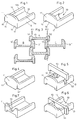
- bottom wall 10 shows the fundamentally known shape with bottom wall 10, a shield 11 standing vertically thereon and side walls 12, 13 arranged on both sides of bottom wall 10.
- bottom wall 10 has two parallel sides on its underside trough-shaped depressions 14, 15.
- the shield is rounded on the top and side and all end faces can also be rounded to create a natural stone same.
- the shield 11 can either align laterally with the side walls according to CH-A-587 390 or project beyond the side walls according to EP-A-0 047 718.
- the side walls 12 ', 13' and 12 '', 13 '' are dimensioned thicker than in the known embankment stone according to CH-A- 587 390, namely the upper end face 12a, 13a (Fig. 1) flattened and is located vertically above the trough-shaped recess 14, 15, such that in the case of elements layered in the composite, the bottom wall 10 of an element A below its side walls 12, 13 with side walls 13 'or 12' 'of elements B or . C is supported.
- the two vertical dash-dotted lines S1, S2 clearly show, the forces according to the arrows P1, P2 always press on side walls 13 ', 12 ⁇ , so that no moments can act on the support points that could destroy the element.
- the bottom underside could be formed with two lateral holding strips 16, 17 which protrude into the shield 11.
- the shield 11 in turn could also be extended downwards, so that the wide recess 18 between the holding strips 16, 17 remains invisible from the front.
- the plate 11 protruding laterally, at least at the top, permits the elements which are layered in the composite Fig. 1 or 2 with lots in front of the side walls 12, 13 queue at the rear of the shields 11 and thus get a stop against sliding forward.
- the layered wall experiences an angle of inclination, which is determined by the thickness of the shield 11.
- the elements can thus be layered vertically next to and on top of one another in such a way that the elements with their adjacent shields engage in these recesses 41, 42, so that no displacement by the thickness of the shields is necessary and the wall can be built up vertically. This means that there is no security with the hold behind the shields and the stones only hold due to the friction, which is sufficient in many cases.
- a slot-like recess 51, 52 in each of the two side walls 12, 13 be arranged at the same distance behind the shield 11.
- a plate for partitioning bank areas can also be provided with a plate-shaped partition 53 be created, which is provided with a front calming chamber 54 and a trough 55 open to the rear.
- the elements for all applications can be provided with such slot-like recesses 51, 52, because the particularly favorable arrangement of the supports, as shown in FIG possible destructive force, as was possible with previous forms of training.
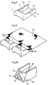
- the upper end faces 12a, 13a of the side walls 12, 13 could be provided with notches 71, 72 at the same distance behind the shield 11 (FIG. 8).
- a concrete iron 81 or the like could be inserted into these notches, around which a geotextile fabric 82 is folded and which can be inserted with its free end into the soil lying far to the rear in order to give the wall great stability .
- This shield 91 consists of three triangular surfaces 92, 93, 94, of which the front surface 92 is arranged perpendicular to the bottom wall 95 and an isosceles or represents equilateral triangle.
- the two further triangular surfaces 93, 94 are likewise isosceles or equilateral triangles, the base lines of which, in contrast to the first-mentioned triangle 92, now lie at the top and form the upper boundary.
- the bottom wall 10 can have a recess 20 at the rear. However, this could also be arranged in the center, so that the rear edge appears closed with a crossbar. With such a recess, the greater weight of the elements can be reduced due to the thicker side walls.
- the side walls 101, 102 in FIG. 11 have a greater distance at the shield-side end than at the free end, and the side walls 121, 122 in FIG. 12, on the other hand, have a smaller distance at the shield-side end than at the free end.
- the two embankment stones according to FIGS. 11 and 12 differ only in that, in the case of troughs 104, 124 of the same construction, with a wedge-shaped widening distance between the side walls 101, 102 and 121, 122, only the shield 103, 123 in each case at one of the two ends could be arranged.
- the shields 103, 123 are convexly curved upwards and the front edges can be rounded.
- a trough open at the top and rear is formed.
- the shield 103, 123 protrudes the respective side walls 101, 102 and 121, 122 at least upwards, but they could also protrude laterally. This creates a hold for the upper stone when building a wall and this cannot slide forward.
- An upwardly projecting transverse rib can be provided in the rear region of the bottom wall 104, 124 in order to form a bowl-shaped depression above the bottom wall. Such transverse ribs are not shown in FIGS. 11 and 12, since anyone can imagine such an increase.
- the purpose of the deepening thus formed is that water can be stored so that the soil does not dry out, even if the shield is exposed to strong sunshine. This means that the plants have moisture for the greening of the wall until their roots can grow into the soil behind the wall.
- the mentioned rib can serve a similar purpose in the stone according to FIG. 12, in that a constriction is also formed on the rear part of the stone in the bond of a wall.
- Recesses 107, 108, 127, 128 are arranged on the upper end faces 105, 106, 125, 126 of the side walls 101, 102, 121, 122.
- the shield 103 can also, if it has a tab 109 projecting below the floor 104 has to engage in these recesses and thus form a toothing.
- the bottom wall 104 can have two depressions 130, 131 in its lower surface. These depressions 130, 131 can be parallel to the side walls 101, 102 may be arranged, but they can also form a different angle to the front face of the shield, namely in such a way that when stones are layered, the side walls 101, 102 engage in the depressions 130, 131 and thus form a side toothing.
- the grooves can also be crossed or arranged in pairs in a V-shape, in order to enable intervention when using the same stones in the arrangement according to FIG. 15 or different stones in the arrangement according to FIG. 16.
- FIGS. 13 and 14 each show a wall, built with embankment stones according to FIG. 12. With such stones, both straight walls and concavely curved walls can be formed.
- FIG. 16 now shows a wall as it can advantageously be built using both types of embankment stones according to FIGS. 11 and 12. Although the horizontal lines are still emphasized here, at least the regularity in vertical terms is no longer given. This gives the wall a visible surface that is more pronounced of a natural stone wall than, for example, walls according to FIGS. 13-15.
- shields 103, 123 are shown with flat front walls, they can of course also be curved, as shown in FIGS. 13 to 16, where the shields are shown curved and pass smoothly into the side walls.
Claims (14)
- Elément de maçonnerie en béton pour la construction de murs de pierres sèches, avec un bouclier avant (11,91), deux parois latérales (12,13) s'étendant vers l'arrière et une paroi de fond (10,95) de sorte que l'élément de maçonnerie est constitué en forme d'auge, et dans lequel la paroi de fond (10,95) comporte sur sa face inférieure au moins une partie évidée (14,15,18) disposée parallèlement aux parois latérales (12,13,11,91), les parois latérales (12,13) sont plus étroites dans leur surfaces frontales (12a,13a) supérieures libres que dans leur base, au moins une partie marginale de la face inférieure de la paroi de fond comporte une partie évidée (14,15,18) disposée dans une région au-dessous d'une des parois latérales (12,13), et dans lequel chacune des parois latérales forme dans la région de la surface du fond, une bordure (16,17) extérieure en forme de nervure, s'étendant sur au moins une partie de la longueur de l'auge, caractérisé en ce que l'épaisseur des parois latérales (12,13) dans la région de leur base est plus grande que la largeur de ces bordures (16,17) en forme de nervure, ayant pour effet que pour des éléments de maçonnerie à joints réglés, la paroi de fond (10) d'un premier élément (A) soit supportée en dessous de ses parois latérales (12,13) par des parois latérales (13′ ou 12˝) d'éléments de maçonnerie (B ou C) se trouvant en dessous, de façon que des forces qui agissent à travers les parois latérales (12,13) du premier élément de maçonnerie (A) s'appliquent sur ces autres parois latérales (13′ ou 12˝) de sorte qu'aucun couple de forces ne peut agir sur les points d'appui entre les éléments de maçonnerie empilés, qui pourrait les détruire, et que le bouclier (11) et/ou la paroi de fond (10) et/ou les parois latérales (12,13) comporte au moins un évidement, ou que le bouclier (91) présente, sur sa paroi avant, plusieurs surfaces polygonales adjacentes (92,93,94) qui font des angles obtus les unes avec les autres.
- Elément suivant la revendication 1, caractérisé en ce que la partie évidée (18) est constituée de manière continue entre les bordures (16,17).
- Elément suivant la revendication 1 ou 2, caractérisé en ce que la paroi de fond (10) comporte un trou (20) qui n'est pas délimité vers l'arrière.
- Elément suivant l'une des revendications 1 à 3, caractérisé en ce que le bouclier (11) a, devant chacune des deux bordures (16,17) et dans le région du fond, un creux (41,42), dont la largeur est égale ou plus grande que la largeur des surfaces frontales (12a,13a) des parois latérales (12,13).
- Elément suivant la revendication 4 ou 5, caractérisé en ce que le bouclier (11) comporte à peu près au milieu une échancrure (73) en forme de selle.
- Elément suivant l'une des revendications 1 à 5, caractérisé en ce que chaque paroi latérale (12,13) comporte, dans sa surface frontale (12a,13a), une encoche (71,72) en forme de selle à même distance derrière le bouclier (11).
- Elément suivant l'une des revendications 1 à 5, caractérisé en ce que, dans chaque paroi latérale, est ménagée une fente (51,52) à parois latérales qui coupe toute la hauteur des parois parallèles, et en ce qu'il est prévu des panneaux d'insertion (53) pour subdiviser l'élément en forme d'auge en une cuve (54) avant et en une auge (55) arrière.
- Elément suivant l'une des revendications 1 à 7, caractérisé en ce que le bouclier (11) dépasse les parois latérales (12,13), tant latéralement qu'en hauteur.
- Elément suivant la revendication 1, caractérisé en ce que les polygones sont des triangles, que la hauteur d'un (92) de ces triangles se trouve dans le plan vertical médian de l'auge, que la base de ce triangle (92) forme le bord avant de la surface de fond, que deux autres triangles (93,94) se raccordent de part et d'autre de ce triangle (92) et constituent, par leurs bases, les bords avant supérieurs du bouclier (91), et que les autres surfaces triangulaires (93,94) font un angle obtus avec la surface (92) mentionnée en premier.
- Elément suivant la revendication 9, caractérisé en ce que les deux autres surfaces triangulaires (93,94) font le même angle obtus avec la surface (92) mentionnée en premier.
- Elément suivant la revendication 9 ou 10, caractérisé en ce que la surface (92) mentionnée en premier est constituée en parpaing concassé.
- Jeu d'éléments de construction pour la fixation de talus et pour le gazonnage du talus ayant des éléments de maçonnerie suivant l'une des revendications 1 à 11, caractérisé en ce que des parois latérales (101,102;121,122) et une paroi de fond (104,124) servant d'auge (100,120) sont disposées à une distance se rétrécissant de manière cunéiforme entre les parois latérales (101,102;121,122), et en ce que le bouclier (103,123) est disposé sur le côté le plus large de l'auge ou sur le côté le plus étroit de l'auge.
- Jeu d'éléments de construction suivant la revendication 12, caractérisé en ce que le bouclier (103,123) dépasse au moins en hauteur les parois latérales (101,102;121,122), est incurvé vers le haut, de manière convexe, et s'adapte aux parois latérales (101,102;121,122) par une courbure latérale.
- Mur de talus formé à l'aide du jeu d'éléments de construction suivant la revendication 12, caractérisé en ce que, pour des parties concaves du mur, il est prévu de préférence des éléments ayant le bouclier à l'extrémité étroite de l'auge, pour des parties convexes du mur de préférence des éléments ayant le bouclier à l'extrémité large de l'auge, et pour des murs droits, il est prévu, d'utiliser à la fois des éléments d'un type et de l'autre, mélangés entre eux.
Applications Claiming Priority (2)
| Application Number | Priority Date | Filing Date | Title |
|---|---|---|---|
| CH4282/89 | 1989-11-30 | ||
| CH428289 | 1989-11-30 |
Publications (2)
| Publication Number | Publication Date |
|---|---|
| EP0430890A1 EP0430890A1 (fr) | 1991-06-05 |
| EP0430890B1 true EP0430890B1 (fr) | 1994-06-01 |
Family
ID=4273205
Family Applications (1)
| Application Number | Title | Priority Date | Filing Date |
|---|---|---|---|
| EP90810915A Expired - Lifetime EP0430890B1 (fr) | 1989-11-30 | 1990-11-26 | Elément de paroi pour la construction à sec de murs, système constructif pour la fixation de pentes et paroi de soutènement obtenue par le système |
Country Status (12)
| Country | Link |
|---|---|
| US (1) | US5177925A (fr) |
| EP (1) | EP0430890B1 (fr) |
| JP (1) | JPH0473328A (fr) |
| CN (1) | CN1052161A (fr) |
| AT (1) | ATE106482T1 (fr) |
| BR (1) | BR9006058A (fr) |
| CA (1) | CA2031077A1 (fr) |
| DE (1) | DE59005929D1 (fr) |
| ES (1) | ES2057511T3 (fr) |
| NO (1) | NO905152L (fr) |
| PT (1) | PT96057A (fr) |
| ZA (1) | ZA909485B (fr) |
Cited By (1)
| Publication number | Priority date | Publication date | Assignee | Title |
|---|---|---|---|---|
| US5797706A (en) | 1993-06-24 | 1998-08-25 | Societe Civile Des Brevets Henri Vidal | Earth structures |
Families Citing this family (25)
| Publication number | Priority date | Publication date | Assignee | Title |
|---|---|---|---|---|
| GB9123556D0 (en) * | 1991-11-06 | 1992-01-02 | Vidal Henri Brevets | Facing element and facing system |
| FR2692610B1 (fr) * | 1992-06-18 | 1995-01-13 | Andre Pieyre | Elément de soutènement. |
| US5624211A (en) * | 1993-03-31 | 1997-04-29 | Societe Civile Des Brevets Henri C. Vidal | Modular block retaining wall construction and components |
| US5474405A (en) * | 1993-03-31 | 1995-12-12 | Societe Civile Des Brevets Henri C. Vidal | Low elevation wall construction |
| US5507599A (en) * | 1993-03-31 | 1996-04-16 | Societe Civile Des Brevets Henri C. Vidal | Modular block retaining wall construction and components |
| DE4333942A1 (de) * | 1993-10-06 | 1995-04-13 | Sf Koop Gmbh Beton Konzepte | Bausatz aus Beton-Formsteinen sowie eine Vorrichtung zur Herstellung derselben |
| US5564865A (en) * | 1993-12-17 | 1996-10-15 | Jansson; Jan E. | Concrete module for retaining wall and improved retaining wall |
| US5499477A (en) * | 1993-12-30 | 1996-03-19 | Cancarb Limited | Carbon black refractory system |
| US5568999A (en) * | 1995-04-03 | 1996-10-29 | The Tensar Corporation | Retaining wall block system |
| US5601384A (en) * | 1995-06-07 | 1997-02-11 | Keystone Retaining Wall Systems, Inc. | Plantable retaining wall |
| US5913790A (en) * | 1995-06-07 | 1999-06-22 | Keystone Retaining Wall Systems, Inc. | Plantable retaining wall block |
| US5658098A (en) * | 1995-07-26 | 1997-08-19 | Hercules Manufacturing, Inc. | Polymeric retaining wall building block |
| JPH09165762A (ja) * | 1995-08-18 | 1997-06-24 | Soc Civile Des Brevets De Henri Vidal | 安定化された盛土構造体の表面被覆要素 |
| USD387434S (en) * | 1996-01-03 | 1997-12-09 | Keystone Retaining Wall Systems, Inc. | Front face of a plantable retaining wall block |
| JPH09256375A (ja) * | 1996-03-18 | 1997-09-30 | Taiyo Cement Kogyo Kk | 土留めブロック |
| US5851088A (en) * | 1997-08-04 | 1998-12-22 | The Tensar Corporation | Modular retaining wall block system including wall blocks having replaceable dual purpose facing panels and removable spacing tabs |
| US5987846A (en) * | 1998-01-16 | 1999-11-23 | Nahas; Michael | Wallboard fastening member and methods of using the same |
| CH693645A5 (de) * | 1999-04-29 | 2003-11-28 | Tschuemperlin Ag A | Trockenmauerelement. |
| US6505999B1 (en) * | 2001-05-24 | 2003-01-14 | Huesker, Inc. | Retaining wall structure for soil stabilization including double layer of geogrid web material to provide high strength connection with backfill material |
| US8707642B2 (en) | 2002-07-11 | 2014-04-29 | Michael G. Nahas | Sheet material hanging methods and hanging members therefore |
| US6761509B2 (en) * | 2002-07-26 | 2004-07-13 | Jan Erik Jansson | Concrete module for retaining wall and improved retaining wall |
| US7524144B2 (en) * | 2004-06-22 | 2009-04-28 | Allan Block Corporation | Retaining wall |
| NZ591508A (en) * | 2008-08-15 | 2013-03-28 | Smart Slope Llc | Retaining wall building block with cavity defined by bottom, front and side walls |
| DE102010036185A1 (de) * | 2010-09-02 | 2012-03-08 | Christian Gartner | Trockenmauerelement für Schallschutzwände oder Hangabsicherungen |
| US9428878B2 (en) * | 2012-05-22 | 2016-08-30 | Westblock Systems, Inc. | Retaining wall system |
Family Cites Families (12)
| Publication number | Priority date | Publication date | Assignee | Title |
|---|---|---|---|---|
| US3418774A (en) * | 1967-01-06 | 1968-12-31 | Kocher Alfred Lawrence | Building block and wall made therefrom |
| CH587390A5 (fr) * | 1974-09-19 | 1977-04-29 | Winkler Bernhard | |
| US4016693A (en) * | 1975-08-22 | 1977-04-12 | Warren Insulated Bloc, Inc. | Insulated masonry block |
| HU182851B (en) * | 1978-06-16 | 1984-03-28 | Betonutepitoe Vallalat | Prop member for sustaining walls of reinforced soil type closing built earthworks |
| CH636922A5 (de) * | 1979-01-04 | 1983-06-30 | Rolf Scheiwiller | Satz von stuetzmauer-elementen und dessen verwendung. |
| EP0047718B1 (fr) * | 1980-09-05 | 1984-05-30 | Steiner Silidur AG | Bloc creux pour la construction de berges en pente |
| US4379659A (en) * | 1980-09-05 | 1983-04-12 | Steiner Silidur A.G. | Building blocks |
| US4380887A (en) * | 1980-10-06 | 1983-04-26 | Lee Kenneth S | Insulated structural block |
| US4532748A (en) * | 1982-01-06 | 1985-08-06 | Rotherham William D B | Building block |
| US4802320A (en) * | 1986-09-15 | 1989-02-07 | Keystone Retaining Wall Systems, Inc. | Retaining wall block |
| DE3722412A1 (de) * | 1987-07-07 | 1989-03-09 | Herbert Dipl Ing Kwiatkowski | Offene rasterstuetzmauer aus betonsteinen |
| US5072566A (en) * | 1990-09-24 | 1991-12-17 | Zeidman Philip A | Landscaping block |
-
1990
- 1990-11-09 BR BR909006058A patent/BR9006058A/pt not_active Application Discontinuation
- 1990-11-26 AT AT90810915T patent/ATE106482T1/de active
- 1990-11-26 ZA ZA909485A patent/ZA909485B/xx unknown
- 1990-11-26 EP EP90810915A patent/EP0430890B1/fr not_active Expired - Lifetime
- 1990-11-26 DE DE59005929T patent/DE59005929D1/de not_active Expired - Fee Related
- 1990-11-26 ES ES90810915T patent/ES2057511T3/es not_active Expired - Lifetime
- 1990-11-28 NO NO90905152A patent/NO905152L/no unknown
- 1990-11-29 CN CN90109473A patent/CN1052161A/zh active Pending
- 1990-11-29 CA CA002031077A patent/CA2031077A1/fr not_active Abandoned
- 1990-11-29 US US07/619,725 patent/US5177925A/en not_active Expired - Fee Related
- 1990-11-30 PT PT96057A patent/PT96057A/pt not_active Application Discontinuation
- 1990-11-30 JP JP2330859A patent/JPH0473328A/ja active Pending
Cited By (1)
| Publication number | Priority date | Publication date | Assignee | Title |
|---|---|---|---|---|
| US5797706A (en) | 1993-06-24 | 1998-08-25 | Societe Civile Des Brevets Henri Vidal | Earth structures |
Also Published As
| Publication number | Publication date |
|---|---|
| ZA909485B (en) | 1991-11-27 |
| PT96057A (pt) | 1992-08-31 |
| CA2031077A1 (fr) | 1991-05-31 |
| ES2057511T3 (es) | 1994-10-16 |
| CN1052161A (zh) | 1991-06-12 |
| NO905152L (no) | 1991-05-31 |
| US5177925A (en) | 1993-01-12 |
| BR9006058A (pt) | 1991-09-24 |
| DE59005929D1 (de) | 1994-07-07 |
| EP0430890A1 (fr) | 1991-06-05 |
| ATE106482T1 (de) | 1994-06-15 |
| JPH0473328A (ja) | 1992-03-09 |
| NO905152D0 (no) | 1990-11-28 |
Similar Documents
| Publication | Publication Date | Title |
|---|---|---|
| EP0430890B1 (fr) | Elément de paroi pour la construction à sec de murs, système constructif pour la fixation de pentes et paroi de soutènement obtenue par le système | |
| EP0516957B2 (fr) | Panneau de treillis | |
| DE7824776U1 (de) | Element fuer hangsicherung | |
| DE2537408B2 (de) | Baustein zur Herstellung einer bepflanzbaren Stützmauer | |
| EP0322668A1 (fr) | Elément de construction pour l'érection d'un mur et mur érigé à l'aide de ces éléments | |
| DE3530049A1 (de) | Vorgefertigter hangstein aus beton | |
| DE1811932A1 (de) | Betonbalken,insbesondere fuer Raumgitter und Stuetzmauern | |
| EP0187615A1 (fr) | Jeu d'éléments pour constructions composites | |
| DE2809892A1 (de) | Elementbaustein | |
| DE7830516U1 (de) | Vorgefertigtes bauelement fuer mauern | |
| EP0024500B1 (fr) | Elément de construction en béton | |
| DE8213804U1 (de) | Bauelement | |
| EP0286957B1 (fr) | Mur anti-bruit support de végétation | |
| EP0034736B1 (fr) | Construction de recouvrement | |
| EP0343112A1 (fr) | Brique | |
| EP0986675B1 (fr) | Procede et dispositif pour lutter contre la formation d'avalanches, coulees de neige et analogues | |
| DE19707355C2 (de) | Fertigteilsatz zur Erstellung von Fundamenten für Baumroste | |
| DE3607630A1 (de) | Bodenbefestigung | |
| DE2819894C3 (de) | Aus Betonfertigteilen zusammengesetzte Wand | |
| AT401535B (de) | Durchwachsbare mauer | |
| DE3406663A1 (de) | Laermschutzwand | |
| DE8305162U1 (de) | Beton-pflanzstein | |
| EP0802283A2 (fr) | Panneau de treillis | |
| DE19613633A1 (de) | Selbsttragende Schutzwand | |
| DE7520030U (de) | Bauelementensatz zur erstellung von stuetzwaenden |
Legal Events
| Date | Code | Title | Description |
|---|---|---|---|
| PUAI | Public reference made under article 153(3) epc to a published international application that has entered the european phase |
Free format text: ORIGINAL CODE: 0009012 |
|
| AK | Designated contracting states |
Kind code of ref document: A1 Designated state(s): AT BE CH DE DK ES FR GB GR IT LI LU NL SE |
|
| 17P | Request for examination filed |
Effective date: 19910516 |
|
| 17Q | First examination report despatched |
Effective date: 19921013 |
|
| GRAA | (expected) grant |
Free format text: ORIGINAL CODE: 0009210 |
|
| AK | Designated contracting states |
Kind code of ref document: B1 Designated state(s): AT BE CH DE DK ES FR GB GR IT LI LU NL SE |
|
| PG25 | Lapsed in a contracting state [announced via postgrant information from national office to epo] |
Ref country code: NL Effective date: 19940601 Ref country code: GR Free format text: LAPSE BECAUSE OF FAILURE TO SUBMIT A TRANSLATION OF THE DESCRIPTION OR TO PAY THE FEE WITHIN THE PRESCRIBED TIME-LIMIT Effective date: 19940601 Ref country code: GB Effective date: 19940601 Ref country code: DK Effective date: 19940601 |
|
| REF | Corresponds to: |
Ref document number: 106482 Country of ref document: AT Date of ref document: 19940615 Kind code of ref document: T |
|
| REF | Corresponds to: |
Ref document number: 59005929 Country of ref document: DE Date of ref document: 19940707 |
|
| ITF | It: translation for a ep patent filed |
Owner name: BUGNION S.P.A. |
|
| PG25 | Lapsed in a contracting state [announced via postgrant information from national office to epo] |
Ref country code: SE Effective date: 19940901 |
|
| PGFP | Annual fee paid to national office [announced via postgrant information from national office to epo] |
Ref country code: FR Payment date: 19941007 Year of fee payment: 5 |
|
| PGFP | Annual fee paid to national office [announced via postgrant information from national office to epo] |
Ref country code: CH Payment date: 19941010 Year of fee payment: 5 |
|
| PGFP | Annual fee paid to national office [announced via postgrant information from national office to epo] |
Ref country code: AT Payment date: 19941013 Year of fee payment: 5 |
|
| REG | Reference to a national code |
Ref country code: ES Ref legal event code: FG2A Ref document number: 2057511 Country of ref document: ES Kind code of ref document: T3 |
|
| PGFP | Annual fee paid to national office [announced via postgrant information from national office to epo] |
Ref country code: BE Payment date: 19941020 Year of fee payment: 5 |
|
| ET | Fr: translation filed | ||
| PGFP | Annual fee paid to national office [announced via postgrant information from national office to epo] |
Ref country code: DE Payment date: 19941024 Year of fee payment: 5 |
|
| PGFP | Annual fee paid to national office [announced via postgrant information from national office to epo] |
Ref country code: ES Payment date: 19941104 Year of fee payment: 5 |
|
| NLV1 | Nl: lapsed or annulled due to failure to fulfill the requirements of art. 29p and 29m of the patents act | ||
| PG25 | Lapsed in a contracting state [announced via postgrant information from national office to epo] |
Ref country code: LU Free format text: LAPSE BECAUSE OF NON-PAYMENT OF DUE FEES Effective date: 19941130 |
|
| GBV | Gb: ep patent (uk) treated as always having been void in accordance with gb section 77(7)/1977 [no translation filed] |
Effective date: 19940601 |
|
| PLBE | No opposition filed within time limit |
Free format text: ORIGINAL CODE: 0009261 |
|
| STAA | Information on the status of an ep patent application or granted ep patent |
Free format text: STATUS: NO OPPOSITION FILED WITHIN TIME LIMIT |
|
| 26N | No opposition filed | ||
| PG25 | Lapsed in a contracting state [announced via postgrant information from national office to epo] |
Ref country code: AT Effective date: 19951126 |
|
| PG25 | Lapsed in a contracting state [announced via postgrant information from national office to epo] |
Ref country code: ES Free format text: LAPSE BECAUSE OF NON-PAYMENT OF DUE FEES Effective date: 19951127 |
|
| PG25 | Lapsed in a contracting state [announced via postgrant information from national office to epo] |
Ref country code: LI Effective date: 19951130 Ref country code: CH Effective date: 19951130 Ref country code: BE Effective date: 19951130 |
|
| BERE | Be: lapsed |
Owner name: STEINER SILIDUR A.G. Effective date: 19951130 |
|
| REG | Reference to a national code |
Ref country code: CH Ref legal event code: PL |
|
| PG25 | Lapsed in a contracting state [announced via postgrant information from national office to epo] |
Ref country code: FR Effective date: 19960731 |
|
| PG25 | Lapsed in a contracting state [announced via postgrant information from national office to epo] |
Ref country code: DE Effective date: 19960801 |
|
| REG | Reference to a national code |
Ref country code: FR Ref legal event code: ST |
|
| REG | Reference to a national code |
Ref country code: ES Ref legal event code: FD2A Effective date: 19961213 |
|
| PG25 | Lapsed in a contracting state [announced via postgrant information from national office to epo] |
Ref country code: IT Free format text: LAPSE BECAUSE OF NON-PAYMENT OF DUE FEES;WARNING: LAPSES OF ITALIAN PATENTS WITH EFFECTIVE DATE BEFORE 2007 MAY HAVE OCCURRED AT ANY TIME BEFORE 2007. THE CORRECT EFFECTIVE DATE MAY BE DIFFERENT FROM THE ONE RECORDED. Effective date: 20051126 |