EP0425869A2 - Convoyeur à la sortie d'une presse d'extrusion - Google Patents
Convoyeur à la sortie d'une presse d'extrusion Download PDFInfo
- Publication number
- EP0425869A2 EP0425869A2 EP90119642A EP90119642A EP0425869A2 EP 0425869 A2 EP0425869 A2 EP 0425869A2 EP 90119642 A EP90119642 A EP 90119642A EP 90119642 A EP90119642 A EP 90119642A EP 0425869 A2 EP0425869 A2 EP 0425869A2
- Authority
- EP
- European Patent Office
- Prior art keywords
- conveyor
- bars
- chains
- strands
- conveying
- Prior art date
- Legal status (The legal status is an assumption and is not a legal conclusion. Google has not performed a legal analysis and makes no representation as to the accuracy of the status listed.)
- Ceased
Links
Images


Classifications
-
- B—PERFORMING OPERATIONS; TRANSPORTING
- B21—MECHANICAL METAL-WORKING WITHOUT ESSENTIALLY REMOVING MATERIAL; PUNCHING METAL
- B21C—MANUFACTURE OF METAL SHEETS, WIRE, RODS, TUBES OR PROFILES, OTHERWISE THAN BY ROLLING; AUXILIARY OPERATIONS USED IN CONNECTION WITH METAL-WORKING WITHOUT ESSENTIALLY REMOVING MATERIAL
- B21C35/00—Removing work or waste from extruding presses; Drawing-off extruded work; Cleaning dies, ducts, containers, or mandrels
- B21C35/02—Removing or drawing-off work
-
- B—PERFORMING OPERATIONS; TRANSPORTING
- B65—CONVEYING; PACKING; STORING; HANDLING THIN OR FILAMENTARY MATERIAL
- B65G—TRANSPORT OR STORAGE DEVICES, e.g. CONVEYORS FOR LOADING OR TIPPING, SHOP CONVEYOR SYSTEMS OR PNEUMATIC TUBE CONVEYORS
- B65G47/00—Article or material-handling devices associated with conveyors; Methods employing such devices
- B65G47/52—Devices for transferring articles or materials between conveyors i.e. discharging or feeding devices
- B65G47/53—Devices for transferring articles or materials between conveyors i.e. discharging or feeding devices between conveyors which cross one another
- B65G47/54—Devices for transferring articles or materials between conveyors i.e. discharging or feeding devices between conveyors which cross one another at least one of which is a roller-way
Definitions
- the conveying devices arranged in the outlet of extrusion presses have the task of conveying the extruded strands in the pressing direction, that is to say the outlet direction lengthways, and then conveying them in their entire length or in sections transversely in order to give the strands or strand sections time to cool down and, if necessary, a stretching bench as well as feeders for distributing to commercial lengths and stacking devices. It must be ensured that the strand runs out under slight tension so that the strand is kept straight, which is why the longitudinal conveyor in the outlet is operated at a conveying speed which is somewhat greater than the pressing speed. This initially eliminates the need for special pull-out devices, consisting of a carriage with grippers for the strand, which can be moved along the outlet.
- the bars offer the pressed strands sufficient support to prevent deformation of the strands, while grinding marks on the strands of the slightly advanced bars are avoided by the fact that the bars themselves or supports to the bars are made of the appropriate material. Pads made of graphite have proven to be particularly suitable. The span of the overlying strands determines the distance of the bars in the outlet direction, which is sufficient in any case to allow good cooling of the strands that have run out.
- the space between two adjacent bars must be sufficient for the conveying elements of the cross conveyor to be brought between the bars of the longitudinal conveyor and for the strands to be lifted off the bars of the longitudinal conveyor by vertical relative movement and can be taken over by the cross conveyor, for which purpose the longitudinal conveyor must be stopped for the entire time of the retraction, the vertical relative movement and the extension of the conveying elements of the cross conveyor. It is not necessary to stop the longitudinal conveyor if the conveyor elements of the cross conveyor can run with the longitudinal conveyor in the outlet direction for the time of their engagement between the bars of the longitudinal conveyor and after they have left the area of the bars again by means of springs or a piston-cylinder unit their starting position are returned (DE-AS 1 300 898).
- this device When the conveying elements of the cross conveyor are returned to their starting position, the strand or strand section removed from the conveying elements by the longitudinal conveyor must also be moved against the outlet direction, which in turn can lead to damage to the strand or strand section. Moreover, this device also has the disadvantage that due to expansion, sag and play over the length of the longitudinal conveyor, there may be additive deviations in the chain pitch and thus the bar pitch, which lead to the collision of bars of the longitudinal conveyor and conveying elements of the cross conveyor.
- the object of the invention determines the cycle time for the transfer of Shorten strands or strand sections from the longitudinal conveyor through the conveying elements of the cross conveyor and to rule out collisions between the bars of the longitudinal conveyor and the conveying elements of the cross conveyor.
- This object is achieved according to the invention in that the longitudinal conveyor is formed in its length from interacting individual conveyors of a length which corresponds to the space between adjacent conveyor elements of the cross conveyor remaining in the conveying region of the longitudinal conveyor.
- the individual conveyors with one frame each, in which two shafts each carrying a pair of chain wheels are mounted and between the chain wheels support rails are provided for the chains carrying the bars.
- the frames of the individual conveyors are each grouped together or all in basic frames, and the individual conveyors are connected to one another on the side facing away from the cross conveyor by chain drives and sprockets seated on the shafts extended to this side.
- the longitudinal conveyor In order to compensate for the vertical movement of the longitudinal conveyor or the cross conveyor associated with the vertical relative movement of the longitudinal and transverse conveyors, it is advantageous to design the longitudinal conveyor so that it can be raised and lowered, that is to say vertically movable, especially since this configuration also proves to be structurally advantageous.
- the base frame or the plurality of base frames are therefore guided by columns in the vertical direction and provided with lifting devices in relation to the conveying elements of the cross conveyor arranged at a fixed height to the foundation.
- the base frame or bases are set down in the vertical direction via toggle levers to the foundation and the toggle levers are connected to one another and to an eccentric drive by a linkage.
- the distance between the beams of the beam band is determined by the span, whereby the free bending length of an overhanging strand piece is always smaller than the distance between the beams.
- the overhanging strand piece loses its support when a beam is immersed on a chain wheel, as a result of which the overhanging unsupported strand length can grow to almost twice the distance between the beams. In the case of strands with a small or little bending-resistant cross-section, this can lead to sagging of the strand tip to such an extent that the strand tip abuts the conveying elements of the cross conveyor.
- each shaft between the chain wheels deflecting the chains is equipped with one or more bars connected and rotating with the shaft, each of which cooperates with one of the bars carried by the chains the strands also form a supporting star, so that the intermediate bars form intermediate supports for the strand and thus reduce the amount of free-hanging strand length accordingly.
- the overall system shown in Figure 1 consists of an extrusion press 1, in the outlet of which a longitudinal conveyor 2 is arranged, engage in the conveying elements of a cross conveyor 3.
- the cross conveyor 3 takes over the strands or sections of these strands pulled out of the extruder 1 by the longitudinal conveyor 2 by vertical relative movement of the longitudinal conveyor 2 and cross conveyor 3.
- Integrated in the cross conveyor 3 according to the embodiment is a stretching bench 4 for straightening the strands or strand sections.
- the strands or strand sections are transferred from the cross conveyor 3 to a further longitudinal conveyor 5, which, in groups, feeds them to a saw or scissors 6, which divides the strands into commercial lengths and feeds them to a stacking device 7.
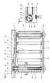
- the longitudinal conveyor 2 consists of a plurality of interacting individual conveyors 12, each of which has a length that closes the gap between conveyor elements 13 and the transverse conveyor 3.
- Each individual conveyor 12 consists of a frame 14 in which two shafts 15 and 16 are mounted, each of which carries a pair of sprockets 17.
- Two closed chains 18, which are arranged in pairs like the sprockets 17, are each guided by a sprocket 17 on the shaft 17 and a sprocket 17 on the shaft 16.
- These pairs of chains 18 carry sockets 19 for inserts 20 of a suitable material, in particular graphite.
- the frames 14 are provided with slide rails 21.
- the shaft 15 are extended on the side facing away from the cross conveyors 3 and carry a sprocket 22 on their shaft journals 15 a projecting from the frame 14.
- a closed chain 23 is arranged along the frame 14 and engages with the sprockets 22 of the individual conveyors 12 and connects them gears.
- the chain 23 is not one illustrated drive and provided on their one deflection 24 chain tensioner 25.
- a cover 26 for the chain 23, the chain wheels 22, the chain drive, the deflection wheel 24 and the chain tensioner 25 extends along the individual conveyors 12 and their frames 14.
- the conveyor elements 13 of the cross conveyor 3 protrude between the individual conveyors 12, so that the strands or strand sections accumulated on the individual conveyor 12 can be taken over by the conveying elements 13 for transverse transport on the cross conveyor 3 by vertical relative movement between the conveyor elements 13 and the individual conveyors.
- all of the individual conveyors 12 are fastened on a base frame 31 or groups (eight in the exemplary embodiment) of (in the exemplary embodiment four each) four individual conveyors 12 on interconnected base frames 31 with supports 32.
- Columns 34 are attached to the foundation 33, which guide the base frame or bases 31 so that they can move in the vertical direction.
- a base frame is supported by toggle lever 35, one of which lever part 35 a is variable in length for aligning the base frame 31 and for adjusting the conveying plane of the longitudinal conveyor 2 formed by the upper edges of the beams 19/20 to the conveying plane of the conveying elements 13 of the cross conveyor 3.
- the other lever part 35 b is connected to a lever 36.
- the levers 36 are connected to one another via a linkage 37 and via a further linkage 38 to an eccentric 39 of a drive 40.
- the linkage 37 is moved in the opposite direction to the arrow S, so that the conveying plane formed by the bars 19/20 passes over that of the conveying elements 13 and the longitudinal conveyor 2 for receiving another Stranges or strand section is available.
- the standard distance of the bars 19/20 along the pairs of chains 18 is exceeded by the fact that by submerging a bar 19/20 with the the sprockets 17 of a shaft 15 running chains 18 these beams 19/20 are not effective. So that there is no ejection or grinding of the strands on or on the conveyor elements 13 of the cross conveyor in these transition areas and this without having to choose the regular spacing of the bars 19/20 less than is otherwise required, the shafts 15 and 16 are between the sprockets 18 sockets 29 for inserts 30, i.e.
Applications Claiming Priority (2)
| Application Number | Priority Date | Filing Date | Title |
|---|---|---|---|
| DE19893936177 DE3936177A1 (de) | 1989-10-31 | 1989-10-31 | Im auslauf einer strangpresse angeordnete foerdereinrichtung |
| DE3936177 | 1989-10-31 |
Publications (2)
| Publication Number | Publication Date |
|---|---|
| EP0425869A2 true EP0425869A2 (fr) | 1991-05-08 |
| EP0425869A3 EP0425869A3 (en) | 1991-10-23 |
Family
ID=6392555
Family Applications (1)
| Application Number | Title | Priority Date | Filing Date |
|---|---|---|---|
| EP19900119642 Ceased EP0425869A3 (en) | 1989-10-31 | 1990-10-13 | Conveying device at the discharge end of an extrusion press |
Country Status (4)
| Country | Link |
|---|---|
| EP (1) | EP0425869A3 (fr) |
| JP (1) | JPH03165923A (fr) |
| CA (1) | CA2028778A1 (fr) |
| DE (1) | DE3936177A1 (fr) |
Cited By (4)
| Publication number | Priority date | Publication date | Assignee | Title |
|---|---|---|---|---|
| WO2002100564A1 (fr) * | 2001-06-11 | 2002-12-19 | Norsk Hydro Asa | Procede et equipement utiles pour calibrer des profiles extrudes |
| CN106800165A (zh) * | 2017-02-09 | 2017-06-06 | 慈溪市今日自动化科技有限公司 | 红煅物料加工系统 |
| CN110356823A (zh) * | 2019-07-24 | 2019-10-22 | 德屹智能科技(扬州)有限公司 | 一种换向升降输送机及输送系统 |
| CN113510913A (zh) * | 2021-07-15 | 2021-10-19 | 深圳市旭龙光电有限公司 | 一种光学级pmma板挤出机用接料装置 |
Families Citing this family (6)
| Publication number | Priority date | Publication date | Assignee | Title |
|---|---|---|---|---|
| DE19519574C1 (de) * | 1995-05-29 | 1996-10-10 | Koemmerling Kunststoff | Separiervorrichtung für Profile |
| EP0759331B1 (fr) * | 1995-08-12 | 1997-04-09 | SMS HASENCLEVER GmbH | Dispositif de transport transversal pas à pas de profilés entre une presse à extruder et une presseuse à tension |
| DE19600827A1 (de) * | 1996-01-12 | 1997-07-17 | Greiz Plasttechnik | Verfahren und Vorrichtung zum taktweisen Fördern von Formen auf einem horizontalen Umsetzertransportsystem |
| DE19728347A1 (de) * | 1997-07-03 | 1999-01-07 | Tul Log Ges Fuer Transport Ums | Segmentförderer |
| EP0959025A1 (fr) | 1998-05-20 | 1999-11-24 | SMS EUMUCO GmbH | Convoyeur à la sortie d'une presse d'extrusion |
| DE10241348B4 (de) * | 2002-09-06 | 2004-09-30 | Knapp Logistik Automation Ges.M.B.H. | Fördereinrichtung für den Transport von Stückgut vorzugsweise in einer Kommisionieranlage |
Citations (8)
| Publication number | Priority date | Publication date | Assignee | Title |
|---|---|---|---|---|
| US2993583A (en) * | 1958-06-03 | 1961-07-25 | Toronto Star Ltd | Roller slat conveyor diverter mechanism |
| GB1011618A (en) * | 1963-02-15 | 1965-12-01 | Johns Manville | Improvements in or relating to conveyor devices |
| FR1450053A (fr) * | 1965-10-06 | 1966-05-06 | Fielding & Platt Ltd | Transporteur notamment pour les presses à filer ainsi que les presses à filer pourvues de ce transporteur |
| US3271985A (en) * | 1964-01-14 | 1966-09-13 | Mueller Brass Co | Apparatus and method for straightening extruded bar stock |
| DE1300898B (de) * | 1961-06-28 | 1969-08-14 | Sack Gmbh Maschf | UEbergabevorrichtung fuer den aus einer Strangpresse ausgepressten Strang |
| US4174774A (en) * | 1978-01-30 | 1979-11-20 | Bourgeois Ronald D | Four-way diverting conveyor |
| US4790167A (en) * | 1987-06-23 | 1988-12-13 | Granco-Clark, Inc. | Extrusion run-out table |
| GB2224990A (en) * | 1988-11-22 | 1990-05-23 | Amada Co Ltd | Conveying workpiece to cutting machine |
Family Cites Families (2)
| Publication number | Priority date | Publication date | Assignee | Title |
|---|---|---|---|---|
| BE640430A (fr) * | 1963-02-15 | 1964-05-26 | ||
| FR2294773A1 (fr) * | 1974-12-18 | 1976-07-16 | Secim | Procede et installation de formation de nappes de barres |
-
1989
- 1989-10-31 DE DE19893936177 patent/DE3936177A1/de active Granted
-
1990
- 1990-10-13 EP EP19900119642 patent/EP0425869A3/de not_active Ceased
- 1990-10-29 CA CA 2028778 patent/CA2028778A1/fr not_active Abandoned
- 1990-10-31 JP JP2292216A patent/JPH03165923A/ja active Pending
Patent Citations (8)
| Publication number | Priority date | Publication date | Assignee | Title |
|---|---|---|---|---|
| US2993583A (en) * | 1958-06-03 | 1961-07-25 | Toronto Star Ltd | Roller slat conveyor diverter mechanism |
| DE1300898B (de) * | 1961-06-28 | 1969-08-14 | Sack Gmbh Maschf | UEbergabevorrichtung fuer den aus einer Strangpresse ausgepressten Strang |
| GB1011618A (en) * | 1963-02-15 | 1965-12-01 | Johns Manville | Improvements in or relating to conveyor devices |
| US3271985A (en) * | 1964-01-14 | 1966-09-13 | Mueller Brass Co | Apparatus and method for straightening extruded bar stock |
| FR1450053A (fr) * | 1965-10-06 | 1966-05-06 | Fielding & Platt Ltd | Transporteur notamment pour les presses à filer ainsi que les presses à filer pourvues de ce transporteur |
| US4174774A (en) * | 1978-01-30 | 1979-11-20 | Bourgeois Ronald D | Four-way diverting conveyor |
| US4790167A (en) * | 1987-06-23 | 1988-12-13 | Granco-Clark, Inc. | Extrusion run-out table |
| GB2224990A (en) * | 1988-11-22 | 1990-05-23 | Amada Co Ltd | Conveying workpiece to cutting machine |
Cited By (5)
| Publication number | Priority date | Publication date | Assignee | Title |
|---|---|---|---|---|
| WO2002100564A1 (fr) * | 2001-06-11 | 2002-12-19 | Norsk Hydro Asa | Procede et equipement utiles pour calibrer des profiles extrudes |
| CN106800165A (zh) * | 2017-02-09 | 2017-06-06 | 慈溪市今日自动化科技有限公司 | 红煅物料加工系统 |
| CN106800165B (zh) * | 2017-02-09 | 2022-05-17 | 慈溪市今日自动化科技有限公司 | 红煅物料加工系统 |
| CN110356823A (zh) * | 2019-07-24 | 2019-10-22 | 德屹智能科技(扬州)有限公司 | 一种换向升降输送机及输送系统 |
| CN113510913A (zh) * | 2021-07-15 | 2021-10-19 | 深圳市旭龙光电有限公司 | 一种光学级pmma板挤出机用接料装置 |
Also Published As
| Publication number | Publication date |
|---|---|
| CA2028778A1 (fr) | 1991-05-01 |
| DE3936177C2 (fr) | 1993-02-18 |
| EP0425869A3 (en) | 1991-10-23 |
| JPH03165923A (ja) | 1991-07-17 |
| DE3936177A1 (de) | 1991-05-02 |
Similar Documents
| Publication | Publication Date | Title |
|---|---|---|
| EP0156127B1 (fr) | Dispositif pour palettisation | |
| DE3107584C2 (fr) | ||
| EP0438109A2 (fr) | Dispositif pour découper en morceaux des blocs de produits alimentaires congelés | |
| DE3936177C2 (fr) | ||
| DE2411660B2 (de) | Vorrichtung zum kuehlen der pressunterlagen im zuge der herstellung von spanplatten, faserplatten u. dgl. | |
| DE2206137C3 (de) | Fördereinrichtung für das Zuführen von Stückwaren zu einer Zähl- und/ oder Verpackungsstation B Sprengel & Co, 3000 Hannover | |
| EP0597387A1 (fr) | Presse avec dispositif de transfert de tôles | |
| CH670809A5 (fr) | ||
| DE19925343A1 (de) | Transfereinrichtung | |
| DE3232180C2 (de) | Stapelvorrichtung für langgestrecktes Gut | |
| DE3024803A1 (de) | Transportvorrichtung, insbes. fuer verpackungsmaschinen | |
| DE1683849B1 (de) | Einrichtung zum Schneiden gegossener,in plastischem Zustand befindlicher Gasbetonbloecke | |
| CH689670A5 (de) | Foerderanlage mit einer das seitliche Herabfallen von Stueckguetern verhindernden Seitenfuehrung. | |
| DE3107438A1 (de) | "einrichtung zum zentrierenden ausrichten von plattenfoermigen werkstuecken" | |
| DE3901201A1 (de) | Ketten-speichervorrichtung | |
| DE4113479A1 (de) | Vorrichtung zum abstapeln von grossflaechigen, kontinuierlich anfallenden platten | |
| DE2547114A1 (de) | Verfahren und vorrichtung zum ueberfuehren von staeben von einer streckbank zu einem foerderer | |
| DE2938757A1 (de) | Lagervorrichtung | |
| DE2042733B2 (de) | Vorrichtung zum Quertransport und Übergabe von Strangpreßgut oder Walzgut, beispielsweise hinter einer Metallstrang presse | |
| DE10124224B4 (de) | Transportvorrichtung für Formkästen in einer Mogulanlage | |
| DE3242484C1 (de) | Transportvorrichtung fuer laengliche Werkstuecke | |
| DE19520107A1 (de) | Vakuum-Eingabegerät | |
| AT384800B (de) | Verteiltisch fuer plattenfoermige werkstuecke bzw. werkstueckpakete | |
| DE102017110210A1 (de) | Rollstangenzentriereinrichtung für eine Rollenteppichvorrichtung einer kontinuierlich arbeitenden Presse, Rollstangenteppichvorrichtung, kontinuierlich arbeitende Presse und Verfahren zur Zentrierung von Rollstangen eines Rollstangenteppichs | |
| DE2360998C2 (de) | Vorrichtung zum Entnehmen von aus band- bzw. streifenförmigem Material hergestellten Blechteilen aus Pressen |
Legal Events
| Date | Code | Title | Description |
|---|---|---|---|
| PUAI | Public reference made under article 153(3) epc to a published international application that has entered the european phase |
Free format text: ORIGINAL CODE: 0009012 |
|
| 17P | Request for examination filed |
Effective date: 19901013 |
|
| AK | Designated contracting states |
Kind code of ref document: A2 Designated state(s): AT BE CH DE ES FR GB IT LI NL |
|
| PUAL | Search report despatched |
Free format text: ORIGINAL CODE: 0009013 |
|
| AK | Designated contracting states |
Kind code of ref document: A3 Designated state(s): AT BE CH DE ES FR GB IT LI NL |
|
| 17Q | First examination report despatched |
Effective date: 19930205 |
|
| STAA | Information on the status of an ep patent application or granted ep patent |
Free format text: STATUS: THE APPLICATION HAS BEEN REFUSED |
|
| 18R | Application refused |
Effective date: 19940310 |