EP0423910B1 - Drucker, insbesondere Matrixnadeldrucker - Google Patents
Drucker, insbesondere Matrixnadeldrucker Download PDFInfo
- Publication number
- EP0423910B1 EP0423910B1 EP90250223A EP90250223A EP0423910B1 EP 0423910 B1 EP0423910 B1 EP 0423910B1 EP 90250223 A EP90250223 A EP 90250223A EP 90250223 A EP90250223 A EP 90250223A EP 0423910 B1 EP0423910 B1 EP 0423910B1
- Authority
- EP
- European Patent Office
- Prior art keywords
- printer
- guide
- drive motor
- frame
- printer according
- Prior art date
- Legal status (The legal status is an assumption and is not a legal conclusion. Google has not performed a legal analysis and makes no representation as to the accuracy of the status listed.)
- Expired - Lifetime
Links
Images


Classifications
-
- B—PERFORMING OPERATIONS; TRANSPORTING
- B41—PRINTING; LINING MACHINES; TYPEWRITERS; STAMPS
- B41J—TYPEWRITERS; SELECTIVE PRINTING MECHANISMS, i.e. MECHANISMS PRINTING OTHERWISE THAN FROM A FORME; CORRECTION OF TYPOGRAPHICAL ERRORS
- B41J29/00—Details of, or accessories for, typewriters or selective printing mechanisms not otherwise provided for
- B41J29/02—Framework
Definitions
- the invention relates to a printer, in particular a dot matrix printer, with a frame on which a pressure abutment extends in the longitudinal direction and opposite this there is a longitudinal guide for a carriage with a print head, with a paper guide for single sheets and / or an endless paper web, each by means of drive motors are drivable and controllable, the frame being enclosed by a two-part or multi-part plastic housing.
- printers In most cases, such printers have a metallic base frame and a two-part or multi-part plastic housing.
- the printer width is determined by the predetermined length of the platen and by the path of the printhead, which has to travel approximately the full length of the platen. This path is tailored to the printable width of the paper to be processed.
- the invention is therefore based on the object of being able to produce printers very simply and economically for different paper widths.
- the task is solved according to the invention in that the frame at the end of the paper guide or the pressure abutment or the longitudinal guide for the print head carriage forms a separate space in which at least one circuit board for the electronics , an interface board and the paper guide drive motor and the print head carriage drive motor are arranged.
- the advantage is that, in terms of production technology, all lengths of the pressure abutment, the longitudinal guide and the guide rods and axes that are suitable for this are simply lengthened or shortened in order to achieve a printer for a predetermined paper width. At the same time, the shortest possible connection lines result among the electrical or electronic assemblies.
- the stated object is also achieved according to the invention in that all parts of the printer frame, with the exception of metallic guide rods and axles, are made of plasticizable plastics and that all electrical or electronic components and their connecting elements are in a separate room are arranged.
- all parts of the printer frame with the exception of metallic guide rods and axles, are made of plasticizable plastics and that all electrical or electronic components and their connecting elements are in a separate room are arranged.
- the two solutions can be improved by shielding the separated space against interference radiation by means of a sheet metal housing that shields outwards.
- the two solutions are further developed by providing a frame wall made of electrically conductive plastic facing the paper guide or the pressure abutment or the longitudinal guide for the print head carriage, in which guide rods, axles and the like. are electrically conductive and the pressure abutment are mounted.
- a service simplification is that the interface board can be removed or reinserted in the lateral direction or to the rear along a guide.
- a more favorable division of space of the separated space is also achieved in that the electrical line connections for the paper guide drive motor or for the carriage drive motor are led to a circuit board arranged in the region of the side wall of the separated space for the power electronics.
- the network connection part is located on the back of the separated room. It is therefore outside the paper guideway and is easier to access than before even when the paper web is drawn in.
- control panel is arranged on the side of the shielded room.
- the shortest possible connection and supply lines also result here.
- buttons of the control panel protrude through openings in the removable plastic housing.
- a (serial) matrix printer of the needle print head type is shown as the printer.
- the invention can be applied to many types of printers regardless of the principle of dot-matrix printing.
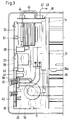
- the printer has a frame 1 made of metal or plastic, on which a pressure abutment 3 extends in the longitudinal direction 2 and, parallel to this, a longitudinal guide 4, consisting of a guide rod 5 and an axis 6 for a print head carriage 7 with a print head 8 .
- a paper guide 9 for single sheets and such a paper guide 9a for continuous paper webs are provided.
- the paper guides 9 and 9a can be driven and controlled by means of a paper guide drive motor 10 and a print head carriage drive motor 11.
- the entire unit with the frame 1 is enclosed in a two-part plastic housing 12 and keeps dust and dirt away from the interior and isolates pressure noises from the inside out.
- the frame 1 is then formed at the end 13 of the paper guides 9, 9a or at the end of the platen 3 or the longitudinal guide 4 for the print head carriage 7 as a separate space 14.
- At least one circuit board for the control electronics 15, an interface circuit board 16 and the paper guide drive motor 10 and the print head carriage drive motor 11 are arranged in this special space 14.
- All parts of the frame 1 with the exception of metallic guide rods 5 and axes 6 are made of plasticizable plastics. All electrical or electronic components and their Connecting elements are arranged in the separated room 14.
- the space 14 is surrounded by a sheet metal housing 17.
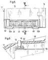
- the sheet metal housing 17 advantageously has a removable sheet metal cover 17a (FIG. 4).
- the interface board 16 can be easily removed together with its plug contact strip 18.
- One of the paper guides 9, 9a or the pressure abutment 3 or the longitudinal guide 4 for the print head carriage 7 facing the frame wall 1a is made of electrically conductive plastic (carbon fiber).
- the guide rod 5 and the axis 6 are mounted in an electrically conductive manner in this frame wall 1a.
- the pressure abutment 3 is also mounted in this frame wall 1a (electrically conductive).
- the electrical conductivity is used to derive electrostatic voltages that could affect the operating personnel.
- the room 14 shielded against interference radiation is divided into different floors 19 and 20, of which the upper floor 19 (FIG. 2) is formed from the boards for the control electronics 15 and the interface 16 and the lower floor 20 and others. is represented by the paper guide drive motor 10 and the print head carriage drive motor 11 (Fig. 3).
- the control logic board 15 and the interface board 16 are mechanically and electronically connected to one another by a connecting plug 21 (FIG. 2).
- the interface board 16 can, as shown in FIG. 2 by a position shown in dashed lines, be pulled laterally to the left first of a pawl 22 against a spring arm 24 and then from the connector 21 and further from a guide 23, which the spring arm 24 for Has releasable locking.
- the interface board 16 carries components, such as an EPROM 25, which contains a control program.
- the remaining components 26 to 34 form the necessary modules for the interface functions.
- the paper guide drive motor 10 is mounted on the frame wall 1a made of electrically conductive plastic.
- the electrical line connections 34a and 35 for the paper guide drive motor 10 and the electrical line connections 36 and 37 are led to a circuit board 38 for the power electronics.
- This power electronics board 38 is arranged on the outside of the separated space 14 under the sheet metal housing 17. Components such as a capacitor 39, memory chips 40, 41, driver chips 42 and the like are on the circuit board 38. intended.
- a mains connection part 43, a mains switch 44 and a mains plug 45 are located on the rear side 46 of the separated room 14.
- the plug contact strip 18 for the interface board 16 and the power cable 47 are also located on the rear side 46 of the separated space 14 and are therefore all freely accessible even when the paper web is inserted.
- a control panel 48 is arranged on the side of the shielded room 14 so that the control panel 48 can be located on the right or left of the printer.
- buttons 49 of the control panel 48 are guided through openings 50 of the removable plastic housing 12 and project accordingly, although on the lower floor 20 (FIG. 3) a mains transformer 51, the paper guide drive motor 10 and the print head carriage drive motor 11 are regarded as heat dissipation Need to become, sufficient heat can be dissipated to the environment outside the plastic housing 12 without forced ventilation through the highly heat-conductive sheet metal housing 17.
- the sheet metal housing 17 is also designed as a base plate (FIG. 4) and is in contact with the otherwise U-shaped jacket plate, the two legs of which form the front 52 and the rear 46 (FIG. 3).
- the sheet metal housing 17 is also equipped with bending protrusions 52a and 52b. 5 and 6, the individual button assemblies 53 and the support plate 54 receiving the buttons are also visible.
Landscapes
- Accessory Devices And Overall Control Thereof (AREA)
- Superconductors And Manufacturing Methods Therefor (AREA)
- Character Spaces And Line Spaces In Printers (AREA)
- Pharmaceuticals Containing Other Organic And Inorganic Compounds (AREA)
Applications Claiming Priority (2)
| Application Number | Priority Date | Filing Date | Title |
|---|---|---|---|
| DE3934792 | 1989-10-16 | ||
| DE3934792A DE3934792A1 (de) | 1989-10-16 | 1989-10-16 | Drucker, insbesondere matrixnadeldrucker |
Publications (3)
| Publication Number | Publication Date |
|---|---|
| EP0423910A2 EP0423910A2 (de) | 1991-04-24 |
| EP0423910A3 EP0423910A3 (en) | 1991-10-16 |
| EP0423910B1 true EP0423910B1 (de) | 1994-03-23 |
Family
ID=6391729
Family Applications (1)
| Application Number | Title | Priority Date | Filing Date |
|---|---|---|---|
| EP90250223A Expired - Lifetime EP0423910B1 (de) | 1989-10-16 | 1990-09-06 | Drucker, insbesondere Matrixnadeldrucker |
Country Status (5)
| Country | Link |
|---|---|
| US (1) | US5152624A (https=) |
| EP (1) | EP0423910B1 (https=) |
| JP (1) | JPH03133680A (https=) |
| AT (1) | ATE103243T1 (https=) |
| DE (3) | DE3943567A1 (https=) |
Families Citing this family (9)
| Publication number | Priority date | Publication date | Assignee | Title |
|---|---|---|---|---|
| US5863141A (en) * | 1996-07-22 | 1999-01-26 | Hewlett-Packard Company | Image-related device with printed-circuit assembly cantilevered from sheet-metal base & with clip fastenings |
| US6357859B1 (en) * | 1997-09-23 | 2002-03-19 | Eastman Kodak Company | Printer and method with an electromagnetic-inhibiting optical data link transmitting image forming data |
| FR2845943B1 (fr) * | 2002-10-19 | 2005-02-11 | Denis Montagutelli | Imprimante modulaire pour, a partir d'une imprimante de base, composer une imprimante de bureau, et/ou de panneau et/ou portable |
| US7938531B2 (en) | 2006-09-27 | 2011-05-10 | Lexmark International, Inc. | Methods and apparatus for handheld printing with optical positioning |
| US7748840B2 (en) * | 2006-09-27 | 2010-07-06 | Lexmark International, Inc. | Methods and apparatus for handheld printing with optical positioning |
| US7918519B2 (en) | 2006-09-27 | 2011-04-05 | Lexmark International, Inc. | Methods and apparatus for handheld printing with optical positioning |
| US8092006B2 (en) | 2007-06-22 | 2012-01-10 | Lexmark International, Inc. | Handheld printer configuration |
| US20090040286A1 (en) * | 2007-08-08 | 2009-02-12 | Tan Theresa Joy L | Print scheduling in handheld printers |
| JP5939089B2 (ja) * | 2012-08-31 | 2016-06-22 | セイコーエプソン株式会社 | インクジェット記録装置 |
Family Cites Families (21)
| Publication number | Priority date | Publication date | Assignee | Title |
|---|---|---|---|---|
| DE2136806A1 (de) * | 1971-07-23 | 1973-02-01 | Olympia Werke Ag | Gehaeuse fuer schreib-, buchungs- oder aehnliche maschinen |
| DE2203981C3 (de) * | 1972-01-28 | 1975-12-04 | Olympia Werke Ag, 2940 Wilhelmshaven | Verkleidung für Schreib- und ähnliche Büromaschinen |
| DE2335735A1 (de) * | 1973-07-13 | 1975-01-30 | Forster Electronic Gmbh | Textbearbeitungsgeraet fuer fernsteuerbare schreibmaschinen |
| DE7927378U1 (de) * | 1979-09-27 | 1980-01-24 | Triumph Werke Nuernberg Ag, 8500 Nuernberg | Gestell fuer schreib- o.ae. maschinen |
| US4370515A (en) * | 1979-12-26 | 1983-01-25 | Rockwell International Corporation | Electromagnetic interference |
| IT1144422B (it) * | 1981-07-23 | 1986-10-29 | Olivetti & Co Spa | Dispositivo per schermare circuiti elettrici |
| US4527285A (en) * | 1982-03-29 | 1985-07-02 | International Business Machines Corporation | Pluggable terminal architecture |
| US4549825A (en) * | 1983-02-08 | 1985-10-29 | Post Technologies, Inc. | Thermal printer for a low cost electronic mail terminal |
| JPS6019577A (ja) * | 1983-07-14 | 1985-01-31 | Matsushita Electric Ind Co Ltd | 印字装置 |
| DK445184D0 (da) * | 1984-09-18 | 1984-09-18 | Storno As | Elektronisk apparat, elektronisk komponent samt fremgangsmaade til fremstilling af et saadant apparat og en saadan komponent |
| US4732502A (en) * | 1984-11-19 | 1988-03-22 | Brother Kogyo Kabushiki Kaisha | Printer |
| US4730947A (en) * | 1985-08-19 | 1988-03-15 | Citizen Watch Co., Ltd. | Printer having a control circuit section of cassette type |
| JPS63139774A (ja) * | 1986-12-02 | 1988-06-11 | Brother Ind Ltd | プリンタ |
| DE3752179T2 (de) * | 1986-12-10 | 1998-08-20 | Canon Kk | Aufzeichnungsgerät und Entladungsregeneriermethode |
| US4883376A (en) * | 1987-01-06 | 1989-11-28 | Brother Kogyo Kabushiki Kaisha | Data processing apparatus with CRT and printer |
| JPS63108752U (https=) * | 1987-01-06 | 1988-07-13 | ||
| JPS63183868A (ja) * | 1987-01-27 | 1988-07-29 | Tokyo Electric Co Ltd | 印字装置 |
| JPS63197682A (ja) * | 1987-02-13 | 1988-08-16 | Hitachi Ltd | パ−ソナルワ−ドプロセツサ |
| JP2613431B2 (ja) * | 1988-05-18 | 1997-05-28 | キヤノン株式会社 | シリアル記録装置 |
| US4881839A (en) * | 1988-06-14 | 1989-11-21 | Texas Instruments Incorporated | Portable electronic data handling/data entry system |
| JP3082348B2 (ja) * | 1991-09-13 | 2000-08-28 | 株式会社ユアサコーポレーション | ニッケル−水素電池 |
-
1989
- 1989-10-16 DE DE19893943567 patent/DE3943567A1/de active Pending
- 1989-10-16 DE DE3934792A patent/DE3934792A1/de active Granted
-
1990
- 1990-09-06 EP EP90250223A patent/EP0423910B1/de not_active Expired - Lifetime
- 1990-09-06 AT AT90250223T patent/ATE103243T1/de not_active IP Right Cessation
- 1990-09-06 DE DE90250223T patent/DE59005089D1/de not_active Expired - Fee Related
- 1990-10-12 JP JP2275159A patent/JPH03133680A/ja active Pending
- 1990-10-15 US US07/597,731 patent/US5152624A/en not_active Expired - Fee Related
Also Published As
| Publication number | Publication date |
|---|---|
| US5152624A (en) | 1992-10-06 |
| DE3934792A1 (de) | 1991-04-25 |
| ATE103243T1 (de) | 1994-04-15 |
| JPH03133680A (ja) | 1991-06-06 |
| EP0423910A2 (de) | 1991-04-24 |
| DE3943567A1 (de) | 1991-06-20 |
| DE59005089D1 (de) | 1994-04-28 |
| EP0423910A3 (en) | 1991-10-16 |
| DE3934792C2 (https=) | 1991-09-12 |
Similar Documents
| Publication | Publication Date | Title |
|---|---|---|
| DE68916364T2 (de) | Scherkraftübertrager für tintenstrahlsysteme. | |
| AT392386B (de) | Elektronisches geraet | |
| DE2742643C2 (de) | Modulaufbau für ein elektronisches Datenverarbeitungsgerät | |
| DE1590532B2 (de) | Kontaktfederleiste | |
| EP0423910B1 (de) | Drucker, insbesondere Matrixnadeldrucker | |
| EP0013335A1 (de) | Anordnung zum elektrischen Verbinden einer Vielzahl von Anschlüssen | |
| DE3414920A1 (de) | Tastenfeld | |
| DE2822847A1 (de) | Kapazitaetsgekoppelte tafel | |
| DE3226510C2 (de) | Universelle Papiertransporteinrichtung für Einzelblätter und Endlospapier in Zeilendruckeinrichtungen | |
| DE3725334A1 (de) | Punktdrucker | |
| DE3854593T2 (de) | Elektrische Steckverbindung, am Kabelende angeschlossen und ausgestattet mit Mitteln zur Verringerung der Zugkraft, die auf das Kabel und durch das Kabel wirkt. | |
| DE1060951B (de) | Kontaktleiste | |
| DE3032858A1 (de) | Druckvorrichtung | |
| DE69122846T2 (de) | Verbinder für die Kupplung eines Druckkopfes mit einer Schaltung in einem Drucker | |
| DE1209330B (de) | Signalgeber fuer eine Programmsteuerung | |
| DE69423406T2 (de) | Einrichtung für den Anschluss eines Schlittens | |
| DE2844576A1 (de) | Baugruppentraeger | |
| DE2852352C2 (de) | Elektrostatischer Druckkopf | |
| DE3142937C2 (de) | Handstempel mit einem elektrisch oder elektronisch steuerbaren Nadeldruckwerk | |
| EP0040883A2 (de) | Matrixdrucker mit magnetischer Druckkopfeinstellung | |
| EP0320048B1 (de) | Büromaschine mit einem Papiervorratsmagazin | |
| DE2253470A1 (de) | Druckerkopfbaugruppe fuer punktmatrixschnelldrucker | |
| DE2309763A1 (de) | Ablenkelektrodenanordnung und verfahren zu ihrer herstellung | |
| DE3931190A1 (de) | Bueromaschine, z. b. drucker | |
| DE2845204C2 (de) | Textkarte für in Baugruppenträger einschiebbare Baugruppen |
Legal Events
| Date | Code | Title | Description |
|---|---|---|---|
| PUAI | Public reference made under article 153(3) epc to a published international application that has entered the european phase |
Free format text: ORIGINAL CODE: 0009012 |
|
| AK | Designated contracting states |
Kind code of ref document: A2 Designated state(s): AT BE CH DE FR GB IT LI NL |
|
| PUAL | Search report despatched |
Free format text: ORIGINAL CODE: 0009013 |
|
| AK | Designated contracting states |
Kind code of ref document: A3 Designated state(s): AT BE CH DE FR GB IT LI NL |
|
| 17P | Request for examination filed |
Effective date: 19911126 |
|
| 17Q | First examination report despatched |
Effective date: 19930712 |
|
| GRAA | (expected) grant |
Free format text: ORIGINAL CODE: 0009210 |
|
| AK | Designated contracting states |
Kind code of ref document: B1 Designated state(s): AT BE CH DE FR GB IT LI NL |
|
| PG25 | Lapsed in a contracting state [announced via postgrant information from national office to epo] |
Ref country code: IT Free format text: LAPSE BECAUSE OF FAILURE TO SUBMIT A TRANSLATION OF THE DESCRIPTION OR TO PAY THE FEE WITHIN THE PRESCRIBED TIME-LIMIT;WARNING: LAPSES OF ITALIAN PATENTS WITH EFFECTIVE DATE BEFORE 2007 MAY HAVE OCCURRED AT ANY TIME BEFORE 2007. THE CORRECT EFFECTIVE DATE MAY BE DIFFERENT FROM THE ONE RECORDED. Effective date: 19940323 Ref country code: BE Effective date: 19940323 Ref country code: NL Effective date: 19940323 |
|
| REF | Corresponds to: |
Ref document number: 103243 Country of ref document: AT Date of ref document: 19940415 Kind code of ref document: T |
|
| REF | Corresponds to: |
Ref document number: 59005089 Country of ref document: DE Date of ref document: 19940428 |
|
| ET | Fr: translation filed | ||
| GBT | Gb: translation of ep patent filed (gb section 77(6)(a)/1977) |
Effective date: 19940621 |
|
| PGFP | Annual fee paid to national office [announced via postgrant information from national office to epo] |
Ref country code: GB Payment date: 19940815 Year of fee payment: 5 |
|
| PGFP | Annual fee paid to national office [announced via postgrant information from national office to epo] |
Ref country code: FR Payment date: 19940819 Year of fee payment: 5 |
|
| PG25 | Lapsed in a contracting state [announced via postgrant information from national office to epo] |
Ref country code: AT Effective date: 19940906 |
|
| NLV1 | Nl: lapsed or annulled due to failure to fulfill the requirements of art. 29p and 29m of the patents act | ||
| PG25 | Lapsed in a contracting state [announced via postgrant information from national office to epo] |
Ref country code: LI Effective date: 19940930 Ref country code: CH Effective date: 19940930 |
|
| PLBE | No opposition filed within time limit |
Free format text: ORIGINAL CODE: 0009261 |
|
| STAA | Information on the status of an ep patent application or granted ep patent |
Free format text: STATUS: NO OPPOSITION FILED WITHIN TIME LIMIT |
|
| 26N | No opposition filed | ||
| REG | Reference to a national code |
Ref country code: CH Ref legal event code: PL |
|
| PG25 | Lapsed in a contracting state [announced via postgrant information from national office to epo] |
Ref country code: GB Effective date: 19950906 |
|
| GBPC | Gb: european patent ceased through non-payment of renewal fee |
Effective date: 19950906 |
|
| PG25 | Lapsed in a contracting state [announced via postgrant information from national office to epo] |
Ref country code: FR Effective date: 19960531 |
|
| REG | Reference to a national code |
Ref country code: FR Ref legal event code: ST |
|
| PGFP | Annual fee paid to national office [announced via postgrant information from national office to epo] |
Ref country code: DE Payment date: 19991005 Year of fee payment: 10 |
|
| PG25 | Lapsed in a contracting state [announced via postgrant information from national office to epo] |
Ref country code: DE Free format text: LAPSE BECAUSE OF NON-PAYMENT OF DUE FEES Effective date: 20010601 |