EP0419758B1 - Ladevorrichtung für modulare Treibladung - Google Patents
Ladevorrichtung für modulare Treibladung Download PDFInfo
- Publication number
- EP0419758B1 EP0419758B1 EP90108173A EP90108173A EP0419758B1 EP 0419758 B1 EP0419758 B1 EP 0419758B1 EP 90108173 A EP90108173 A EP 90108173A EP 90108173 A EP90108173 A EP 90108173A EP 0419758 B1 EP0419758 B1 EP 0419758B1
- Authority
- EP
- European Patent Office
- Prior art keywords
- loading
- fact
- accordance
- loading device
- driver
- Prior art date
- Legal status (The legal status is an assumption and is not a legal conclusion. Google has not performed a legal analysis and makes no representation as to the accuracy of the status listed.)
- Expired - Lifetime
Links
- 238000006073 displacement reaction Methods 0.000 claims description 15
- 230000001141 propulsive effect Effects 0.000 claims 3
- 239000003380 propellant Substances 0.000 description 17
- 238000000034 method Methods 0.000 description 6
- 230000001681 protective effect Effects 0.000 description 2
- 238000010276 construction Methods 0.000 description 1
- 238000011109 contamination Methods 0.000 description 1
- 210000003746 feather Anatomy 0.000 description 1
Images


Classifications
-
- F—MECHANICAL ENGINEERING; LIGHTING; HEATING; WEAPONS; BLASTING
- F41—WEAPONS
- F41A—FUNCTIONAL FEATURES OR DETAILS COMMON TO BOTH SMALLARMS AND ORDNANCE, e.g. CANNONS; MOUNTINGS FOR SMALLARMS OR ORDNANCE
- F41A9/00—Feeding or loading of ammunition; Magazines; Guiding means for the extracting of cartridges
- F41A9/38—Loading arrangements, i.e. for bringing the ammunition into the firing position
- F41A9/39—Ramming arrangements
- F41A9/42—Rammers separate from breech-block
-
- F—MECHANICAL ENGINEERING; LIGHTING; HEATING; WEAPONS; BLASTING
- F41—WEAPONS
- F41A—FUNCTIONAL FEATURES OR DETAILS COMMON TO BOTH SMALLARMS AND ORDNANCE, e.g. CANNONS; MOUNTINGS FOR SMALLARMS OR ORDNANCE
- F41A9/00—Feeding or loading of ammunition; Magazines; Guiding means for the extracting of cartridges
- F41A9/01—Feeding of unbelted ammunition
- F41A9/06—Feeding of unbelted ammunition using cyclically moving conveyors, i.e. conveyors having ammunition pusher or carrier elements which are emptied or disengaged from the ammunition during the return stroke
- F41A9/09—Movable ammunition carriers or loading trays, e.g. for feeding from magazines
- F41A9/10—Movable ammunition carriers or loading trays, e.g. for feeding from magazines pivoting or swinging
- F41A9/13—Movable ammunition carriers or loading trays, e.g. for feeding from magazines pivoting or swinging in a vertical plane
Definitions
- the invention relates to a charging device for modular propellant charge according to the features specified in the preamble of the patent claim.
- Such a loading device is known from DE-34 37 588 A1.
- This loading device is able to pivot propellant charge modules from a transfer position, which is located on the side next to the weapon barrel, to behind the base of the gun barrel.
- This document does not show a way of automatically feeding the propellant charge modules to the cargo space through an existing and downward-pointing loading trough of the base piece.
- the object of the invention is to provide a loading device which not only automatically swivels propellant charge modules received laterally next to the weapon barrel around the transfer arm which can be pivoted about the shield pin axis, but also automatically and safely guides them from the position behind the base piece through the free space of the base piece loading trough, which is preferably open at the bottom to the cargo area.
- the loading device not only allows the propellant charge modules to be automatically fed behind the base piece in successive transport movements, but also enables axial displacement of the entire swivel arm that can be rotated around the transfer arm and thus also axial displacement of the charging cradle in a particularly simple manner by arranging a displacement device through the free space of the floor loading trough to immediately behind the weapon barrel to the cargo area.
- the propellant charge modules located on the charging cradle are now securely guided by the longitudinal displacement of the charging cradle in the area of a loading trough of the base piece, which is preferably open at the bottom, and are supported in a stable manner downward in particular, and are briefly automatically pushed into the cargo space by a transport device in the advanced position of the charging cradle in the cargo space .
- the displacement direction is designed as part of the transfer arm pivotable about the vertical direction axis results in a particularly space-saving arrangement, so that an additional space requirement for accommodating the displacement device is unnecessary.
- the shifting device is constructed telescopically and shifts the swivel arm in the longitudinal direction parallel to the charging cradle and thus also the charging cradle via a motor-driven spindle drive, whereby on the one hand a robust drive mechanism is provided and on the other hand a precise control of the charging cradle on the front wall of the gun barrel cargo space is possible.
- a lifting tube of the displacement device that is movable by the spindle drive is connected on the inside to the shaft of a drive motor, wherein this drive motor is mounted on the outside of the lifting tube and thus generates the rotational movement of the charging cradle around the transfer arm by rotating its motor housing in a particularly simple and space-saving manner.
- the charging cradle is designed to be closed in the circumferential direction as a tube, as a result of which, on the one hand, a simple construction and, on the other hand, the propellant charge modules can be protected and safely fed to the cargo space.
- the transport device can also be arranged directly on the charging cradle in a space-saving manner between the webs of the swivel arm, as a result of which a threaded spindle can be driven in a short way for the supply process of the propellant charge modules.
- a driver that can be moved by the threaded spindle allows the feed movement for the propellant charge modules to be initiated gently.
- the carrier enables the charging cradle to be loaded easily because during loading the propellant charge modules pivot the carrier away in the loading direction by means of a joint and, after the charging process has ended, the latter can automatically be pivoted back into the region of the charging cradle for the further transport of the propellant charge modules into the cargo space.
- the driver is advantageously guided stably in the entrained position by lateral longitudinal guides.
- FIG. 1 illustrates a base piece 18 of a gun, not shown, which is connected to a gun barrel 14 and whose cargo space 32, which begins on the rear gun barrel side 26, can be closed by a vertically closing wedge 19.
- the base piece 18 contains a downward-facing free space behind the closure guide as a loading trough 24.
- the gun contains a height adjustment axis 12 of the weapon barrel 14 shown in FIGS. 2 and 3 and mounted on the armored turret housing 11, around which a transfer arm 16 for the transport of propellant charge modules 10 is arranged from a removal position located laterally next to the weapon barrel to the height adjustment position of the weapon barrel.
- a part of the transfer arm 16 is designed as a sliding device 30 movable in the axial direction 29 of a charging cradle 20 which can be pivoted about this sliding device 30, as a result of which the charging cradle 20 from the position 22 behind the base piece 18 through the loading trough 24 a distance S can be moved to a position 23 lying on the rear side of the weapon barrel loading space 32.
- the pivoting movement about the displacement device 30 takes place by means of a drive motor 52 fastened to the movable part of the displacement device 30, the housing 49 of which is connected to a loading shell 20 designed as a tube via a pivot arm 50 consisting of webs 51.
- a transport device 34 arranged on the outside of the charging cradle moves in the position 23 of the charging cradle 20, which is advanced by the displacement device 30 on the elongated barrel core axis 28 to the rear 26 of the weapon barrel 14, via a spindle drive 62, a driver 60 through which the propellant charge modules 10 located on the charging cradle 20 be transported into the cargo space 32.
- the displacement device 36 is mounted in a holding tube 46 which is connected in the longitudinal outer region to a web-shaped original part of the transfer arm 16 parallel to the charging cradle 20.
- a spindle drive 36 is fastened to the holding tube 46, which comprises a flanged motor 37, a threaded spindle 42 which is fixedly mounted in the holding tube and driven by the motor 37, and a lifting tube 38 which is axially displaceable by the threaded spindle 42, the lifting tube 38 is connected on the inside to a bushing 39, which is provided with an internal thread 40 for receiving the threaded spindle 42.
- the lifting tube 38 can be moved parallel to the charging cradle 20 by the spindle drive 37, 42, 39, the lifting tube 38 contains longitudinal guides 44 on the outside, which can be arranged as simple or as multi-spline connections between the lifting tube 38 and the inside 47 of the holding tube 46.
- the lifting tube 38 contains at the end facing away from the holding tube 46 on the outside a bearing 48 for fixing the Lifting tube 38 pivotable arm 50 and inside a drive motor 52 for performing the pivoting movement of the arm 50 in the direction 54.
- the drive motor 52 is permanently connected on the outside to a bearing housing 49 which can be rotated about the bearing 48, while the internal motor shaft 49 is connected non-rotatably to the lifting tube 38 via a feather key or multi-spline connection 55.
- a protective tube 45 is provided which is connected to the bearing housing 49 on one side and slides along the outside of the holding tube 46 on the other side.
- the charging cradle 20 is designed as a tube and is connected to the bearing housing 49 of the motor 52 which performs the swiveling movement in the direction 54 via the swivel arm 50.
- the latter consists of webs 51 connected tangentially to the charging cradle 20 and to the bearing housing 49.
- the transport device 34 is arranged on the outside of the tubular charging cradle 20 and comprises its own drive unit 56 and a driver 60, 61 which can be driven thereby for feeding the propellant charge modules 10 located on the charging cradle in the direction 58 directly into the cargo space 32.
- the drive unit 46 comprises a further drive motor 57 arranged between the webs 51 and a chain or belt drive 59 for driving a threaded spindle 62 mounted below the charging cradle 20, which in turn for the longitudinal displacement of the driver 60, 61 the driver 60 itself or a sliding block 66 another Driven driver 61 drives.
- the driver 60 can by a curve, not shown, for the charging process of the charging cradle 20 to be carried out is pivoted from the feed position 63 into a position 65 outside the charging cradle 20.
- the driver 61 is connected via a hinge 64 to the sliding block 66 arranged on the threaded spindle 62 and can thus be pivoted down from the driving position 63 when the propellant charge modules 10 are being charged from the area of the charging cradle 20 and then automatically again after the charging process has ended swing back.
- the driver 60, 61 and / or the sliding block 66 are laterally supported in longitudinal guides 68 to achieve a linear feed movement, which may consist of a longitudinal recess in the charging cradle 20 or additionally, for example, of simple angle profiles.
- the spindle drive 62, 66 located under the charging cradle 20 is protected on the outside by a protective hood 67 against contamination.
- the movement of the loading device takes place in the following steps: after the loading process of the loading shell 20, the transfer arm 16 swivels into the position corresponding to the barrel elevation of the weapon barrel. In this position, the motor 52 pivots the loading arm 50 in the direction 54 about the transfer arm 16 or about the axis of the holding and lifting tube 46, 38 up to the extended tube core axis 28 behind the base piece 18.
- the motor 37 moves via the spindle drive 36 the charging cradle 20 on the tube core axis 28 from the rear position 22 through the loading trough 24 of the base piece to the front position 23 to the rear 26 of the cargo space 32.
Landscapes
- Engineering & Computer Science (AREA)
- General Engineering & Computer Science (AREA)
- Replacement Of Web Rolls (AREA)
- Filling Or Discharging Of Gas Storage Vessels (AREA)
- Portable Nailing Machines And Staplers (AREA)
- Forklifts And Lifting Vehicles (AREA)
Description
- Die Erfindung betrifft eine Ladevorrichtung für modulare Treibladung nach den im Oberbegriff des Patenanspruchs angegebenen Merkmalen.
- Eine derartige Ladevorrichtung ist aus der DE-34 37 588 A1 als bekannt zu entnehmen. Diese Ladevorrichtung ist in der Lage, Treibladungsmodule aus einer seitlich neben dem Waffenrohr vorhandenen Übergabeposition bis hinter das Bodenstück des Waffenrohres zu schwenken. Aus dieser Druckschrift wird kein Weg aufgezeigt, die Treibladungsmodule geführt durch eine vorhandene und nach untenweisende Lademulde des Bodenstückes hindurch automatisch dem Ladungsraum zuzuführen.
- Aufgabe der Erfindung ist es, eine Ladevorrichtung bereitzustellen, die seitlich neben dem Waffenrohr aufgenommene Treibladungsmodule nicht nur automatisch um den um die Schildzapfenachse schwenkbarer Transferarm herumschwenkt, sondern sie aus der Position hinter dem Bodenstück automatisch und sicher geführt durch den vorzugsweise unten offenen Freiraum der Bodenstücklademulde hindurch dem Ladungsraum zuführt.
- Gelöst wird diese Aufgabe durch die im kennzeichnenden Teil des Patentanspruchs 1 angegebenen Merkmale. Vorteilhafte Ausgestaltungen der Erfindung gehen aus den Merkmalen der Unteransprüche hervor.
- Die Ladevorrichtung gestattet in nacheinander automatisch ablaufenden Transportbewegungen nicht nur eine automatische Zuführung der Treibladungsmodule hinter das Bodenstück, sondern ermöglicht durch die Anordnung einer Verschiebevorrichtung auf besonders einfache Weise auch einen axialen Verschub des gesamten um den Transferarm drehbaren Schwenkarmes und somit auch einen gleichzeitigen axialen Verschub der Ladeschale durch den Freiraum der Bodenstücklademulde hindurch bis unmittelbar hinter das Waffenrohr zum Ladungsraum. Die auf der Ladeschale befindlichen Treibladungsmodule werden durch die Längsverschiebung der Ladeschale nunmehr im Bereich einer vorzugsweise nach unten offenen Lademulde des Bodenstückes sicher geführt und insbesondere nach unten stabil abgestützt sowie in der vorgeschobenen am Ladungsraum anliegenden Position der Ladeschale kurzzeitig automatisch durch eine Transportvorrichtung in den Ladungsraum geschoben.
- Dadurch, daß die Verschieberichtung als Teil des um die Höhenrichtachse schwenkbaren Transferarmes ausgebildet ist, resultiert eine besonders raumsparende Anordnung, so daß ein zusätzlicher Raumbedarf zur Unterbringung der Verschiebevorrichtung entbehrlich ist.
- Die Verschiebevorrichtung ist teleskopartig aufgebaut und verschiebt in Längsrichtung parallel zur Ladeschale den Schwenkarm und somit auch die Ladeschale über einen motorisch antreibbaren Spindeltrieb, wodurch einerseits ein robuster Antriebsmechanismus bereitgestellt wird, andererseits eine präzise Ansteuerung der Ladeschale an die Stirnwand des Waffenrohrladungsraumes möglich ist.
- Nach einem weiteren Ausgestaltungsmerkmal ist ein von dem Spindeltrieb bewegbares Hubrohr der Verschiebevorrichtung innenseitig mit der Welle eines Antriebsmotors verbunden, wobei dieser Antriebsmotor außenseitig auf dem Hubrohr gelagert ist und somit durch eine Drehung seines Motorgehäuses auf besonders einfache und raumsparende Weise die Rotationsbewegung der Ladeschale um den Transferarm erzeugt.
- Die Ladeschale ist in Umfangsrichtung geschlossen als Rohr ausgeführt, wodurch einerseits eine einfache Bauweise und andererseits die Treibladungsmodule geschützt und sicher dem Ladungsraum zugeführt werden können.
- Nach einem weiteren Ausgestaltungsmerkmal kann die Transportvorrichtung unmittelbar an der Ladeschale des weiteren raumsparend zwischen den Stegen des Schwenkarmes angeordnet sein, wodurch auf kurzem Wege eine Gewindespindel für den Zuführvorgang der Treibladungsmodule angetrieben werden kann. Ein von der Gewindespindel verschiebbarer Mitnehmer gestattet ein schonendes Einleiten der Zuführbewegung für die Treibladungsmodule. Der Mitnehmer ermöglicht nach einem weiteren Ausgestaltungsmerkmal eine einfache Beladung der Ladeschale, weil während des Beladens die Treibladungsmodule den Mitnehmer durch ein Gelenk in Beladerichtung wegschwenken und dieser nach beendetem Ladevorgang automatisch in den Bereich der Ladeschale für den Weitertransport der Treibladungsmodule in den Ladungsraum zurückschwenkbar ist. Der Mitnehmer wird während der Zuführbewegung der Treibladungsmodule in den Ladungsraum weiter vorteilhaft stabil in der Mitnahmestellung durch seitliche Längsführungen geführt.
- Die Erfindung wird anhand eines in den Zeichnungen dargestellten Ausführungsbeispieles des näheren erläutert.
- Es zeigt:
- Figur 1
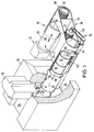
- die Ladevorrichtung mit dem Bodenstück eines Waffenrohres in einer perspektivischen Darstellung,
- Figur 2
- die Ladevorrichtung in einem durch den Transferarm verlaufenden Längsschnitt,
- Figur 3
- einen in der Figur 2 mit III-III gekennzeichneten Schnittverlauf,
- Figur 4
- einen in der Figur 2 mit IV-IV gekennzeichneten Schnittverlauf,
- Figur 5
- eine variierte Ausführungsmöglichkeit des in der Figur 4 im Bereich 5 dargestellten Mitnehmers,
- Figur 6
- einen in der Figur 5 mit VI-VI gekennzeichneten Schnittverlauf.
- Die Figur 1 verdeutlicht ein mit einem Waffenrohr 14 verbundenes Bodenstück 18 eines nicht näher dargestellten Geschützes, dessen auf der hinteren Waffenrohrseite 26 beginnender Ladungsraum 32 durch einen senkrecht schließenden Verschlußkeil 19 schließbar ist. Das Bodenstück 18 enthält hinter der Verschlußführung einen nach unten weisenden Freiraum als Lademulde 24.
- Das Geschütz enthält eine in den Figuren 2 und 3 dargestellte und am Panzerturmgehäuse 11 gelagerte Höhenrichtachse 12 des Waffenrohres 14, um die ein Transferarm 16 für den Transport von Treibladungsmodulen 10 aus einer seitlich neben dem Waffenrohr befindlichen Entnahmeposition bis zur Höhenrichtposition des Waffenrohres angeordnet ist.
- Ein Teil des Transferarmes 16 ist als eine in axialer Richtung 29 bewegbare Verschiebevorrichtung 30 einer um diese Verschiebevorrichtung 30 schwenkbaren Ladeschale 20 ausgebildet, wodurch die Ladeschale 20 aus der Position 22 hinter dem Bodenstück 18 durch die Lademulde 24 hindurch über eine Wegstrecke S bis zu einer an der Hinterseite des Waffenrohrladungsraumes 32 anliegenden Position 23 bewegt werden kann. Die Schwenkbewegung um die Verschiebevorrichtung 30 erfolgt durch einen am beweglichen Teil der Verschiebevorrichtung 30 befestigten Antriebsmotor 52, dessen Gehäuse 49 über einen aus Stegen 51 bestehenden Schwenkarm 50 mit einer als Rohr ausgebildeten Ladeschale 20 verbunden ist.
- Eine außenseitig der Ladeschale angeordnete Transportvorrichtung 34 bewegt in der durch die Verschiebevorrichtung 30 auf der verlängerten Rohrseelenachse 28 bis zur Hinterseite 26 des Waffenrohres 14 vorgezogenen Position 23 der Ladeschale 20 über einen Spindeltrieb 62 einen Mitnehmer 60, durch den die auf der Ladeschale 20 befindlichen Treibladungsmodule 10 in den Ladungsraum 32 transportiert werden.
- Die Verschiebevorrichtung 36 ist in einem Halterohr 46 gelagert, welches im längsseitigen Außenbereich mit einem stegförmig ausgebildeten ursprünglichen Teil des Transferarmes 16 parallel zur Ladeschale 20 verbunden ist. Auf der der Höhenrichtachse 12 benachtarten Seite ist am Halterohr 46 ein Spindelantrieb 36 befestigt, der einen angeflanschten Motor 37, eine fest im Halterohr gelagerte und vom Motor 37 angetriebene Gewindespindel 42 und ein von der Gewindespindel 42 axial verschiebbares Hubrohr 38 umfaßt, wobei das Hubrohr 38 innenseitig mit einer Buchse 39 verbunden ist, welche mit einem Innengewinde 40 zur Aufnahme der Gewindespindel 42 versehen ist. Damit das Hubrohr 38 parallel zur Ladeschale 20 vom Spindelantrieb 37, 42, 39 verschoben werden kann, enthält das Hubrohr 38 außenseitig Längsführungen 44, die als einfache oder als Vielkeilverbindungen zwischen dem Hubrohr 38 und der Innenseite 47 des Halterohres 46 angeordnet sein können.
- Das Hubrohr 38 enthält an dem vom Halterohr 46 abgewandten Ende außenseitig ein Lager 48 zur Befestigung des um das Hubrohr 38 schwenkbaren Armes 50 und innenseitig einen Antriebsmotor 52 zur Durchführung der Schwenkbewegung des Armes 50 in die Richtung 54.
- Der Antriebsmotor 52 ist außenseitig fest mit einem um das Lager 48 drehbaren Lagergehäuse 49 verbunden, während die innenliegende Motorwelle 49 über eine Paßfeder oder Vielkeilverbindung 55 mit dem Hubrohr 38 unverdrehbar verbunden ist.
- Zum Schutz des aus dem Halterohr 46 durch den Spindeltrieb 37, 42, 39 teleskopartig ausfahrbaren Hubrohres 38 ist ein Schutzrohr 45 vorgesehen, das auf der einen Seite mit dem Lagergehäuse 49 verbunden ist und auf der anderen Seite auf der Außenseite des Halterohres 46 entlanggleitet. Wie insbesondere auch aus den Figuren 4 bis 6 hervorgeht, ist die Ladeschale 20 als Rohr ausgebildet und mit dem Lagergehäuse 49 des die Schwenkbewegung in Richtung 54 durchführenden Motors 52 über den Schwenkarm 50 verbunden. Letzterer besteht aus tangential an der Ladeschale 20 und an dem Lagergehäuse 49 angeschlossenen Stegen 51.
- Die Transportvorrichtung 34 ist außenseitig der rohrartigen Ladeschale 20 angeordnet und umfaßt ein eigenes Antriebsaggregat 56 sowie einen davon antreibbaren Mitnehmer 60, 61 zum Zuführen der auf der Ladeschale befindlichen Treibladungsmodule 10 in Richtung 58 unmittelbar in den Ladungsraum 32.
- Das Antriebsaggregat 46 umfaßt einen zwischen den Stegen 51 angeordneten weiteren Antriebsmotor 57 und einen Ketten- oder Riementrieb 59 zum Antreiben einer unterhalb der Ladeschale 20 gelagerten Gewindespindel 62, welche wiederum zum Längsverschub des Mitnehmers 60, 61 den Mitnehmer 60 selbst oder einen Kulissenstein 66 eines anders gelagerten Mitnehmers 61 antreibt. Der Mitnehmer 60 kann durch eine nicht dargestellte Kurve für den durchzuführenden Ladevorgang der Ladeschale 20 aus der Zuführposition 63 in eine Position 65 außerhalb der Ladeschale 20 geschwenkt werden.
- Der Mitnehmer 61 ist über ein Gelenk 64 mit dem auf der Gewindespindel 62 angeordneten Kulissenstein 66 verbunden und kann dadurch über eine nicht dargestellte Feder aus der Mitnahmeposition 63 beim Laden der Treibladungsmodule 10 aus dem Bereich der Ladeschale 20 heruntergeschwenkt werden und nach Beendigung des Ladevorganges wieder selbsttätig zurückschwenken.
- Der Mitnehmer 60, 61 und/oder der Kulissenstein 66 sind zur Erzielung einer geradlinigen Zuführbewegung seitlich in Längsführungen 68 abgestützt, welche durch eine in Längsrichtung verlaufende Aussparung der Ladeschale 20 oder zusätzlich beispielsweise aus einfachen Winkelprofilen bestehen können.
- Der unter der Ladeschale 20 befindliche Spindeltrieb 62, 66 ist außenseitig durch eine Schutzhaube 67 gegen Verunreinigungen geschützt.
- Der Bewegungsablauf der Ladevorrichtung vollzieht sich in folgenden Schritten: nach dem Beladevorgang der Ladeschale 20 schwenkt der Transferarm 16 in die der Rohrerhöhung des Waffenrohres entsprechende Stellung. In dieser Stellung schwenkt der Motor 52 den Ladearm 50 in die Richtung 54 um den Transferarm 16 bzw. um die Achse des Halte- und Hubrohres 46, 38 bis auf die verlängerte Rohrseelenachse 28 hinter das Bodenstück 18. Der Motor 37 verschiebt über den Spindeltrieb 36 die Ladeschale 20 auf der Rohrseelenachse 28 von der hinteren Position 22 durch die Lademulde 24 des Bodenstückes hindurch bis zur vorderen Position 23 an die Hinterseite 26 des Ladungsraumes 32. In dieser an dem Ladungsraum 32 anliegenden Position 23 der Ladeschale 20 erfolgt über den Motor 57, der Spindeltrieb 62 und den Mitnehmer 60, 61 der Transportvorrichtung 34 die Zuführung der auf der Ladeschale 20 befindlichen Treibladungsmodule 10 in den Ladungsraum 32. Nach beendetem Ladevorgang erfolgt die Rückbewegung in umgekehrter Reihenfolge.
-

Claims (10)
- Ladevorrichtung für modulare Treibladung mit einem um die Höhenrichtachse (12) eines Geschützrohres (14) schwenkbaren Transferarm (16) und einer um den Transferarm (16) quer zu dessen Bewegungsrichtung hinter eine am Bodenstück (18) des Geschützrohres (14) befindliche Lademulde (24) schwenkbaren Ladeschale (20), gekennzeichnet durch eine die Ladeschale (20) aus der hinter der Lademulde (24) des Bodenstückes (18) eingeschwenkten Position (22) durch die Lademulde (24) hindurch bis zur Hinterseite (26) des Waffenrohrladungsraumes (32) auf der verlängerten Rohrseelenachse (28) bewegende Verschiebevorrichtung (30) und durch eine in dieser an der Hinterseite (26) des Waffenrohres (14) anliegenden Position der Ladeschale (20) die auf der Ladeschale (20) befindlichen Treibladungsmodule (10) in den Ladungsraum (32) fördernde Transportvorrichtung (34).
- Ladevorrichtung nach Anspruch 1,
dadurch gekennzeichnet, daß
die Verschiebevorrichtung (30) einen Teil des um die Höhenrichtachse (12) schwenkbaren Transferarmes (16) bildet. - Ladevorrichtung nach Anspruch 1 oder 2,
dadurch gekennzeichnet, daß
die Verschiebevorrichtung (30) einen Spindelantrieb (36) und ein vom Spindelantrieb (36) parallel zur Ladeschale (20) bewegbares Hubrohr (38) aufweist. - Ladevorrichtung nach einem der Ansprüche 1 bis 3,
dadurch gekennzeichnet, daß
das Hubrohr (38) auf der Seite des Spindelantriebes (36) ein Innengewinde (40) zur Aufnahme einer Gewindespindel (42) aufweist und außenseitig Längsführungen (44) zur axialen Führung innerhalb eines am Transferarm (16) angeschlossenen Halterohres (46) enthält. - Ladevorrichtung nach einem der Ansprüche 1 bis 4,
dadurch gekennzeichnet, daß am Hubrohr (38) an dem vom Halterohr (46) abgewandten Ende außenseitig ein Lager (48) zur Befestigung eines um das Hubrohr (38) schwenkbaren Armes (50) und innenseitig ein Antriebsmotor (52) zur Durchführung der Schwenkbewegung des Armes (50) befestigt sind. - Ladevorrichtung nach einem der Ansprüche 1 bis 5, dadurch gekennzeichnet, daß die Ladeschale (20) als Rohr ausgebildet ist, an dem jeweils seitlich als Schwenkarm (50) ausgebildete Stege (51) befestigt und mit einem Lagergehäuse (49) des die Schwenkbewegung durchführenden Motors (52) verbunden sind.
- Ladevorrichtung nach einem der Ansprüche 1 bis 6,
dadurch gekennzeichnet, daß die Transportvorrichtung (34) außenseitig der rohrartigen Ladeschale (20) angeordnet ist und ein eigenes Antriebsaggregat (56) sowie einen davon antreibbaren Mitnehmer (60, 61) zum Zuführen der auf der Ladeschale (20) befindlichen Treibladungsmodule (10) unmittelbar in den Ladungsraum (32) umfaßt. - Ladevorrichtung nach einem der Ansprüche 1 bis 7,
dadurch gekennzeichnet, daß
der Mitnehmer (60, 61) zur Durchführung der Zuführbewegung mit einer vom Antriebsaggregat (56) antreibbaren Gewindespindel (62) verbunden ist. - Ladevorrichtung nach einem der Ansprüche 1 bis 8,
dadurch gekennzeichnet, daß
der Mitnehmer (61) über ein Gelenk (64) mit einem auf der Gewindespindel (62) angeordneten Kulissenstein (66) verbunden ist. - Ladevorrichtung nach einem der Ansprüche 1 bis 9,
dadurch gekennzeichnet, daß
der Mitnehmer (60, 61) bzw. der Kulissenstein (66) in Längsführungen (68) während der Zuführbewegung seitlich abgestützt ist.
Applications Claiming Priority (2)
| Application Number | Priority Date | Filing Date | Title |
|---|---|---|---|
| DE3932130A DE3932130A1 (de) | 1989-09-27 | 1989-09-27 | Ladevorrichtung fuer modulare treibladung |
| DE3932130 | 1989-09-27 |
Publications (2)
| Publication Number | Publication Date |
|---|---|
| EP0419758A1 EP0419758A1 (de) | 1991-04-03 |
| EP0419758B1 true EP0419758B1 (de) | 1993-07-28 |
Family
ID=6390234
Family Applications (1)
| Application Number | Title | Priority Date | Filing Date |
|---|---|---|---|
| EP90108173A Expired - Lifetime EP0419758B1 (de) | 1989-09-27 | 1990-04-28 | Ladevorrichtung für modulare Treibladung |
Country Status (3)
| Country | Link |
|---|---|
| US (1) | US5111731A (de) |
| EP (1) | EP0419758B1 (de) |
| DE (2) | DE3932130A1 (de) |
Families Citing this family (13)
| Publication number | Priority date | Publication date | Assignee | Title |
|---|---|---|---|---|
| FR2743411B1 (fr) * | 1996-01-05 | 1998-02-27 | Giat Ind Sa | Dispositif de transfert de modules constituant des charges propulsives, entre un magasin de stockage et un systeme de chargement de ces modules dans la chambre d'un canon d'artillerie |
| SE507661C2 (sv) * | 1996-12-02 | 1998-06-29 | Bofors Ab | Sätt och anordning för hantering av drivkrutladdningar |
| SE507659C2 (sv) * | 1996-12-02 | 1998-06-29 | Bofors Ab | Sätt och anordning för att vid artilleripjäser hantera drivkrutladdningar av olika storlek och laddstyrka |
| US6073534A (en) * | 1998-01-14 | 2000-06-13 | General Dynamics Armament Systems, Inc. | Transfer mechanism and method for uploading and downloading propellant charges and projectiles |
| SE510581C2 (sv) | 1998-05-08 | 1999-06-07 | Bofors Ab | Anordning för hantering av drivkrutladdningar vid hel- och halvautomatiska laddsystem för artilleripjäser |
| US6481328B1 (en) | 2000-01-05 | 2002-11-19 | Bofors Defense Ab | Method and device for handling propellant charges |
| DE102004025742A1 (de) * | 2004-05-26 | 2005-12-22 | Krauss-Maffei Wegmann Gmbh & Co. Kg | Einrichtung zur Zuführung von Treibladungen zu einer schweren Waffe |
| DE102005029413A1 (de) * | 2005-06-24 | 2006-12-28 | Kraus-Maffei Wegmann Gmbh & Co. Kg | Treibladungszuführungssystem |
| SE534616C2 (sv) * | 2009-10-21 | 2011-10-25 | Bae Systems Bofors Ab | Automatiserat laddningsmagasin |
| DE102011055045B4 (de) * | 2011-11-04 | 2019-01-17 | Krauss-Maffei Wegmann Gmbh & Co. Kg | Treibladungsportioniereinrichtung |
| DE102012108832A1 (de) * | 2012-09-19 | 2014-03-20 | Krauss-Maffei Wegmann Gmbh & Co. Kg | Treibladungsansetzer, Waffe und Verfahren zum Ansetzen von Treibladungen |
| KR102405425B1 (ko) * | 2015-12-17 | 2022-06-08 | 한화디펜스 주식회사 | 포탄 및 장약을 위한 복합장전장치 및 복합장전방법 |
| DE102017107442B4 (de) * | 2017-04-06 | 2021-03-18 | Krauss-Maffei Wegmann Gmbh & Co. Kg | Vorrichtung zum Laden einer Rohrwaffe mit Munitionskörpern |
Family Cites Families (7)
| Publication number | Priority date | Publication date | Assignee | Title |
|---|---|---|---|---|
| US1326789A (en) * | 1919-12-30 | schneider | ||
| BE524504A (de) * | 1952-11-24 | |||
| DE2818279C2 (de) * | 1978-04-26 | 1983-12-29 | Krauss-Maffei AG, 8000 München | Vorrichtung zum automatischen Fördern und/oder Laden von großkalibriger, patronierter Munition |
| DE3306934A1 (de) * | 1983-02-23 | 1984-08-30 | Rheinmetall GmbH, 4000 Düsseldorf | Waffenanlage |
| DE3437588A1 (de) * | 1984-10-13 | 1986-04-24 | Rheinmetall GmbH, 4000 Düsseldorf | Ladeeinrichtung fuer geschuetze |
| DE3536672A1 (de) * | 1985-10-15 | 1987-04-16 | Krauss Maffei Ag | Vorrichtung zur zentrierenden halterung von munition in einem munitionsaufnehmer |
| DE3627042A1 (de) * | 1986-08-09 | 1988-02-11 | Kuka Wehrtechnik Gmbh | Vorrichtung zum laden von geschuetzen, insbesondere panzerhaubitzen |
-
1989
- 1989-09-27 DE DE3932130A patent/DE3932130A1/de not_active Withdrawn
-
1990
- 1990-04-28 EP EP90108173A patent/EP0419758B1/de not_active Expired - Lifetime
- 1990-04-28 DE DE9090108173T patent/DE59002090D1/de not_active Expired - Fee Related
- 1990-09-19 US US07/585,010 patent/US5111731A/en not_active Expired - Lifetime
Also Published As
| Publication number | Publication date |
|---|---|
| DE59002090D1 (de) | 1993-09-02 |
| DE3932130A1 (de) | 1991-04-04 |
| EP0419758A1 (de) | 1991-04-03 |
| US5111731A (en) | 1992-05-12 |
Similar Documents
| Publication | Publication Date | Title |
|---|---|---|
| EP0419758B1 (de) | Ladevorrichtung für modulare Treibladung | |
| EP0331980B1 (de) | Kampffahrzeug, insbesondere Panzerhaubitze | |
| EP0157111B1 (de) | Munitionsbehälter einer automatischen Ladeeinrichtung | |
| DE2835112A1 (de) | Maschine zur mischung und verteilung von futter, futtermitteln und zur viehfuetterung bestimmten produkten | |
| DE3041866C2 (de) | Vorrichtung zum Transport von Munition aus einem Munitionsbehälter zum Verschluß einer Waffe | |
| DE3612208C2 (de) | Vorrichtung zum Laden einer Panzerwaffe | |
| EP0640805A1 (de) | Geschosszuführungsvorrichtung für eine Panzerhaubitze | |
| DE69206698T2 (de) | Automatische Munitionszuführvorrichtung für Panzerkanonen | |
| DE3701712C2 (de) | ||
| DE102004037879B4 (de) | Schiebegreifer | |
| EP0221935B1 (de) | Vorrichtung zum ummunitionieren von patronierter munition aus einem wannen- in ein turmmagazin | |
| WO2005116564A1 (de) | Einrichtung zur zuführung von treibladungen zu einer schweren waffe | |
| DE2752565C2 (de) | Haube für einen Ofen | |
| EP2036664A1 (de) | Bearbeitungsanlage für Werkstücke | |
| DE3410656A1 (de) | Werkzeugmaschine mit einem in mehreren achsen beweglichen spindelstock | |
| DE2205936A1 (de) | Vorrichtung zum Beschicken und Entleeren eines Autoklaven, insbesondere eines Sterilisationsautoklaven | |
| DE3233692C2 (de) | ||
| EP0710812B1 (de) | Geschosszuführungsvorrichtung für eine Panzerhaubitze | |
| DE3208169C2 (de) | ||
| EP1310444A1 (de) | Einrichtung zum einsteckweisen Sammeln von Druckprodukten | |
| EP0635695A2 (de) | Kampffahrzeug, insbesondere Panzerhaubitze, mit Munitionsmagazinen | |
| DE4316633C2 (de) | Ladeeinrichtung für einen Kantel-Drehautomaten | |
| DE3341875A1 (de) | Vorrichtung zum laden von munition | |
| EP0627608B1 (de) | Automatischer Ansetzer für Artilleriegeschosse | |
| EP3267141A1 (de) | Waffensystem |
Legal Events
| Date | Code | Title | Description |
|---|---|---|---|
| PUAI | Public reference made under article 153(3) epc to a published international application that has entered the european phase |
Free format text: ORIGINAL CODE: 0009012 |
|
| 17P | Request for examination filed |
Effective date: 19901203 |
|
| AK | Designated contracting states |
Kind code of ref document: A1 Designated state(s): DE FR GB IT |
|
| 17Q | First examination report despatched |
Effective date: 19920814 |
|
| RAP3 | Party data changed (applicant data changed or rights of an application transferred) |
Owner name: RHEINMETALL GMBH |
|
| ITF | It: translation for a ep patent filed | ||
| GRAA | (expected) grant |
Free format text: ORIGINAL CODE: 0009210 |
|
| AK | Designated contracting states |
Kind code of ref document: B1 Designated state(s): DE FR GB IT |
|
| GBT | Gb: translation of ep patent filed (gb section 77(6)(a)/1977) |
Effective date: 19930803 |
|
| REF | Corresponds to: |
Ref document number: 59002090 Country of ref document: DE Date of ref document: 19930902 |
|
| ET | Fr: translation filed | ||
| PLBE | No opposition filed within time limit |
Free format text: ORIGINAL CODE: 0009261 |
|
| STAA | Information on the status of an ep patent application or granted ep patent |
Free format text: STATUS: NO OPPOSITION FILED WITHIN TIME LIMIT |
|
| 26N | No opposition filed | ||
| REG | Reference to a national code |
Ref country code: GB Ref legal event code: IF02 |
|
| PGFP | Annual fee paid to national office [announced via postgrant information from national office to epo] |
Ref country code: GB Payment date: 20040331 Year of fee payment: 15 |
|
| PGFP | Annual fee paid to national office [announced via postgrant information from national office to epo] |
Ref country code: DE Payment date: 20040408 Year of fee payment: 15 |
|
| PGFP | Annual fee paid to national office [announced via postgrant information from national office to epo] |
Ref country code: FR Payment date: 20040415 Year of fee payment: 15 |
|
| PG25 | Lapsed in a contracting state [announced via postgrant information from national office to epo] |
Ref country code: IT Free format text: LAPSE BECAUSE OF NON-PAYMENT OF DUE FEES Effective date: 20050428 Ref country code: GB Free format text: LAPSE BECAUSE OF NON-PAYMENT OF DUE FEES Effective date: 20050428 |
|
| PG25 | Lapsed in a contracting state [announced via postgrant information from national office to epo] |
Ref country code: DE Free format text: LAPSE BECAUSE OF NON-PAYMENT OF DUE FEES Effective date: 20051101 |
|
| GBPC | Gb: european patent ceased through non-payment of renewal fee |
Effective date: 20050428 |
|
| PG25 | Lapsed in a contracting state [announced via postgrant information from national office to epo] |
Ref country code: FR Free format text: LAPSE BECAUSE OF NON-PAYMENT OF DUE FEES Effective date: 20051230 |
|
| REG | Reference to a national code |
Ref country code: FR Ref legal event code: ST Effective date: 20051230 |