EP0414508B1 - Vibration damping device - Google Patents
Vibration damping device Download PDFInfo
- Publication number
- EP0414508B1 EP0414508B1 EP90309175A EP90309175A EP0414508B1 EP 0414508 B1 EP0414508 B1 EP 0414508B1 EP 90309175 A EP90309175 A EP 90309175A EP 90309175 A EP90309175 A EP 90309175A EP 0414508 B1 EP0414508 B1 EP 0414508B1
- Authority
- EP
- European Patent Office
- Prior art keywords
- restricted passage
- passage constituting
- constituting member
- closed chamber
- vibration damping
- Prior art date
- Legal status (The legal status is an assumption and is not a legal conclusion. Google has not performed a legal analysis and makes no representation as to the accuracy of the status listed.)
- Expired - Lifetime
Links
Images


Classifications
-
- F—MECHANICAL ENGINEERING; LIGHTING; HEATING; WEAPONS; BLASTING
- F16—ENGINEERING ELEMENTS AND UNITS; GENERAL MEASURES FOR PRODUCING AND MAINTAINING EFFECTIVE FUNCTIONING OF MACHINES OR INSTALLATIONS; THERMAL INSULATION IN GENERAL
- F16F—SPRINGS; SHOCK-ABSORBERS; MEANS FOR DAMPING VIBRATION
- F16F9/00—Springs, vibration-dampers, shock-absorbers, or similarly-constructed movement-dampers using a fluid or the equivalent as damping medium
- F16F9/02—Springs, vibration-dampers, shock-absorbers, or similarly-constructed movement-dampers using a fluid or the equivalent as damping medium using gas only or vacuum
- F16F9/04—Springs, vibration-dampers, shock-absorbers, or similarly-constructed movement-dampers using a fluid or the equivalent as damping medium using gas only or vacuum in a chamber with a flexible wall
- F16F9/0472—Springs, vibration-dampers, shock-absorbers, or similarly-constructed movement-dampers using a fluid or the equivalent as damping medium using gas only or vacuum in a chamber with a flexible wall characterised by comprising a damping device
-
- F—MECHANICAL ENGINEERING; LIGHTING; HEATING; WEAPONS; BLASTING
- F16—ENGINEERING ELEMENTS AND UNITS; GENERAL MEASURES FOR PRODUCING AND MAINTAINING EFFECTIVE FUNCTIONING OF MACHINES OR INSTALLATIONS; THERMAL INSULATION IN GENERAL
- F16F—SPRINGS; SHOCK-ABSORBERS; MEANS FOR DAMPING VIBRATION
- F16F9/00—Springs, vibration-dampers, shock-absorbers, or similarly-constructed movement-dampers using a fluid or the equivalent as damping medium
- F16F9/10—Springs, vibration-dampers, shock-absorbers, or similarly-constructed movement-dampers using a fluid or the equivalent as damping medium using liquid only; using a fluid of which the nature is immaterial
- F16F9/103—Devices with one or more members moving linearly to and fro in chambers, any throttling effect being immaterial, i.e. damping by viscous shear effect only
-
- F—MECHANICAL ENGINEERING; LIGHTING; HEATING; WEAPONS; BLASTING
- F16—ENGINEERING ELEMENTS AND UNITS; GENERAL MEASURES FOR PRODUCING AND MAINTAINING EFFECTIVE FUNCTIONING OF MACHINES OR INSTALLATIONS; THERMAL INSULATION IN GENERAL
- F16F—SPRINGS; SHOCK-ABSORBERS; MEANS FOR DAMPING VIBRATION
- F16F9/00—Springs, vibration-dampers, shock-absorbers, or similarly-constructed movement-dampers using a fluid or the equivalent as damping medium
- F16F9/32—Details
- F16F9/53—Means for adjusting damping characteristics by varying fluid viscosity, e.g. electromagnetically
- F16F9/532—Electrorheological [ER] fluid dampers
-
- B—PERFORMING OPERATIONS; TRANSPORTING
- B60—VEHICLES IN GENERAL
- B60G—VEHICLE SUSPENSION ARRANGEMENTS
- B60G2202/00—Indexing codes relating to the type of spring, damper or actuator
- B60G2202/20—Type of damper
- B60G2202/24—Fluid damper
-
- B—PERFORMING OPERATIONS; TRANSPORTING
- B60—VEHICLES IN GENERAL
- B60G—VEHICLE SUSPENSION ARRANGEMENTS
- B60G2500/00—Indexing codes relating to the regulated action or device
- B60G2500/10—Damping action or damper
- B60G2500/104—Damping action or damper continuous
-
- B—PERFORMING OPERATIONS; TRANSPORTING
- B60—VEHICLES IN GENERAL
- B60G—VEHICLE SUSPENSION ARRANGEMENTS
- B60G2600/00—Indexing codes relating to particular elements, systems or processes used on suspension systems or suspension control systems
- B60G2600/22—Magnetic elements
- B60G2600/26—Electromagnets; Solenoids
-
- F—MECHANICAL ENGINEERING; LIGHTING; HEATING; WEAPONS; BLASTING
- F16—ENGINEERING ELEMENTS AND UNITS; GENERAL MEASURES FOR PRODUCING AND MAINTAINING EFFECTIVE FUNCTIONING OF MACHINES OR INSTALLATIONS; THERMAL INSULATION IN GENERAL
- F16F—SPRINGS; SHOCK-ABSORBERS; MEANS FOR DAMPING VIBRATION
- F16F2230/00—Purpose; Design features
- F16F2230/10—Enclosure elements, e.g. for protection
Definitions
- This invention relates to a vibration damping device which can develop a good vibration damping performance when being applied to a suspension member for automobiles and the like.
- a shock absorber of monotube type or twin tube type is widely known as a conventional device developing a vibration damping performance when being applied to a suspension member for an automobile.
- Such a shock absorber is constructed by enclosing an incompressive oil and a high pressure gas in the inside of a cylindrical body structure comprising a piston and a cylinder.
- the damping of vibrations through this shock absorber is attained by allowing the incompressive oil to flow through a communicating hole formed in the piston based on relative motion between piston and cylinder.
- the high pressure gas (15-30 kg/cm 2 ) acting to guarantee the approaching of the piston rod is filled in the inside of the cylindrical body through a free piston as a partition in addition to the incompressive oil, so that it is required to make the friction force of the free piston considerably large for the filling of the high pressure gas, and consequently the smooth action of the free piston under the influence of a small external force cannot be ensured. Therefore, such a shock absorber has a problem that high frequency slight vibration cannot be absorbed effectively.
- the free piston slidingly comes into contact with the cylinder under the influence of large friction force and also the piston rod slidingly comes into contact with the end face of the cylinder under the influence of large friction force for the complete filling of incompressive oil, so that when force transmitted to the absorber does not exceed these friction forces, the vibration damping performance cannot effectively be developed.
- an aim of the invention to advantageously solve the aforementioned problems of the conventional technique and to provide a vibration damping device which can very effectively absorb high frequency slight vibrations and sufficiently develop vibration damping performance even when vibration input transmitted is small.
- the present invention in a first aspect provides a vibration damping device comprising two cylindrical and flexible membrane members each having an inwardly folded portion, two face plates each connected at an end to an end portion of each of the membrane members, a restricted passage constituting member arranged between the face plates and connected at each end portion of the restricted passage constituting member to an opposite end portion of each of the membrane members to form a closed chamber in such a manner that the folded portions of both the membrane members face each other, a rigid member connecting both the face plates to each other and disposed in the closed chamber to pass through the restricted passage constituting member, an electrorheological fluid filled in the closed chamber, and two fastening members disposed on the sides of the restricted passage constituting member and the face plates.
- the invention in a second aspect provides a vibration damping device comprising two cylindrical and flexible membrane members each having an inwardly folded portion, two face plates each connected at an end to an end portion of each of the membrane members, a restricted passage constituting member connected at each end portion thereof to an opposite end portion of each of the membrane members to form a closed chamber in such a manner that the folded portions of both the membrane members face each other, a rigid member connecting both the face plates to each other and disposed inside the closed chamber, an electrorheological fluid filled in the closed chamber, electrodes arranged on the restricted passage constituting member in the closed chamber and contacting with the electrorheological fluid, and two fastening members disposed on the sides of the restricted passage constituting member and the face plates.
- At least one said electrode is preferably connected to earth and at least one other said electrode is preferably connected to a direct current source through a lead wire.
- a slide guide for guiding the sliding of the rigid member in the axial direction thereof may be arranged in the restricted passage constituting member.
- the invention in a further aspect provides a vibration damping device comprising two cylindrical and flexible membrane members each having an inwardly folded portion, two face plates each connected at an end to an end portion of each of the membrane members, a restricted passage constituting member connected at each end portion thereof to an opposite end portion of each of the membrane members to form a closed chamber in such a manner that the folded portions of both the membrane members face each other, a rigid member connecting both the face plates to each other and disposed inside the closed chamber, an electrorheological fluid filled in the closed chamber, wherein the rigid member is connected to a direct current source through a lead wire and the restricted passage constituting member is connected to earth, and two fastening members disposed on the sides of the restricted passage constituting member and the face plates.
- the vibration damping device when vibrations are transmitted to the face plate at a mounted state to a vehicle or the like, if they are high frequency slight vibrations, the slight volume change inside each of the cylindrical and flexible membrane members can be sufficiently absorbed under small deformation resistance based on the deformation, particularly elastic deformation inherent to the cylindrical and flexible membrane member, so that this device can very effectively isolate high frequency slight vibrations to the members located at the side of the restricted passage.
- the rigid member connecting both the face plates to each other is arranged outside or inside the closed chamber, the rigid member can effectively be displaced even to relatively small external force under the influence of a sufficiently small displacement resistance.
- the inner pressure in one of the flexible membrane members is reduced, while the inner pressure in the other flexible membrane member is increased by a quantity corresponding to the reduced quantity in the first flexible membrane member.
- electrorheological fluid as a filled fluid flows through the restricted passage constituting member, particularly restricted passage formed therein from high pressure side to low pressure side, so that remarkable vibration damping is always obtained irrespective of the magnitude of vibration force.
- the acceptable relative displacement quantity between the restricted passage constituting member and the rigid member is made sufficiently large and the length of the restricted passage can be made long as compared with the case that these folded portions are located separate apart from each other (e.g. the structure disclosed in Japanese Patent laid open No. 60-81529), so that the development of excellent vibration damping performance can be ensured.
- the viscosity of the electrorheological fluid and hence the flowing resistance through the restricted passage can be varied in accordance with the voltage applied to the electrode, so that the vibration damping force can be properly changed in accordance with the frequency and amplitude of the transmitted vibration by adjusting the applied voltage.
- the quantity of volume change in the upper closed chamber is absorbed by the lower closed chamber through the restricted passage. If the ratio of volume change in the upper closed chamber is larger than that of the lower closed chamber, however, since the filled liquid is incompressive, the volume difference between the upper and lower closed chambers forcedly expands the upper cylindrical and flexible membrane member to increase the spring constant, and consequently vibrations are apt to be easily transmitted and in the worst case the cylindrical and flexible membrane member is punctured.
- the gas when gas is filled as the fluid, it is preferable to use the same cylindrical and flexible membrane member. Since the gas is compressive, it is acceptable that the upper and lower closed chambers exhibit somewhat different ratio of volume change against the displacement. For example, when the effective diameter of either one of the cylindrical and flexible membrane members is larger than that of the other member, the pressure receiving area against air pressure is different between both the members, so that the device can bear a load corresponding to product of pressure receiving are difference to air pressure and develop functions of air spring and shock absorber.
- the sliding guide arranged inside the closed chamber is not required to seal the filled fluid, so that the sliding resistance of the rigid member against the sliding member can be made sufficiently small, and consequently the vibration damping performance can effectively be developed even against relatively small force.
- vibration damping device in the vibration damping device according to the second aspect of the invention, high frequency slight vibrations can effectively be absorbed by the deformation of the cylindrical and flexible membrane member, and also vibrations having a small vibration exciting force can sufficiently be damped under small displacement resistance of the rigid member connecting the face plates to each other.
- the vibration damping performance can be developed based on the flowing of the electrorheological fluid as a filled fluid through the restricted passage constituting member.
- the vibration damping force can be changed very simply and rapidly to a given value by adjusting the voltage applied to the electrode.
- it is unnecessary to house mechanical actuating mechanisms such as motor, slide plate and the like in a piston rod and piston as in the conventional shock absorber giving variable damping force, so that the structure of the device can be simplified and also the miniaturization of the device and the reduction of the cost can be realized.
- vibration damping devices of the invention high frequency slight vibrations can sufficiently be absorbed, and also vibrations having a small vibration exciting force can effectively be damped. Furthermore, when the electrorheological fluid is used as a filled fluid, the given vibration damping force can be reliably obtained by adjusting the voltage applied to the electrode. Moreover, the device can be simplified and miniaturized and the cost can be reduced.
- Fig. 1 is a longitudinal section view of an embodiment of the vibration damping device according to the first aspect of the invention, wherein numerals 1 and 2 are cylindrical and flexible membrane members, respectively.
- each of these cylindrical and flexible membrane members 1 and 2 is airtightly or liquid-tightly connected to respective end portion of a restricted passage constituting member 3 being substantially cylindrical as a whole, while the other end portions of these membrane members 1 and 2 are airtightly or liquid-tightly connected to respective face plates 4 and 5, respectively, whereby a closed chamber 6 is formed in such a manner that folded portions 1a and 2a of the membrane members 1 and 2 face each other.
- the face plates 4 and 5 are connected to each other through a rigid member 7 inside the closed chamber 6.
- a fluid 8 which is an electrorheological fluid.
- the fluid 8 is filled in the inside of each of these membrane members 1 and 2 and a restricted passage 9 of a given diameter formed substantially over the full length of the restricted passage constituting member 3. Furthermore, fastening members 11 and 12 are arranged onto the face plate 4 and the restricted passage constituting member 3, respectively.
- the fastening member 11 disposed on the face plate 4 is integrally united with the rigid member 7 and has a male screw shape, which can be connected, for example, to a body frame of a vehicle through a rubber bush.
- the fastening member 12 disposed on the restricted passage constituting member 3 comprises a cup-like member 12a fixed to an outward flange of the restricted passage constituting member 3 and an eye hook 12b disposed on the outer bottom face of the cup-like member 12a, which can be connected, for example, to a lower arm of the vehicle through the eye hook 12b.
- Electrodes contacting with the fluid are disposed on the peripheral wall of the restricted passage 9 to adjust voltage applied to the electrode.
- a sliding guide 13 for guiding the rigid member 7 in the axial direction inside the restricted passage constituting member 3 is preferably arranged in the restricted passage constituting member 3, particularly the upper and lower end portions thereof in the illustrated embodiment.
- each of these sliding members 13 has a through-hole 13a having a transverse section area larger than the effective transverse section area of the restricted passage 9.
- the cylindrical and flexible membrane members 1 and 2 are deformed to absorb the volume change inside the membrane members, whereby the transmission of high frequency slight vibrations to the other side can effectively be prevented.
- the sliding guide 13 arranged inside the closed chamber makes the sliding of the rigid member 7 smooth and sufficiently acts to effectively support external force in a direction crossing with the axial line of the rigid member 7 and it is unnecessary to consider the sealability on the filled fluid 8, so that the friction force of the rigid member 7 to the sliding guide 13 can be made sufficiently small, and consequently the rigid member 7 can effectively be displaced even against small external force to develop excellent vibration damping performance based on the flowing of the filled fluid 8 through the restricted passage 9.
- the folded portions 1a and 2a of the cylindrical and flexible membrane members 1 and 2 are located so as to face to each other, so that the acceptable quantity of relative displacement between the restricted passage constituting member 3 and the rigid member 7 can be ensured to a large extent and also the length of the restricted passage can sufficiently be prolonged, whereby the vibration damping performance can largely be improved.
- the slide mechanism composed of the rigid member 7 and the sliding guide 13 is made from a material having a low friction force and high mechanical strength and wear resistance.
- the sliding guide 13 is made from a material having an insulating property in connection with the material of the restricted passage constituting member 3 for preventing the occurrence of abnormal discharge between anode and cathode, or the sliding guide 13 is insulative to the restricted passage constituting member 3.
- Fig. 2 is a longitudinally sectional view of another embodiment comprising a combination of substantially the same device as in Fig. 1 and an air spring.
- an outer sleeve 14 is attached to the side of the face plate 4, while the cup-like member 12a attached to the restricted passage constituting member 3 serves as an inner sleeve and is airtightly connected to the outer sleeve 14 through a flexible sleeve 15, and also plural through-holes communicating the inside of the outer sleeve with the inside of the inner sleeve are formed in the outward flange of the restricted passage constituting member 3 to define an air spring.
- the sliding guide 13 in the vibration damping device is fixed to each of the upper and lower end portions of the restricted passage constituting member 3 by screwing, and plural through-holes 3a disposed in a direction perpendicular to the rigid plate 7 are formed in the restricted passage constituting member 3 at a position adjacent to the sliding guide 13.
- the device can be applied to a suspension for an automobile as it is.
- the same action and effect as in the aforementioned device can be achieved by such a vibration damping device.
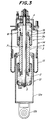
- Fig. 3 shows a modified embodiment of the device shown in Fig. 2, wherein the sliding guide 13 is constructed by a generally used slide bearing or roll bearing and is fixed to each end portion of the restricted passage constituting member 3 through a snap ring 16 so as not to come out from the restricted passage constituting member 3.
- Fig. 4 shows an embodiment in which the sliding guide 13 is fastened to the restricted passage constituting member 3 at a position corresponding to the fixing position of the cylindrical and flexible membrane member 1, 2 to the member 3 through clamping, whereby the stroke quantity of the face plate 4, 5 is made large.
- a support 3b for the sliding guide is jointed to a body portion of the restricted passage constituting member 3 by welding and the sliding guide 3 is attached to the support 3b for the sliding guide through a snap ring 16, while plural through-holes 3c are formed in the support 3b so as to extend in the axial direction of the rigid member 7.
- the sliding guide 13 is attached to an inside of an enlarged portion formed in the end portion of the restricted passage constituting member 3 through the snap ring 16.
- the restricted passage constituting member 3 is constituted by inner and outer double cylindrical members 3d and 3e fixed to each other, wherein the restricted passage 9 is formed by the inner cylindrical member 3d and fastened at its outward flange to the cup-like member 12a, and each of the cylindrical and flexible membrane members 1 and 2 is connected to the respective end portion of the outer cylindrical member 3e.
- the sliding member 13 guides the sliding motion of the rigid member 7 under a low friction force likewise the embodiment of Fig. 1 and simultaneously gives a sufficient rigidity to the device against external force in a direction crossing with the axial line of the rigid member 7 and further can act to effectively prevent the premature breakage of the folded portions 1a, 2a in the cylindrical and flexible membrane members 1, 2 due to the extremely small curvature of radius.
- Fig. 6 is a longitudinal section view of an embodiment of the vibration damping device according to the second aspect of the invention, in which the same parts as in Figs. 1 to 5 are represented by the same numerals.
- Each end portion of the cylindrical and flexible membrane members 1, 2 is liquid-tightly connected to the respective end portion of the restricted passage constituting member 3 being substantially cylindrical as a whole, and the other end portion of each of the members 1, 2 is liquid-tightly connected to each of respective face plates 4, 5 to form a closed chamber 6.
- the face plates 4, 5 are connected to each other through the rigid member 7 inside the closed chamber 6.
- An electrorheological fluid is used as a fluid 8 filled in the closed chamber 6, while electrodes 10 contacting with the electrorheological fluid are arranged on the restricted passage constituting member 3 and hence the peripheral wall of the restricted passage 9 formed in the central portion of the member 3 in the lengthwise direction thereof inside the closed chamber 6.
- the fastening members 11, 12 are attached to the face plate 4 and the restricted passage constituting member 3, respectively, in the same manner as in the aforementioned embodiment.
- such a vibration damping device can effectively absorb high frequency slight vibrations under the deformation of the cylindrical and flexible membrane members 1, 2 and effectively damp large amplitude vibrations under small displacement resistance of the rigid member 7.
- one of the electrodes is connected to earth and a voltage is applied to the remaining electrode 10 connected to a direct current source through a lead wire 17, whereby the viscosity of the electrorheological fluid is increased in accordance with the applied voltage, and consequently the flowing resistance of the electrorheological fluid and hence the increase of the vibration damping force is attained.
- an alternating current source may be used instead of the direct current source. In this case, the increase of the vibration damping force can be attained.
- Figs. 7a to 7e shows various electrode arrangements.
- Figs. 7a and 7b are the same case as in Fig. 6, wherein one of the electrodes is connected to earth and the remaining other electrode is connected to the direct current source through the lead wire 17.
- the electrode arrangement can be simplified.
- the electrode may be constructed by cutting a plate material in the embodiment of Fig. 7b.
- the rigid member 7 is connected to the direct current source through the lead wire 17, while the restricted passage constituting member 3 is connected to earth through the fastening member 12.
- the voltage may be applied to the electrorheological fluid without arranging special electrodes.
- Figs. 7d and 7e two pairs of electrode plates opposing to each other are disposed on the peripheral wall of the restricted passage to constitute the electrodes 10, in which two electrode plates are connected to the direct current source through separate lead wires 17 and the remaining two electrode plates are connected to earth.
- the vibration damping force can be adjusted at plural stages by independently applying the voltage to each pair of the electrode plates without changing the applied voltage.
- This adjusting stages may be increased by arranging three pairs or more of the electrode plates, if necessary.
- the vibration damping force can always be stably developed and may be changed, if necessary.
- the structure of the device is simple and may be miniaturized as a suspension device and also the cost can be reduced.
Applications Claiming Priority (4)
| Application Number | Priority Date | Filing Date | Title |
|---|---|---|---|
| JP21720489 | 1989-08-25 | ||
| JP217204/89 | 1989-08-25 | ||
| JP165682/90 | 1990-06-26 | ||
| JP2165682A JPH03234938A (ja) | 1989-08-25 | 1990-06-26 | 振動減衰装置 |
Publications (2)
| Publication Number | Publication Date |
|---|---|
| EP0414508A1 EP0414508A1 (en) | 1991-02-27 |
| EP0414508B1 true EP0414508B1 (en) | 1996-12-11 |
Family
ID=26490334
Family Applications (1)
| Application Number | Title | Priority Date | Filing Date |
|---|---|---|---|
| EP90309175A Expired - Lifetime EP0414508B1 (en) | 1989-08-25 | 1990-08-21 | Vibration damping device |
Country Status (4)
| Country | Link |
|---|---|
| US (1) | US5366048A (ja) |
| EP (1) | EP0414508B1 (ja) |
| JP (1) | JPH03234938A (ja) |
| DE (1) | DE69029345T2 (ja) |
Cited By (1)
| Publication number | Priority date | Publication date | Assignee | Title |
|---|---|---|---|---|
| CN107143601A (zh) * | 2017-06-01 | 2017-09-08 | 中国科学院长春光学精密机械与物理研究所 | 一种液体阻尼器 |
Families Citing this family (62)
| Publication number | Priority date | Publication date | Assignee | Title |
|---|---|---|---|---|
| DE3922744A1 (de) * | 1989-07-11 | 1991-01-24 | Sigma Laborzentrifugen Gmbh | Schwingungsdaempfer und schwingungsgedaempfte zentrifugenlagerung |
| DE69128585T2 (de) * | 1990-09-25 | 1998-05-20 | Bridgestone Corp | Schwingungsdämpfungsvorrichtung |
| JPH04219536A (ja) * | 1990-09-25 | 1992-08-10 | Bridgestone Corp | 振動減衰装置 |
| DE69128129T2 (de) * | 1990-12-10 | 1998-03-05 | Bridgestone Corp | Einrichtung zur elektroviskosen Dämpfung |
| US5180145A (en) * | 1991-05-30 | 1993-01-19 | Bridgestone Corporation | Vibration damping device |
| US5332070A (en) * | 1993-04-21 | 1994-07-26 | Honeywell Inc. | Three parameter viscous damper and isolator |
| US5449150A (en) * | 1993-11-29 | 1995-09-12 | Bridgestone Corporation | Vibration damping device with an electrode and having rolling lobes of different radii |
| DE4407740C2 (de) * | 1994-03-08 | 1995-12-21 | Daimler Benz Ag | Luftfeder für Kraftfahrzeuge |
| US5992582A (en) * | 1994-04-19 | 1999-11-30 | Lou; Zheng | Electrorheological rotary pure-shear damping devices |
| US5492312A (en) * | 1995-04-17 | 1996-02-20 | Lord Corporation | Multi-degree of freedom magnetorheological devices and system for using same |
| US5590745A (en) * | 1995-06-19 | 1997-01-07 | Bridgestone/Firestone, Inc. | Vibration damping device using ER fluids having multiple electrodes |
| US5588509A (en) * | 1995-10-17 | 1996-12-31 | Bridgestone/Firestone, Inc. | Splined vibration damping device using ER fluids |
| US5899443A (en) * | 1996-10-22 | 1999-05-04 | The United States Of America As Represented By The Secretary Of The Navy | Passive-active vibration isolation |
| DE19647136A1 (de) * | 1996-11-14 | 1998-05-28 | Stop Choc Schwingungstechnik Gmbh & Co Kg | Dämpferelement und Schwingungsdämpfer mit einem solchen |
| US5921357A (en) * | 1997-04-14 | 1999-07-13 | Trw Inc. | Spacecraft deployment mechanism damper |
| US6082508A (en) * | 1997-04-23 | 2000-07-04 | Honeywell International Inc. | Pneumatic damping strut |
| US6129185A (en) * | 1997-12-30 | 2000-10-10 | Honeywell International Inc. | Magnetically destiffened viscous fluid damper |
| JP2000108189A (ja) | 1998-10-09 | 2000-04-18 | Husky Injection Molding Syst Ltd | 振動減衰装置、振動減衰方法、及び油圧射出成形装置 |
| US6237381B1 (en) * | 1998-12-01 | 2001-05-29 | Smedberg Industries, Ltd. | Power press ram force modulation and apparatus for use therewith |
| US6460396B1 (en) | 1998-12-01 | 2002-10-08 | Metalforming Controls Corp. | Power press |
| US6116784A (en) * | 1999-01-07 | 2000-09-12 | Brotz; Gregory R. | Dampenable bearing |
| US6302249B1 (en) * | 1999-03-08 | 2001-10-16 | Lord Corporation | Linear-acting controllable pneumatic actuator and motion control apparatus including a field responsive medium and control method therefor |
| US6318521B1 (en) | 1999-06-16 | 2001-11-20 | Bridgestone/Firestone, Inc. | Externally guided ER damper |
| US6607186B2 (en) | 2000-05-01 | 2003-08-19 | Bret Voelkel | Shock absorber |
| US6279702B1 (en) * | 2001-01-05 | 2001-08-28 | Mando Corporation | Shock absorber using a hydraulic fluid and a magnetorheological fluid |
| US6360856B1 (en) * | 2001-01-05 | 2002-03-26 | Mando Corporation | Double-tube shock absorber using a hydraulic fluid and a magnetorheological fluid |
| US6561500B2 (en) * | 2001-03-07 | 2003-05-13 | The Goodyear Tire & Rubber Company | Hydro-damped air spring |
| US6752250B2 (en) * | 2001-09-27 | 2004-06-22 | Northrop Grumman Corporation | Shock, vibration and acoustic isolation system |
| DE10204956A1 (de) * | 2002-02-06 | 2003-08-14 | Fuchs Petrolub Ag | Dämpfersystem insbesondere für magnetorheologische Flüssigkeiten |
| DE10224442C1 (de) * | 2002-06-01 | 2003-10-09 | Contitech Luftfedersyst Gmbh | Federungseinrichtung |
| DE10224868B3 (de) * | 2002-06-05 | 2004-03-25 | Daimlerchrysler Ag | Kombiniertes Feder-Dämpfersystem mit Luftfederung |
| US20040026836A1 (en) * | 2002-08-07 | 2004-02-12 | Brookes Graham R. | Vehicle suspension system |
| DE10311263B3 (de) * | 2003-03-14 | 2004-07-29 | Audi Ag | Luftfeder mit einer ersten und einer zweiten Arbeitskammer mit unterschiedlichen Durchmessern und Volumina |
| US6983832B2 (en) * | 2003-10-22 | 2006-01-10 | General Motors Corporation | Impact energy absorber and process |
| DE102004012881A1 (de) * | 2004-03-16 | 2005-10-06 | Daimlerchrysler Ag | Gasfedersystem mit zentral geführtem Schlauchrollbalg |
| IL161900A (en) * | 2004-05-09 | 2011-01-31 | Rami Ben Maimon | Vibration reliever for vacuum pump |
| US7284644B2 (en) * | 2005-03-16 | 2007-10-23 | Bfs Diversified Products, Llc | Multiple load path air spring assembly |
| DE102005018132B4 (de) * | 2005-04-20 | 2010-11-04 | Carl Freudenberg Kg | Schlauchrollbalg für pneumatische und/oder hydropneumatische Federungs- bzw. Dämpfungselemente |
| JP2006327296A (ja) * | 2005-05-24 | 2006-12-07 | Kayaba Ind Co Ltd | エアサスペンション装置 |
| JP4611802B2 (ja) * | 2005-05-24 | 2011-01-12 | カヤバ工業株式会社 | エアサスペンション装置 |
| US7591353B2 (en) * | 2005-11-30 | 2009-09-22 | Gm Global Technology Operations, Inc. | Decoupled mono tube damper assembly |
| DE102007003063A1 (de) * | 2007-01-20 | 2008-07-31 | Carl Freudenberg Kg | Verstellbares Luftfeder-Dämpfer-Element |
| US7896142B2 (en) * | 2007-03-15 | 2011-03-01 | Tenneco Automotive Operating Company Inc. | Shock absorber dirt shield |
| EP2310716B1 (en) * | 2008-07-09 | 2018-05-30 | Firestone Industrial Products Company, LLC | Gas spring and gas damper assembly and method |
| DE102008053617A1 (de) * | 2008-10-29 | 2010-05-06 | Audi Ag | Radaufhängung für Kraftfahrzeuge |
| US8347793B2 (en) * | 2009-05-22 | 2013-01-08 | Toppan Photomasks, Inc. | Apparatus for transport of equipment and method for manufacture thereof |
| US8833722B2 (en) * | 2009-05-22 | 2014-09-16 | Toppan Photomasks, Inc. | Apparatus for transport of equipment and method for manufacture thereof |
| US8172194B2 (en) | 2009-05-22 | 2012-05-08 | Toppan Photomasks, Inc. | Apparatus for transport of equipment and method for manufacture thereof |
| DE102009034677B4 (de) * | 2009-07-24 | 2013-10-31 | Trelleborg Automotive Germany Gmbh | Dämpfungseinrichtung |
| JP5414642B2 (ja) * | 2010-09-10 | 2014-02-12 | 三菱電機株式会社 | 振動絶縁装置 |
| US9744824B2 (en) | 2015-03-25 | 2017-08-29 | Hendrickson Usa, L.L.C. | Damping air spring and shock absorber combination for heavy-duty vehicle axle/suspension systems |
| DE102015208064A1 (de) * | 2015-04-30 | 2016-11-03 | Siemens Aktiengesellschaft | Verfahren und Anordnung zum Beeinflussen des Dämpfungsverhaltens eines elektrohydraulischen Dämpfers und Dämpfer |
| CA2985744C (en) | 2015-05-11 | 2019-09-24 | Hendrickson Usa, L.L.C. | Air spring with damping characteristics for heavy-duty vehicles |
| DE102017205475A1 (de) * | 2017-03-31 | 2018-10-04 | Zf Friedrichshafen Ag | Schwingungsdämpfer für ein Kraftfahrzeug |
| EP3645908A4 (en) * | 2017-06-26 | 2021-03-24 | HRL Laboratories, LLC | FLUID AND ELASTOMER VIBRATION ISOLATOR |
| US10457386B2 (en) * | 2017-07-13 | 2019-10-29 | Goodrich Corporation | Hydraulic shimmy damper |
| US10465724B2 (en) * | 2017-12-19 | 2019-11-05 | James J. Lee | Pistonless cylinder used for offshore pile gripper |
| US10145081B1 (en) * | 2017-12-19 | 2018-12-04 | James J. Lee | Pistonless cylinder used for offshore pile gripper |
| CN108278313B (zh) * | 2018-01-30 | 2020-06-26 | 广东松山职业技术学院 | 一种双约束膜式低频空气弹簧 |
| US11193506B2 (en) | 2018-11-15 | 2021-12-07 | Canon Kabushiki Kaisha | Pulsation dampener with gas retention |
| DE102018222084A1 (de) * | 2018-12-18 | 2020-06-18 | Zf Friedrichshafen Ag | Horizontal einsetzbarer Schwingungsdämpfer |
| CN111853136A (zh) * | 2020-07-23 | 2020-10-30 | 杭州根基科技有限公司 | 一种基于电流变液的计算机用辅助调整水平装置 |
Family Cites Families (22)
| Publication number | Priority date | Publication date | Assignee | Title |
|---|---|---|---|---|
| BE537348A (ja) * | ||||
| US1729565A (en) * | 1925-07-22 | 1929-09-24 | Caretta Ettore | Fluid-operating shock absorber |
| US1884477A (en) * | 1929-02-18 | 1932-10-25 | Walter P Albert | Vibration dampener |
| US2606631A (en) * | 1946-05-15 | 1952-08-12 | Gen Motors Corp | Fluid controlled retarding apparatus |
| CH319112A (de) * | 1952-10-02 | 1957-01-31 | Daimler Benz Ag | Einrichtung zur Aufhängung eines Antriebsaggregates in einem Kraftfahrzeug |
| US2919883A (en) * | 1958-12-11 | 1960-01-05 | Bendix Aviat Corp | Liquid damped vibration isolator |
| US3046003A (en) * | 1959-07-16 | 1962-07-24 | Midland Ross Corp | Fluid spring |
| GB1282568A (en) * | 1968-12-11 | 1972-07-19 | Laser Engineering Developments | Improvements in or relating to dampers |
| FR2227461A1 (en) * | 1973-04-24 | 1974-11-22 | Peugeot & Renault | Vehicle engine shock absorber mounting - has two chambers with bellows walls connected through mounting block |
| JPS55112440A (en) * | 1979-02-21 | 1980-08-30 | Toshiba Corp | Damper |
| SU1196558A1 (ru) * | 1983-07-13 | 1985-12-07 | Предприятие П/Я В-8451 | Гидродемпфер |
| DE3436664A1 (de) * | 1983-10-07 | 1985-05-02 | Bridgestone Corp., Tokio/Tokyo | Membran-luftfeder |
| JPS6081529A (ja) * | 1983-10-07 | 1985-05-09 | Bridgestone Corp | ダイアフラム形空気ばね |
| US4572488A (en) * | 1983-12-08 | 1986-02-25 | The United States Of America As Represented By The Secretary Of The Air Force | Low temperature rate controller |
| DE3601712A1 (de) * | 1985-02-01 | 1986-09-11 | Rheinische Armaturen- und Maschinenfabrik Albert Sempell, 4052 Korschenbroich | Einrichtung zur kontrolle unerwuenschter bewegungen und auslenkungen |
| US4861006A (en) * | 1986-09-16 | 1989-08-29 | Bridgestone Corporation | Anti-vibration apparatus |
| JP2693434B2 (ja) * | 1986-12-29 | 1997-12-24 | 株式会社ブリヂストン | サスペンション用減衰力発生装置およびそれの作動制御装置 |
| DE3742340A1 (de) * | 1987-01-19 | 1988-07-28 | Volkswagen Ag | Koerperschallisolierendes lager, insbesondere fuer eine brennkraftmaschine |
| DE3722376A1 (de) * | 1987-07-07 | 1989-01-19 | Bayerische Motoren Werke Ag | Fluidgefuelltes gummilager |
| JPS6448635U (ja) * | 1987-09-19 | 1989-03-27 | ||
| US5000299A (en) * | 1989-02-07 | 1991-03-19 | Tokai Rubber Industries, Ltd. | Shock absorber using electro-viscous fluid |
| US5180145A (en) * | 1991-05-30 | 1993-01-19 | Bridgestone Corporation | Vibration damping device |
-
1990
- 1990-06-26 JP JP2165682A patent/JPH03234938A/ja active Pending
- 1990-08-21 EP EP90309175A patent/EP0414508B1/en not_active Expired - Lifetime
- 1990-08-21 DE DE69029345T patent/DE69029345T2/de not_active Expired - Fee Related
-
1994
- 1994-04-12 US US08/226,365 patent/US5366048A/en not_active Expired - Fee Related
Cited By (2)
| Publication number | Priority date | Publication date | Assignee | Title |
|---|---|---|---|---|
| CN107143601A (zh) * | 2017-06-01 | 2017-09-08 | 中国科学院长春光学精密机械与物理研究所 | 一种液体阻尼器 |
| CN107143601B (zh) * | 2017-06-01 | 2019-03-05 | 中国科学院长春光学精密机械与物理研究所 | 一种液体阻尼器 |
Also Published As
| Publication number | Publication date |
|---|---|
| EP0414508A1 (en) | 1991-02-27 |
| JPH03234938A (ja) | 1991-10-18 |
| DE69029345D1 (de) | 1997-01-23 |
| US5366048A (en) | 1994-11-22 |
| DE69029345T2 (de) | 1997-05-15 |
Similar Documents
| Publication | Publication Date | Title |
|---|---|---|
| EP0414508B1 (en) | Vibration damping device | |
| JP3835845B2 (ja) | Er流体を使用する振動緩衝装置 | |
| EP0658703B1 (en) | Vibration damping device | |
| US5172893A (en) | Hydraulic antivibratory sleeves | |
| US5489009A (en) | Vibration damping device | |
| US5000299A (en) | Shock absorber using electro-viscous fluid | |
| KR100261674B1 (ko) | 진동댐핑장치 | |
| US4790520A (en) | Vibration insulating device with flexible diaphragm between radially outer gas chamber and radially inner liquid chamber | |
| EP0478273B1 (en) | Vibration damping device | |
| JP3989573B2 (ja) | 電気レオロジー流体を使用した振動減衰装置 | |
| US5188346A (en) | Fluid-filled elastic mount having two pressure-receiving chambers communicating with equilibrium chamber through respective orifice passages | |
| GB2215810A (en) | Strut for vehicle suspension | |
| EP0524665A2 (en) | Fluid filled elastomeric damping device | |
| JPH0242227A (ja) | 防振装置 | |
| JPS6288834A (ja) | 防振装置 | |
| US5000428A (en) | Fluid-damped strut | |
| JPH01164831A (ja) | 流体封入式円筒型マウント | |
| JPH02209643A (ja) | 緩衝装置 | |
| EP0409579A2 (en) | Movement controlling strut | |
| JPH11141595A (ja) | 防振装置 | |
| JPH07119779A (ja) | 振動減衰装置 | |
| KR100192339B1 (ko) | 액체봉입식 인슐레이터 | |
| JPH0724673Y2 (ja) | 電気粘性流体封入式筒型マウント装置 | |
| JPH0625731Y2 (ja) | 流体封入式防振ブッシュ | |
| JPH02245538A (ja) | 流体封入式筒型マウント装置 |
Legal Events
| Date | Code | Title | Description |
|---|---|---|---|
| PUAI | Public reference made under article 153(3) epc to a published international application that has entered the european phase |
Free format text: ORIGINAL CODE: 0009012 |
|
| AK | Designated contracting states |
Kind code of ref document: A1 Designated state(s): DE FR GB |
|
| 17P | Request for examination filed |
Effective date: 19910814 |
|
| 17Q | First examination report despatched |
Effective date: 19930614 |
|
| GRAH | Despatch of communication of intention to grant a patent |
Free format text: ORIGINAL CODE: EPIDOS IGRA |
|
| GRAH | Despatch of communication of intention to grant a patent |
Free format text: ORIGINAL CODE: EPIDOS IGRA |
|
| GRAH | Despatch of communication of intention to grant a patent |
Free format text: ORIGINAL CODE: EPIDOS IGRA |
|
| GRAA | (expected) grant |
Free format text: ORIGINAL CODE: 0009210 |
|
| AK | Designated contracting states |
Kind code of ref document: B1 Designated state(s): DE FR GB |
|
| REF | Corresponds to: |
Ref document number: 69029345 Country of ref document: DE Date of ref document: 19970123 |
|
| ET | Fr: translation filed | ||
| PLBE | No opposition filed within time limit |
Free format text: ORIGINAL CODE: 0009261 |
|
| STAA | Information on the status of an ep patent application or granted ep patent |
Free format text: STATUS: NO OPPOSITION FILED WITHIN TIME LIMIT |
|
| 26N | No opposition filed | ||
| REG | Reference to a national code |
Ref country code: GB Ref legal event code: IF02 |
|
| PGFP | Annual fee paid to national office [announced via postgrant information from national office to epo] |
Ref country code: FR Payment date: 20040810 Year of fee payment: 15 |
|
| PGFP | Annual fee paid to national office [announced via postgrant information from national office to epo] |
Ref country code: GB Payment date: 20040818 Year of fee payment: 15 |
|
| PGFP | Annual fee paid to national office [announced via postgrant information from national office to epo] |
Ref country code: DE Payment date: 20040902 Year of fee payment: 15 |
|
| PG25 | Lapsed in a contracting state [announced via postgrant information from national office to epo] |
Ref country code: GB Free format text: LAPSE BECAUSE OF NON-PAYMENT OF DUE FEES Effective date: 20050821 |
|
| PG25 | Lapsed in a contracting state [announced via postgrant information from national office to epo] |
Ref country code: DE Free format text: LAPSE BECAUSE OF NON-PAYMENT OF DUE FEES Effective date: 20060301 |
|
| GBPC | Gb: european patent ceased through non-payment of renewal fee |
Effective date: 20050821 |
|
| PG25 | Lapsed in a contracting state [announced via postgrant information from national office to epo] |
Ref country code: FR Free format text: LAPSE BECAUSE OF NON-PAYMENT OF DUE FEES Effective date: 20060428 |
|
| REG | Reference to a national code |
Ref country code: FR Ref legal event code: ST Effective date: 20060428 |