EP0388866B1 - Antriebsstation an einer Vorrichtung zum Einziehen von Materialbahnen - Google Patents
Antriebsstation an einer Vorrichtung zum Einziehen von Materialbahnen Download PDFInfo
- Publication number
- EP0388866B1 EP0388866B1 EP90105185A EP90105185A EP0388866B1 EP 0388866 B1 EP0388866 B1 EP 0388866B1 EP 90105185 A EP90105185 A EP 90105185A EP 90105185 A EP90105185 A EP 90105185A EP 0388866 B1 EP0388866 B1 EP 0388866B1
- Authority
- EP
- European Patent Office
- Prior art keywords
- transport wheel
- drive station
- drive
- station according
- wheel
- Prior art date
- Legal status (The legal status is an assumption and is not a legal conclusion. Google has not performed a legal analysis and makes no representation as to the accuracy of the status listed.)
- Expired - Lifetime
Links
Images

Classifications
-
- B—PERFORMING OPERATIONS; TRANSPORTING
- B41—PRINTING; LINING MACHINES; TYPEWRITERS; STAMPS
- B41F—PRINTING MACHINES OR PRESSES
- B41F13/00—Common details of rotary presses or machines
- B41F13/02—Conveying or guiding webs through presses or machines
- B41F13/03—Threading webs into printing machines
Definitions
- the invention relates to a drive station on a device for drawing in material webs - preferably a paper web drawing device in web-fed rotary printing presses - according to the features in the preamble of patent claim 1.
- a generic device is known from DE-C 35 05 515.
- a feed element is driven by a transport wheel, which is rigidly mounted above it.
- the distance between the transport wheel and the feed element is chosen so that the former protrudes into the path of the latter to such an extent that the teeth on the outer circumference of both parts can come into non-positive engagement.
- a spring-loaded ball protrudes from below into the path of the pull-in element, which, when the same runs in, actuates a switch for connecting a motor driving the transport wheel with the interposition of a drive gear.
- the ball also has the function of pushing the feed element up and thus ensuring its positive engagement with the teeth of the transport wheel.
- the running-in process at this drive station is also not smooth if one tooth head of the pull-in element and the transport wheel meet.
- the invention has for its object to provide a drive station that enables a highly wear-free and jerk-free transport of a feed element.
- pull-in elements flexible rope-like elements with a circular or polygonal cross-section, rope-like elements which are additionally provided with a helical spiral on the outside or chain-like elements.
- all of the retraction elements are suitable for the drive station according to the invention, which allow a positive engagement of a toothed transport wheel.
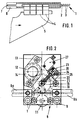
- a pull-in element 1 is formed by a flexible cable 2 with a circular cross section and a helical helix 3 firmly connected thereto on the circumference of the cable, as can be seen in FIG. 1.
- a plurality of fastening elements 4 are arranged, to which a flexible pull element 5 is fastened.
- a paper web, not shown, is connected to this before the drawing-in process.
- the feed element can be moved in a tubular guide 6 with a circular cross section.
- the guide 6 has a slot 7 on one side, through which the fastening members 4 are guided.
- Drive stations 8, one of which is shown in FIG. 2 are arranged at intervals along the printing press.
- Each drive station 8 consists of a base plate 9 to which the guide 6 is fastened and on which all other elements required for the drive are mounted.
- the base plate 9 is in turn attached to a machine side wall of the printing press (not shown).
- the guide 6 instructs at least in the area of a drive station 8 a recess on its upper side, through which an externally toothed transport wheel 10 partially projects into the guide.
- the guide 6 can, however, just as well, as shown in FIG. 2, be interrupted over part of its length.
- both ends 6 a and 6 b of the guide 6 are fastened to the base plate 9 in alignment with their longitudinal axis.
- the feed element 1 is supported from below by a counter pressure roller 11 in the region of the tooth engagement of the transport wheel 10.
- the transport wheel 10 is in engagement with a drive wheel 12 which can be driven by a motor 14 fastened to the base plate 9 by means of a flange 13.
- the motor 14 is preferably designed as a pneumatic motor.
- a bearing 16 receiving the axle ends 15 of the transport wheel 10 is, according to the invention, opposite the longitudinal axis of the feed element 1 against the direction of travel of the same at an acute angle ⁇ against a force F movable.
- the forces acting on the transport wheel 10 can be better seen in the schematic illustration in FIG. 3.
- the force is introduced into the transport wheel 10 by the drive wheel 12 at the common point of contact 17.
- the force is diverted from the transport wheel 10 to the feed element 1 at the common point of contact 18.
- the pitch circle tangents in the points of contact are designated 17 a and 18 a. They are identical to the lines of action of the forces acting on the transport wheel 10 in these points, the driving force F17 and the reaction force F18 of the pull-in element 1 on the transport wheel 10.
- the drive wheel 12 is always arranged to the transport wheel 10 so that the bisector 19 at an acute angle ⁇ / 2 against Running direction of the feed element 1 is inclined.
- there is always a resultant force F res on the transport wheel 10 during operation which pulls the transport wheel 10 into the wedge formed from the pitch circle tangents 17 a and 18 a; and this the stronger, the greater the transmitted driving force F17 or F18.
- the transport wheel 10 is easily movable in the opposite direction, that is, out of the wedge formed by the pitch circle tangents. So it can easily move upwards when the feed element 1 runs in.
- the force F against which the transport wheel 10 is moved is very low. It should only bring about the first tooth engagement of the transport wheel 10 with the feed element 1.
- the force on the bearing 16 of the axles 15 of the transport wheel 10 is exerted by a compression spring 20; with a corresponding mass of the transport wheel 10, the weight of the same will be sufficient to produce the tooth engagement.
- a spring 20 is preferred, the force of which likewise acts on the transport wheel 10 at an acute angle ⁇ counter to the running direction of the feed element 1.
- the angle ⁇ is preferably between 30 ° and 70 °, in a particularly preferred embodiment at 45 °; Also advantageous is an arrangement in which the angle ⁇ corresponds to the angle ⁇ , because the transport wheel 10 is displaced tangentially to the drive wheel 12 and the meshing is best maintained.
- a switching element 21 cooperating with the bearing 16 of the transport wheel 10 is provided, which actuates a switch 22 when the transport wheel is displaced, as indicated schematically in FIG. 3.
- the switching element 21 is designed as a bolt, which is supported with one end on the bearing 16 and the other conically ground end is guided in a bore 23 of a switch housing 24.
- the shaft of the bolt also serves to guide those surrounding it at a short distance Spring 20.
- a blind hole 25 is arranged in the switch housing 24 at right angles to the bore 23.
- a ball 26 is supported in this, which is supported on the conical end of the bolt and is pressed into the bore 25 by the bolt when the transport wheel 10 is displaced. It actuates a pneumatic switch 27 which, directly or indirectly to reduce the switching force required, sets the motor 14 into operation via a pneumatic booster stage.
- the drive wheel 12 and the transport wheel 10 meshing with it are set in rotation.
- the entire drive station 8 acts in the running direction of the feed element 1 as an overrunning clutch or freewheel: As long as the feed element 1 is still from a further back drive station or as soon as it is moved again by a preceding one at a higher speed than the peripheral speed of the transport wheel 10 under consideration, it deviates the angle ⁇ obliquely upwards. However, as soon as the driving force of the drive station under consideration becomes effective after the run-up, the tooth engagement between the transport wheel 10 and the feed element 1 is automatically maintained due to the resulting force F res described above.
- the oblique displacement of the bearing 16 shown in FIGS. 2 and 5 is provided in a slot-like guide 28, in which the ⁇ angle remains unchanged.
- a pivoting of the transport wheel 10b on a circular arc 29 around the axis of the drive wheel 12b is also possible, in which the angle ⁇ varies slightly with the small pivoting distance to be covered.
- the transport wheel 10 b is mounted in a pivot lever 30 b rotatable about the axis of the drive wheel 12 b.
- a spring 20 b acts on the latter, the force of which acts analogously to that of the spring 20 in FIG. 3 in the direction of the wedge formed by the pitch circle tangents.
Landscapes
- Engineering & Computer Science (AREA)
- Mechanical Engineering (AREA)
- Advancing Webs (AREA)
- Replacement Of Web Rolls (AREA)
- Controlling Rewinding, Feeding, Winding, Or Abnormalities Of Webs (AREA)
Applications Claiming Priority (2)
| Application Number | Priority Date | Filing Date | Title |
|---|---|---|---|
| DE3909470A DE3909470C1 (enExample) | 1989-03-22 | 1989-03-22 | |
| DE3909470 | 1989-03-22 |
Publications (3)
| Publication Number | Publication Date |
|---|---|
| EP0388866A2 EP0388866A2 (de) | 1990-09-26 |
| EP0388866A3 EP0388866A3 (de) | 1991-08-21 |
| EP0388866B1 true EP0388866B1 (de) | 1994-02-09 |
Family
ID=6376990
Family Applications (1)
| Application Number | Title | Priority Date | Filing Date |
|---|---|---|---|
| EP90105185A Expired - Lifetime EP0388866B1 (de) | 1989-03-22 | 1990-03-20 | Antriebsstation an einer Vorrichtung zum Einziehen von Materialbahnen |
Country Status (4)
| Country | Link |
|---|---|
| US (1) | US5029742A (enExample) |
| EP (1) | EP0388866B1 (enExample) |
| JP (1) | JPH02282149A (enExample) |
| DE (2) | DE3909470C1 (enExample) |
Families Citing this family (14)
| Publication number | Priority date | Publication date | Assignee | Title |
|---|---|---|---|---|
| FR2663132B1 (fr) * | 1990-06-11 | 1993-05-28 | Kodak Pathe | Dispositif d'interfacage entre un poste debiteur et un poste recepteur de pellicule photographique. |
| JPH0657578B2 (ja) * | 1990-12-13 | 1994-08-03 | 株式会社東京機械製作所 | 紙通し装置 |
| FR2684042B1 (fr) * | 1991-11-26 | 1996-06-07 | Heidelberg Harris Sa | Dispositif d'engagement de bande pour presse a imprimer a bobine. |
| DE4325251C5 (de) * | 1993-07-28 | 2006-07-13 | Man Roland Druckmaschinen Ag | Vorrichtung zum Einziehen von Bedruckstoffbahnen durch einen Trockner |
| US6223962B1 (en) * | 1999-06-17 | 2001-05-01 | Heidelberger Druckmaschinen Aktiengesellschaft | Method and apparatus for attaching a web of material for translation through a rotary printing press system |
| DE10015857A1 (de) * | 2000-03-30 | 2001-10-11 | Heidelberger Druckmasch Ag | Bahneinzugsvorrichtung mit dezentralen Verbindungsstationen |
| EP1138482B1 (de) | 2000-03-30 | 2003-11-12 | Heidelberger Druckmaschinen Aktiengesellschaft | Bahneinzugsvorrichtung mit dezentralen Verbindungsstationen |
| DE10024012B4 (de) * | 2000-05-16 | 2004-10-21 | Koenig & Bauer Ag | Vorrichtung zum Einziehen einer Bahn |
| DE10118868A1 (de) * | 2001-04-18 | 2002-10-31 | Koenig & Bauer Ag | Transportvorrichtung |
| JP4445317B2 (ja) * | 2004-04-16 | 2010-04-07 | 西研グラフィックス株式会社 | 自動紙通し装置用牽引走行体 |
| JP5256234B2 (ja) * | 2010-03-18 | 2013-08-07 | 株式会社Pfu | 角度検出装置および画像読取装置 |
| EP2701918B1 (en) * | 2011-04-28 | 2015-06-03 | Hewlett-Packard Development Company, L.P. | Print media gripper arrangement |
| DE102011084935A1 (de) * | 2011-10-21 | 2013-04-25 | Koenig & Bauer Aktiengesellschaft | Verfahren zum Einziehen zumindest einer Materialbahn in eine Verarbeitungsvorrichtung |
| CN112141781A (zh) * | 2020-09-20 | 2020-12-29 | 李萍萍 | 一种斜面带体中部驱动装置 |
Family Cites Families (10)
| Publication number | Priority date | Publication date | Assignee | Title |
|---|---|---|---|---|
| GB1031238A (en) * | 1964-11-06 | 1966-06-02 | Creed & Co Ltd | Intermittent tape feed |
| DE2402768C2 (de) * | 1974-01-22 | 1978-04-20 | Maschinenfabrik Augsburg-Nuernberg Ag, 8900 Augsburg | Vorrichtung zum Einziehen von Materialbahnen in Rotationsdruckmaschinen |
| DE2657789A1 (de) * | 1976-12-21 | 1978-06-29 | Maschf Augsburg Nuernberg Ag | Einrichtung zum einziehen einer papierbahn in den falzapparat einer rotationsdruckmaschine |
| US4111565A (en) * | 1977-03-28 | 1978-09-05 | Xerox Corporation | Apparatus for sensing when paper utilized in a printer has been depleted |
| US4241247A (en) * | 1978-05-23 | 1980-12-23 | Pitney Bowes Inc. | Controller for rotary collator |
| DE8011068U1 (de) * | 1980-04-23 | 1980-07-17 | M.A.N.-Roland Druckmaschinen Ag, 6050 Offenbach | Einzugsvorrichtung fuer rollen- rotationsdruckmaschinen |
| DE3018740C2 (de) * | 1980-05-16 | 1986-02-06 | M.A.N.- Roland Druckmaschinen AG, 6050 Offenbach | Vorrichtung zum Einziehen von Materialbahnen in Rotationsdruckmaschinen |
| DE3405294C2 (de) * | 1984-02-15 | 1986-03-13 | M.A.N.- Roland Druckmaschinen AG, 6050 Offenbach | Einzugsvorrichtung für Rollen-Rotationsdruckmaschinen |
| DE3505515C2 (de) * | 1985-02-16 | 1986-12-11 | M.A.N.- Roland Druckmaschinen AG, 6050 Offenbach | Antriebsstation für eine Einzugsvorrichtung an einer Rollenrotationsdruckmaschine |
| DE3709413A1 (de) * | 1987-03-21 | 1988-09-29 | Agfa Gevaert Ag | Vorrichtung zum anbringen einer den anfang eines bandfoermigen materials fuehrenden klammer an ein schleppband |
-
1989
- 1989-03-22 DE DE3909470A patent/DE3909470C1/de not_active Expired - Lifetime
-
1990
- 1990-02-28 US US07/486,238 patent/US5029742A/en not_active Expired - Fee Related
- 1990-03-16 JP JP2064490A patent/JPH02282149A/ja active Pending
- 1990-03-20 EP EP90105185A patent/EP0388866B1/de not_active Expired - Lifetime
- 1990-03-20 DE DE90105185T patent/DE59004535D1/de not_active Expired - Fee Related
Also Published As
| Publication number | Publication date |
|---|---|
| EP0388866A3 (de) | 1991-08-21 |
| JPH02282149A (ja) | 1990-11-19 |
| DE3909470C1 (enExample) | 1990-03-22 |
| EP0388866A2 (de) | 1990-09-26 |
| DE59004535D1 (de) | 1994-03-24 |
| US5029742A (en) | 1991-07-09 |
Similar Documents
| Publication | Publication Date | Title |
|---|---|---|
| EP0388866B1 (de) | Antriebsstation an einer Vorrichtung zum Einziehen von Materialbahnen | |
| DE3118710C2 (enExample) | ||
| DE3727147A1 (de) | Nachspannendes bohrfutter | |
| DE1461915B2 (de) | Vorrichtung zur Herstellung von Quaderpackungen | |
| DE3148176C2 (de) | Vorrichtung zum Transportieren von Fördergut | |
| EP0716896A1 (de) | Bohrvorrichtung | |
| EP0151791A2 (de) | Spannfutter, insbesondere Bohrfutter | |
| DE3426251A1 (de) | Umreifungsvorrichtung | |
| DE2907386C2 (de) | Vorrichtung zum Bewegen des Druckkopfes eines anschlaglosen Druckers | |
| DE69616482T2 (de) | Stangenzuführvorrichtung mit schaltbarem Vorschub für Mehrspindeldrehmaschinen | |
| DE2607503C3 (de) | Antrieb für eine Blattabzugsvorrichtung | |
| DE3644657C2 (enExample) | ||
| DE2655098C3 (de) | Belegzuführvorrichtung | |
| EP0902399A1 (de) | Speichervorrichtung für kartenförmige Datenträger | |
| CH665742A5 (de) | Vorrichtung zum aufreihen elektrischer bauelemente zu einem gurt. | |
| DE2619261C3 (de) | Fädelvorrichtung für eine Drahterodiermaschine | |
| EP0029464B1 (de) | Einzugapparat an Umformpressen für langgestrecktes Material in Stangen- oder Drehform | |
| DE4142928C2 (de) | Kunststoff-Spritzgießeinheit mit Verriegelungseinrichtung für Förderschnecke und Plastifizierzylinder | |
| DE3505515C2 (de) | Antriebsstation für eine Einzugsvorrichtung an einer Rollenrotationsdruckmaschine | |
| DE2254238C3 (de) | Vorrichtung für das Aus- und Einkuppeln von Schaftmaschinen- und Schlagwelle von Webmaschinen | |
| DE2921415C2 (de) | Vorrichtung zum Aufziehen von Querrippen auf mehrere ortsfeste nebeneinander angeordnete Rohre | |
| DE2822771C2 (de) | Vorrichtung zum Herstellen von an den Stirnseiten angefasten Dübeln aus runden Holzstäben | |
| DE2754542A1 (de) | Andrueckvorrichtung fuer einen belegdrucker | |
| DE3714893A1 (de) | Geraet zum anlegen eines bandes aus thermoplastischem kunststoff um einen gegenstand | |
| DE2810852B1 (de) | Vorrichtung zum selbsttaetigen OEffnen und Schliessen von Werkstoffstangen-Zufuehrungsrohren an Mehrspindel-Stangendrehautomaten |
Legal Events
| Date | Code | Title | Description |
|---|---|---|---|
| PUAI | Public reference made under article 153(3) epc to a published international application that has entered the european phase |
Free format text: ORIGINAL CODE: 0009012 |
|
| AK | Designated contracting states |
Kind code of ref document: A2 Designated state(s): CH DE FR GB IT LI SE |
|
| PUAL | Search report despatched |
Free format text: ORIGINAL CODE: 0009013 |
|
| AK | Designated contracting states |
Kind code of ref document: A3 Designated state(s): CH DE FR GB IT LI SE |
|
| 17P | Request for examination filed |
Effective date: 19910719 |
|
| RHK1 | Main classification (correction) |
Ipc: B41F 13/02 |
|
| 17Q | First examination report despatched |
Effective date: 19930317 |
|
| ITF | It: translation for a ep patent filed | ||
| GRAA | (expected) grant |
Free format text: ORIGINAL CODE: 0009210 |
|
| AK | Designated contracting states |
Kind code of ref document: B1 Designated state(s): CH DE FR GB IT LI SE |
|
| PGFP | Annual fee paid to national office [announced via postgrant information from national office to epo] |
Ref country code: CH Payment date: 19940211 Year of fee payment: 5 |
|
| PGFP | Annual fee paid to national office [announced via postgrant information from national office to epo] |
Ref country code: GB Payment date: 19940215 Year of fee payment: 5 |
|
| PGFP | Annual fee paid to national office [announced via postgrant information from national office to epo] |
Ref country code: DE Payment date: 19940216 Year of fee payment: 5 |
|
| PGFP | Annual fee paid to national office [announced via postgrant information from national office to epo] |
Ref country code: FR Payment date: 19940218 Year of fee payment: 5 |
|
| PGFP | Annual fee paid to national office [announced via postgrant information from national office to epo] |
Ref country code: SE Payment date: 19940223 Year of fee payment: 5 |
|
| REF | Corresponds to: |
Ref document number: 59004535 Country of ref document: DE Date of ref document: 19940324 |
|
| GBT | Gb: translation of ep patent filed (gb section 77(6)(a)/1977) |
Effective date: 19940513 |
|
| ET | Fr: translation filed | ||
| PLBE | No opposition filed within time limit |
Free format text: ORIGINAL CODE: 0009261 |
|
| STAA | Information on the status of an ep patent application or granted ep patent |
Free format text: STATUS: NO OPPOSITION FILED WITHIN TIME LIMIT |
|
| EAL | Se: european patent in force in sweden |
Ref document number: 90105185.4 |
|
| 26N | No opposition filed | ||
| PG25 | Lapsed in a contracting state [announced via postgrant information from national office to epo] |
Ref country code: GB Effective date: 19950320 |
|
| PG25 | Lapsed in a contracting state [announced via postgrant information from national office to epo] |
Ref country code: SE Effective date: 19950321 |
|
| PG25 | Lapsed in a contracting state [announced via postgrant information from national office to epo] |
Ref country code: LI Effective date: 19950331 Ref country code: CH Effective date: 19950331 |
|
| GBPC | Gb: european patent ceased through non-payment of renewal fee |
Effective date: 19950320 |
|
| PG25 | Lapsed in a contracting state [announced via postgrant information from national office to epo] |
Ref country code: FR Free format text: LAPSE BECAUSE OF NON-PAYMENT OF DUE FEES Effective date: 19951130 |
|
| REG | Reference to a national code |
Ref country code: CH Ref legal event code: PL |
|
| PG25 | Lapsed in a contracting state [announced via postgrant information from national office to epo] |
Ref country code: DE Effective date: 19951201 |
|
| EUG | Se: european patent has lapsed |
Ref document number: 90105185.4 |
|
| REG | Reference to a national code |
Ref country code: FR Ref legal event code: ST |
|
| PG25 | Lapsed in a contracting state [announced via postgrant information from national office to epo] |
Ref country code: IT Free format text: LAPSE BECAUSE OF NON-PAYMENT OF DUE FEES;WARNING: LAPSES OF ITALIAN PATENTS WITH EFFECTIVE DATE BEFORE 2007 MAY HAVE OCCURRED AT ANY TIME BEFORE 2007. THE CORRECT EFFECTIVE DATE MAY BE DIFFERENT FROM THE ONE RECORDED. Effective date: 20050320 |