EP0388866B1 - Driving station for a threading device in a web-fed rotary printing press - Google Patents
Driving station for a threading device in a web-fed rotary printing press Download PDFInfo
- Publication number
- EP0388866B1 EP0388866B1 EP90105185A EP90105185A EP0388866B1 EP 0388866 B1 EP0388866 B1 EP 0388866B1 EP 90105185 A EP90105185 A EP 90105185A EP 90105185 A EP90105185 A EP 90105185A EP 0388866 B1 EP0388866 B1 EP 0388866B1
- Authority
- EP
- European Patent Office
- Prior art keywords
- transport wheel
- drive station
- drive
- station according
- wheel
- Prior art date
- Legal status (The legal status is an assumption and is not a legal conclusion. Google has not performed a legal analysis and makes no representation as to the accuracy of the status listed.)
- Expired - Lifetime
Links
Images

Classifications
-
- B—PERFORMING OPERATIONS; TRANSPORTING
- B41—PRINTING; LINING MACHINES; TYPEWRITERS; STAMPS
- B41F—PRINTING MACHINES OR PRESSES
- B41F13/00—Common details of rotary presses or machines
- B41F13/02—Conveying or guiding webs through presses or machines
- B41F13/03—Threading webs into printing machines
Landscapes
- Engineering & Computer Science (AREA)
- Mechanical Engineering (AREA)
- Advancing Webs (AREA)
- Controlling Rewinding, Feeding, Winding, Or Abnormalities Of Webs (AREA)
- Replacement Of Web Rolls (AREA)
Description
Die Erfindung betrifft eine Antriebsstation an einer Vorrichtung zum Einziehen von Materialbahnen - vorzugsweise einer Papierbahn-Einziehvorrichtung an Rollenrotationsdruckmaschinen - gemäß den Merkmalen im Oberbegriff des Patentanspruchs 1.The invention relates to a drive station on a device for drawing in material webs - preferably a paper web drawing device in web-fed rotary printing presses - according to the features in the preamble of
Eine gattungsgemäße Vorrichtung ist aus der DE-C 35 05 515 bekannt. Bei dieser wird ein Einzugselement von einem Transportrad angetrieben, das oberhalb desselben starr gelagert ist. Der Abstand des Transportrades zum Einzugselement ist dabei so gewählt, daß ersteres in den Laufweg des letzteren soweit hineinragt, daß die Verzahnungen am Außenumfang beider Teile in kraftschlüssigen Eingriff geraten können. Von unten her ragt eine federnd gelagerte Kugel in den Laufweg des Einzugselementes, die beim Einlaufen desselben einen Schalter für die Zuschaltung eines das Transportrad unter Zwischenschaltung eines Antriebszahnrades antreibenden Motors betätigt. Die Kugel hat außerdem die Funktion, das Einzugselement nach oben zu drücken und somit dessen formschlüssigen Eingriff mit den Zähnen des Transportrades sicherzustellen.A generic device is known from DE-C 35 05 515. In this case, a feed element is driven by a transport wheel, which is rigidly mounted above it. The distance between the transport wheel and the feed element is chosen so that the former protrudes into the path of the latter to such an extent that the teeth on the outer circumference of both parts can come into non-positive engagement. A spring-loaded ball protrudes from below into the path of the pull-in element, which, when the same runs in, actuates a switch for connecting a motor driving the transport wheel with the interposition of a drive gear. The ball also has the function of pushing the feed element up and thus ensuring its positive engagement with the teeth of the transport wheel.
Abgesehen von der Abnutzung der Kugel und der Verzahnung am Einzugselement durch Gleitreibung gestaltet sich auch der Einlaufvorgang bei dieser Antriebsstation nicht ruckfrei, wenn je ein Zahnkopf des Einzugselements und des Transportrades aufeinandertreffen.Apart from the wear of the ball and the teeth on the pull-in element due to sliding friction, the running-in process at this drive station is also not smooth if one tooth head of the pull-in element and the transport wheel meet.
Der Erfindung liegt die Aufgabe zugrunde, eine Antriebssstation zu schaffen, die einen in höchstem Maße verschleiß- und ruckfreien Transport eines Einzugselements ermöglicht.The invention has for its object to provide a drive station that enables a highly wear-free and jerk-free transport of a feed element.
Diese Aufgabe wird durch die Merkmale im kennzeichnenden Teil des Patentanspruchs 1 gelöst.This object is achieved by the features in the characterizing part of
Durch die Anordnung der Berührpunkte des Transportrades an der Krafteinleitungsstelle mit dem Antriebsrad und an der Kraftausleitungsstelle mit dem Einzugselement derart, daß die Winkelhalbierende des Schnittwinkels β der Wälzkreistangenten in diesen Berührungspunkten unter einem spitzen Winkel β/2 gegen die Laufrichtung des Einzugselements geneigt ist, üben die vom Antriebsrad wirkenden Kräfte eine resultierende Kraft in Richtung der Winkelhalbierenden aus, die das Transportrad im Betrieb selbsttätig in den von den Wälzkreistangenten gebildeten Keilspalt hineinzieht. Dies geschieht um so stärker, je größer die übertragene Kraft ist. Beim Einlaufen des Einzugselements in die Antriebsstation ist das Transportrad dagegen leicht vom Einzugslement in der entgegengesetzten Richtung aus dem Keilspalt heraus bewegbar. Dadurch wird mit einfachen Mitteln eine Antriebsstation geschaffen, die ein selbsttätiges ruckfreies Eingreifen des Einzugselements mit dem Transportrad ohne "Zahnkopfreiten" gewährleistet.By arranging the contact points of the transport wheel at the force introduction point with the drive wheel and at the force discharge point with the pull-in element in such a way that the bisector of the intersection angle β of the pitch circle tangents in these contact points is inclined at an acute angle β / 2 against the running direction of the pull-in element Forces acting from the drive wheel produce a resulting force in the direction of the bisector, which during operation automatically pulls the transport wheel into the wedge gap formed by the pitch circle tangents. The greater the transmitted power, the stronger this happens. When the pull-in element enters the drive station, on the other hand, the transport wheel can be easily moved out of the wedge gap by the pull-in element in the opposite direction. In this way, a drive station is created with simple means, which ensures an automatic, jerk-free engagement of the feed element with the transport wheel without "tooth tip riding".
Vorteilhafte Ausgestaltungen der Erfindung sind den Unteransprüchen zu entnehmen.Advantageous embodiments of the invention can be found in the subclaims.
Nachfolgend sind mehrere Ausführungsbeispiele der Erfindung anhand der Zeichnungen erklärt. Es zeigt:
- Fig. 1
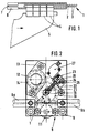
- einen Teil eines Einzugselements mit einer Halterung für eine Papierbahn,
- Fig. 2
- eine Vorderansicht auf eine Antriebsstation mit einem verschiebbaren Transportrad,
- Fig. 3
- eine schematische Darstellung der am Antrieb eines Einzugselements beteiligten Glieder,
- Fig. 4
- eine schematische Darstellung eines verschwenkbaren Transportrades und
- Fig. 5
- eine schematische Darstellung mit einem verschiebbaren Transportrad.
- Fig. 1
- part of a feed element with a holder for a paper web,
- Fig. 2
- a front view of a drive station with a slidable transport wheel,
- Fig. 3
- 1 shows a schematic representation of the links involved in driving a feed element,
- Fig. 4
- a schematic representation of a pivotable transport wheel and
- Fig. 5
- a schematic representation with a slidable transport wheel.
Aus der DE-PS 30 18 740 (Bild 1) ist prinzipiell bekannt, wie Antriebsstationen einer Vorrichtung zum Einziehen von Materialbahnen in bestimmten Abständen längs einer Druckmaschine angeordnet sind. Die folgende Beschreibung beschränkt sich dementsprechend auf die zu einer Antriebsstation gehörenden Teile, das Einzugselement und dessen Führung.From DE-PS 30 18 740 (Figure 1) it is known in principle how drive stations of a device for pulling material webs are arranged at certain intervals along a printing press. The following description is accordingly restricted to the parts belonging to a drive station, the feed element and its guidance.
Als Einzugselemente sind bekannt: flexible seilartige Elemente mit kreisförmigem oder polygonalem Querschnitt, seilartige Elemente, die außen zusätzlich mit einer schraubenlinienförmigen Wendel versehen sind oder kettenartige Elemente. Für die erfindungsgemäße Antriebsstation eignen sich prinzipiell alle Einzugselemente, die einen formschlüssigen Eingriff eines gezahnten Transportrades ermöglichen.The following are known as pull-in elements: flexible rope-like elements with a circular or polygonal cross-section, rope-like elements which are additionally provided with a helical spiral on the outside or chain-like elements. In principle, all of the retraction elements are suitable for the drive station according to the invention, which allow a positive engagement of a toothed transport wheel.
Im beschriebenen Ausführungsbeispiel wird ein Einzugselement 1 von einem flexiblen Seil 2 mit kreisförmigem Querschnitt und einer fest damit verbundenen schraubenlinienförmigen Wendel 3 am Umfang des Seiles gebildet, wie Fig. 1 zu entnehmen ist. Am hinteren Ende des Einzugselements 1 sind mehrere Befestigungsglieder 4 angeordnet, an denen ein flexibles Zugelement 5 befestigt ist. Mit diesem wird eine nicht dargestellte Papierbahn vor dem Einziehvorgang verbunden. Das Einzugselement ist in einer rohrartigen Führung 6 mit kreisförmigem Querschnitt bewegbar. Die Führung 6 weist auf einer Seite durchgehend einen Schlitz 7 auf, durch den die Befestigungsglieder 4 hindurchgeführt sind. Längs der Druckmaschine sind in Abständen Antriebsstationen 8 angeordnet, von denen eine in Fig. 2 dargestellt ist. Der größte Abstand zweier benachbarter, durch Führungen 6 verbundener Antriebsstationen ist kleiner als die Länge des Einzugselements 1, so daß dieses beim Transport stets mit wenigstens einer Antriebsstation 8 in Verbindung steht. Jede Antriebsstation 8 besteht aus einer Grundplatte 9, an der die Führung 6 befestigt ist und an der alle weiteren für den Antrieb erforderlichen Elemente gelagert sind. Die Grundplatte 9 ist ihrerseits an einer Maschinenseitenwand der Druckmaschine (nicht dargestellt) befestigt. Die Führung 6 weist im Bereich einer Antriebsstation 8 wenigstens an ihrer Oberseite eine Ausnehmung auf, durch die ein außen verzahntes Transportrad 10 teilweise in die Führung hineinragt. Die Führung 6 kann aber ebensogut, wie in Fig. 2 dargestellt, auf einem Teil ihrer Länge unterbrochen sein. In diesem Fall sind beide Enden 6 a und 6 b der Führung 6 bezüglich ihrer Längsachse fluchtend an der Grundplatte 9 befestigt. Bei unterbrochener Führung 6 wird das Einzugselement 1 im Bereich des Zahneingriffs des Transportrades 10 von unten her durch eine Gegendruckrolle 11 gestützt. Das Transportrad 10 steht mit einem Antriebsrad 12 im Eingriff, das von einem mittels eines Flansches 13 an der Grundplatte 9 befestigten Motor 14 antreibbar ist. Der Motor 14 ist vorzugsweise als Pneumatikmotor ausgeführt. Während das Antriebsrad 12 und die Führung 6 mit der Gegendruckrolle 11 starr an der Grundplatte 9 gelagert sind, ist eine die Achsenden 15 des Transportrades 10 aufnehmende Lagerung 16 erfindungsgemäß gegenüber der Längsachse des Einzugselements 1 entgegen der Laufrichtung desselben unter einem spitzen Winkel α gegen eine Kraft F bewegbar.In the exemplary embodiment described, a pull-in
Die auf das Transportrad 10 einwirkenden Kräfte sind in der schematischen Darstellung in Fig. 3 besser erkennbar. Die Krafteinleitung in das Transportrad 10 erfolgt durch das Antriebsrad 12 im gemeinsamen Berührungspunkt 17. Die Kraftausleitung aus dem Transportrad 10 an das Einzugselement 1 erfolgt im gemeinsamen Berührungspunkt 18. Die Wälzkreistangenten in den Berührungspunkten sind mit 17 a und 18 a bezeichnet. Sie sind identisch mit den Wirkungslinien der in diesen Punkten auf das Transportrad 10 wirkenden Kräfte, der Antriebskraft F₁₇ und der Reaktionskraft F₁₈ des Einzugselements 1 auf das Transportrad 10. Bei Vernachlässigung der Reibung in der Lagerung 16 des Transportrades 10 sind die beiden Kräfte F₁₇ und F₁₈ gleich groß und bilden eine resultierende Kraft Fres, deren Wirkungslinie mit der Winkelhalbierenden 19 des Winkels β zusammenfällt, den die Walzkreistangenten 17 a und 18 a einschließen.The forces acting on the
Das Antriebsrad 12 ist zum Transportrad 10 stets so angeordnet, daß die Winkelhalbierenden 19 unter einem spitzen Winkel β/2 entgegen der Laufrichtung des Einzugselementes 1 geneigt ist. Dadurch ergibt sich im Betrieb stets eine resultierende Kraft Fres auf das Transportrad 10, die das Transportrad 10 in den aus den Wälzkreistangenten 17 a und 18 a gebildeten Keil hineinzieht; und dies um so stärker, je größer die übertragene Antriebskraft F₁₇ bzw. F₁₈ ist. In umgekehrter Richtung, also aus dem durch die Wälzkreistangenten gebildeten Keil heraus, ist das Transportrad 10 dagegen leicht bewegbar. So kann es beim Einlaufen des Einzugselementes 1 leicht nach oben ausweichen. Die Kraft F, gegen die das Transportrad 10 dabei bewegt wird, ist sehr gering. Sie soll nur den ersten Zahneingriff des Transportrades 10 mit dem Einzugselement 1 bewirken. In Fig. 2 und 3 wird die Kraft auf die Lagerung 16 der Achsen 15 des Transportrades 10 durch eine Druckfeder 20 ausgeübt; bei entsprechender Masse des Transportrades 10 wird die Gewichtskaft desselben ausreichen, um den Zahneingriff herzustellen. Bevorzugt ist jedoch die Verwendung einer Feder 20, deren Kraft ebenfalls unter einem spitzen Winkel α entgegen der Laufrichtung des Einzugselementes 1 auf das Transportrad 10 wirkt. Der Winkel α liegt vorzugsweise zwischen 30° und 70°, in einer besonders bevorzugten Ausführungsform bei 45°; vorteilhaft ist ferner eine Anordnung bei der der Winkel α dem Winkel β entspricht, weil dabei das Transportrad 10 tangential zum Antriebsrad 12 verschoben wird und dabei der Zahneingriff am besten aufrechterhalten wird.The
Vorteilhafterweise wird die Ausweichbewegung des Transportrades 10, die von einem in die Antriebsstation 8 einlaufenden Einzugselement ausgelöst wird, gleichzeitig zur Auslösung eines Schaltvorganges benutzt, durch den der Motor 14 in Betrieb gesetzt wird. Hierzu ist ein mit der Lagerung 16 des Transportrades 10 zusammenwirkendes Schaltelement 21 vorgesehen, das bei Verlagerung des Transportrades einen Schalter 22 betätigt, wie in Fig. 3 schematisch angedeutet ist. In Fig. 2 ist das Schaltelement 21 als Bolzen ausgebildet, der sich mit einem Ende auf der Lagerung 16 abstützt und dessen anderes konisch angeschliffenes Ende in einer Bohrung 23 eines Schaltgehäuses 24 geführt ist. Der Schaft des Bolzens dient gleichzeitig zur Führung der ihn mit geringem Abstand umgebenden Feder 20. Im rechten Winkel zur Bohrung 23 ist im Schaltgehäuse 24 eine Sacklochbohrung 25 angeordnet. In dieser ist eine Kugel 26 gelagert, die sich am konischen Ende des Bolzens abstützt und bei Verlagerung des Transportrades 10 vom Bolzen in die Bohrung 25 gedrückt wird. Dabei betätigt sie einen pneumatischen Schalter 27, der unmittelbar oder zur Reduzierung der erforderlichen Schaltkraft mittelbar über eine pneumatische Verstärkerstufe den Motor 14 in Tätigkeit setzt.Advantageously, the evasive movement of the
Beim Anlauf des Motors 14 werden das Antriebsrad 12 und das mit diesem im Eingriff stehende Transportrad 10 in Drehung versetzt. Die gesamte Antriebsstation 8 wirkt in Laufrichtung des Einzugselements 1 als Überholkupplung oder Freilauf: Solange das Einzugselement 1 von einer weiter zurückliegenden Antriebsstation noch oder sobald es von einer vorausliegenden schon wieder mit einer größeren Geschwindigkeit als der Umfangsgeschwindigkeit des betrachteten Transportrades 10 bewegt wird, weicht dieses unter dem Winkel α schräg nach oben aus. Sobald jedoch die Antriebskraft der betrachteten Antriebsstation nach dem Hochlaufen wirksam wird, wird der Zahneingriff zwischen Transportrad 10 und Einzugselement 1 aufgrund der weiter oben beschriebenen resultierenden Kraft Fres selbsttätig aufrechterhalten.When the
Als Varianten für eine Ausweichbewegung des Transportrades 10 ist zum einen die in den Fig. 2 und 5 dargestellte schräge Verschiebung der Lagerung 16 in einer langlochartigen Führung 28 vorgesehen, bei der der α Winkel unverändert bleibt. Zum anderen ist auch eine Veschwenkung des Transportrades 10 b auf einem Kreisbogen 29 um die Achse des Antriebsrades 12 b möglich, bei der der Winkel α bei dem geringen zurückzulegenden Schwenkweg leicht variiert. Bei dieser in Fig. 4 dargestellten Variante ist das Transportrad 10 b in einem um die Achse des Antriebsrades 12 b drehbaren Schwenkhebel 30 gelagert. An diesem greift des weiteren eine Feder 20 b an, deren Kraft analog zu der der Feder 20 in Fig. 3 in Richtung des von den Wälzkreistangenten gebildeten Keiles wirkt.As an alternative for an evasive movement of the
Claims (9)
- Drive station in a device for threading material webs, preferably a paper-web-threading device in web-fed rotary printing machines, having a threading element provided with means for the positive introduction of force, on which threading element the material web can be fixed, the threading element being movable in a tubular, slotted guideway by the positive engagement of a transport wheel driven by a motor with the intermediate connection of a drive wheel, and a switch for activating the motor being actuatable by means of the end of the element feeding into the drive station, characterised in that- the rolling circle tangent (17a) at the contact point (17) of the drive wheel (12) and the transport wheel (10, 10b) forms an angle β with the rolling circle tangent (18a) at the contact point (18) of the transport wheel (10) and the threading element (1), the bisector (19) of which angle β is inclined at an acute angle (β/2) counter to the running direction of the threading element (1) and- in that a bearing (16) receiving the axle ends (15) of the transport wheel (10, 10b) can be moved at an acute angle α with respect to the longitudinal axis of the threading element (1) counter to the running direction of the same against a force F.
- Drive station according to claim 1, characterised in that the switch (27) for activating the motor (14) can be actuated by means of a displacement of the transport wheel (10, 10b) caused by the in-running threading element (1) via an actuating element (21) connected to the bearing (16).
- Drive station according to one of the preceding claims, characterised in that the force F is produced by a spring (20, 20 b).
- Drive station according to one of the preceding claims, characterised in that the transport wheel (10) is movable along a straight line.
- Drive station according to one of the preceding claims, characterised in that the acute angle α is between 30° and 70°.
- Drive station according to one of the preceding claims, characterised in that the acute angle α is 45°.
- Drive station according to one of the preceding claims, characterised in that the angle β corresponds to the angle α.
- Drive station according to one of claims 1 to 3, characterised in that the mounting (16b) of the transport wheel (10b) can be pivoted on an arc (29) about the axis of the drive wheel (12b).
- Drive station according to one of the preceding claims, characterised in that to reduce the switch force a pneumatic amplification arrangement is mounted in front of the switch for activating the motor (14).
Applications Claiming Priority (2)
| Application Number | Priority Date | Filing Date | Title |
|---|---|---|---|
| DE3909470A DE3909470C1 (en) | 1989-03-22 | 1989-03-22 | |
| DE3909470 | 1989-03-22 |
Publications (3)
| Publication Number | Publication Date |
|---|---|
| EP0388866A2 EP0388866A2 (en) | 1990-09-26 |
| EP0388866A3 EP0388866A3 (en) | 1991-08-21 |
| EP0388866B1 true EP0388866B1 (en) | 1994-02-09 |
Family
ID=6376990
Family Applications (1)
| Application Number | Title | Priority Date | Filing Date |
|---|---|---|---|
| EP90105185A Expired - Lifetime EP0388866B1 (en) | 1989-03-22 | 1990-03-20 | Driving station for a threading device in a web-fed rotary printing press |
Country Status (4)
| Country | Link |
|---|---|
| US (1) | US5029742A (en) |
| EP (1) | EP0388866B1 (en) |
| JP (1) | JPH02282149A (en) |
| DE (2) | DE3909470C1 (en) |
Families Citing this family (14)
| Publication number | Priority date | Publication date | Assignee | Title |
|---|---|---|---|---|
| FR2663132B1 (en) * | 1990-06-11 | 1993-05-28 | Kodak Pathe | INTERFACING DEVICE BETWEEN A DEBITTING STATION AND A PHOTOGRAPHIC FILM RECEIVING STATION. |
| JPH0657578B2 (en) * | 1990-12-13 | 1994-08-03 | 株式会社東京機械製作所 | Paper threading device |
| FR2684042B1 (en) * | 1991-11-26 | 1996-06-07 | Heidelberg Harris Sa | TAPE ENGAGING DEVICE FOR A COIL PRINTING PRESS. |
| DE4325251C5 (en) * | 1993-07-28 | 2006-07-13 | Man Roland Druckmaschinen Ag | Device for drawing in substrate webs through a dryer |
| US6223962B1 (en) * | 1999-06-17 | 2001-05-01 | Heidelberger Druckmaschinen Aktiengesellschaft | Method and apparatus for attaching a web of material for translation through a rotary printing press system |
| EP1138482B1 (en) | 2000-03-30 | 2003-11-12 | Heidelberger Druckmaschinen Aktiengesellschaft | Web infeed device with decentralised link-up stations |
| DE10015857A1 (en) * | 2000-03-30 | 2001-10-11 | Heidelberger Druckmasch Ag | Device for drawing a material web into a rotary printing machine has hanging stations for web associated with components of machine along path of threading material web through machine |
| DE10024012B4 (en) * | 2000-05-16 | 2004-10-21 | Koenig & Bauer Ag | Device for pulling a web |
| DE10118868A1 (en) * | 2001-04-18 | 2002-10-31 | Koenig & Bauer Ag | transport device |
| JP4445317B2 (en) * | 2004-04-16 | 2010-04-07 | 西研グラフィックス株式会社 | Towing traveling body for automatic paper threading device |
| JP5256234B2 (en) * | 2010-03-18 | 2013-08-07 | 株式会社Pfu | Angle detection device and image reading device |
| US20140037357A1 (en) * | 2011-04-28 | 2014-02-06 | Hewlett-Packard Development Company, L.P. | Print media gripper arrangement |
| DE102011084935A1 (en) * | 2011-10-21 | 2013-04-25 | Koenig & Bauer Aktiengesellschaft | Method for drawing at least one material web into a processing device |
| CN112141781A (en) * | 2020-09-20 | 2020-12-29 | 李萍萍 | Inclined plane area body middle part drive arrangement |
Family Cites Families (10)
| Publication number | Priority date | Publication date | Assignee | Title |
|---|---|---|---|---|
| GB1031238A (en) * | 1964-11-06 | 1966-06-02 | Creed & Co Ltd | Intermittent tape feed |
| DE2402768C2 (en) * | 1974-01-22 | 1978-04-20 | Maschinenfabrik Augsburg-Nuernberg Ag, 8900 Augsburg | Device for drawing in webs of material in rotary printing machines |
| DE2657789A1 (en) * | 1976-12-21 | 1978-06-29 | Maschf Augsburg Nuernberg Ag | DEVICE FOR PULLING A PAPER TRAIL INTO THE FOLDER OF A ROTARY PRINTING MACHINE |
| US4111565A (en) * | 1977-03-28 | 1978-09-05 | Xerox Corporation | Apparatus for sensing when paper utilized in a printer has been depleted |
| US4241247A (en) * | 1978-05-23 | 1980-12-23 | Pitney Bowes Inc. | Controller for rotary collator |
| DE8011068U1 (en) * | 1980-04-23 | 1980-07-17 | M.A.N.-Roland Druckmaschinen Ag, 6050 Offenbach | FEED DEVICE FOR ROLL ROTARY PRINTING MACHINES |
| DE3018740C2 (en) * | 1980-05-16 | 1986-02-06 | M.A.N.- Roland Druckmaschinen AG, 6050 Offenbach | Device for drawing in webs of material in rotary printing machines |
| DE3405294C2 (en) * | 1984-02-15 | 1986-03-13 | M.A.N.- Roland Druckmaschinen AG, 6050 Offenbach | Feeding device for web-fed rotary printing machines |
| DE3505515C2 (en) * | 1985-02-16 | 1986-12-11 | M.A.N.- Roland Druckmaschinen AG, 6050 Offenbach | Drive station for a feed device on a web-fed rotary printing press |
| DE3709413A1 (en) * | 1987-03-21 | 1988-09-29 | Agfa Gevaert Ag | DEVICE FOR ATTACHING A CLAMP LEADING THE BEGINNING OF A BAND-SHAPED MATERIAL TO A TOWING TAPE |
-
1989
- 1989-03-22 DE DE3909470A patent/DE3909470C1/de not_active Expired - Lifetime
-
1990
- 1990-02-28 US US07/486,238 patent/US5029742A/en not_active Expired - Fee Related
- 1990-03-16 JP JP2064490A patent/JPH02282149A/en active Pending
- 1990-03-20 EP EP90105185A patent/EP0388866B1/en not_active Expired - Lifetime
- 1990-03-20 DE DE90105185T patent/DE59004535D1/en not_active Expired - Fee Related
Also Published As
| Publication number | Publication date |
|---|---|
| DE59004535D1 (en) | 1994-03-24 |
| EP0388866A2 (en) | 1990-09-26 |
| DE3909470C1 (en) | 1990-03-22 |
| US5029742A (en) | 1991-07-09 |
| EP0388866A3 (en) | 1991-08-21 |
| JPH02282149A (en) | 1990-11-19 |
Similar Documents
| Publication | Publication Date | Title |
|---|---|---|
| EP0388866B1 (en) | Driving station for a threading device in a web-fed rotary printing press | |
| DE3118710C2 (en) | ||
| DE3727147A1 (en) | TENSIONING DRILL CHUCK | |
| DE1461915B2 (en) | Device for the production of square packs | |
| DE3148176C2 (en) | Device for transporting goods to be conveyed | |
| EP0151791A2 (en) | Chuc in particular drill chuck | |
| DE1043576B (en) | Device for curling threads, in particular artificial threads or bundles of threads | |
| DE3426251A1 (en) | STRAPPING DEVICE | |
| EP0716896A1 (en) | Drilling device | |
| DE2907386C2 (en) | Device for moving the print head of a non-impact printer | |
| DE2655098C3 (en) | Document feeder | |
| DE2607503C3 (en) | Drive for a sheet removal device | |
| DE3644657C2 (en) | ||
| EP0902399A1 (en) | Storage arrangement for card-shaped data carriers | |
| CH665742A5 (en) | DEVICE FOR LINING ELECTRICAL COMPONENTS TO A BELT. | |
| DE2619261C3 (en) | Threading device for a wire EDM | |
| EP0029464B1 (en) | Feeding device, for transformation presses for elongate material such as bars or wires | |
| EP0638376B1 (en) | Device for controllable greasing of work pieces with greasing rolls driven by a motor with a belt drive and a primary shaft | |
| DE4142928C2 (en) | Plastic injection molding unit with locking device for screw conveyor and plasticizing cylinder | |
| DE3505515C2 (en) | Drive station for a feed device on a web-fed rotary printing press | |
| DE2921415C2 (en) | Device for pulling transverse ribs onto several stationary pipes arranged next to one another | |
| DE2822771C2 (en) | Device for producing dowels with chamfered end faces from round wooden rods | |
| DE2754542A1 (en) | Document printer pressure unit - has catches rotatably attached to two spindles and is attached on parts extending from two stops | |
| DE3714893A1 (en) | DEVICE FOR PUTTING A STRAP OF THERMOPLASTIC PLASTIC ON AN OBJECT | |
| DE2810852B1 (en) | Device for the automatic opening and closing of bar feed tubes on multi-spindle automatic bar lathes |
Legal Events
| Date | Code | Title | Description |
|---|---|---|---|
| PUAI | Public reference made under article 153(3) epc to a published international application that has entered the european phase |
Free format text: ORIGINAL CODE: 0009012 |
|
| AK | Designated contracting states |
Kind code of ref document: A2 Designated state(s): CH DE FR GB IT LI SE |
|
| PUAL | Search report despatched |
Free format text: ORIGINAL CODE: 0009013 |
|
| AK | Designated contracting states |
Kind code of ref document: A3 Designated state(s): CH DE FR GB IT LI SE |
|
| 17P | Request for examination filed |
Effective date: 19910719 |
|
| RHK1 | Main classification (correction) |
Ipc: B41F 13/02 |
|
| 17Q | First examination report despatched |
Effective date: 19930317 |
|
| ITF | It: translation for a ep patent filed |
Owner name: BARZANO' E ZANARDO ROMA S.P.A. |
|
| GRAA | (expected) grant |
Free format text: ORIGINAL CODE: 0009210 |
|
| AK | Designated contracting states |
Kind code of ref document: B1 Designated state(s): CH DE FR GB IT LI SE |
|
| PGFP | Annual fee paid to national office [announced via postgrant information from national office to epo] |
Ref country code: CH Payment date: 19940211 Year of fee payment: 5 |
|
| PGFP | Annual fee paid to national office [announced via postgrant information from national office to epo] |
Ref country code: GB Payment date: 19940215 Year of fee payment: 5 |
|
| PGFP | Annual fee paid to national office [announced via postgrant information from national office to epo] |
Ref country code: DE Payment date: 19940216 Year of fee payment: 5 |
|
| PGFP | Annual fee paid to national office [announced via postgrant information from national office to epo] |
Ref country code: FR Payment date: 19940218 Year of fee payment: 5 |
|
| PGFP | Annual fee paid to national office [announced via postgrant information from national office to epo] |
Ref country code: SE Payment date: 19940223 Year of fee payment: 5 |
|
| REF | Corresponds to: |
Ref document number: 59004535 Country of ref document: DE Date of ref document: 19940324 |
|
| GBT | Gb: translation of ep patent filed (gb section 77(6)(a)/1977) |
Effective date: 19940513 |
|
| ET | Fr: translation filed | ||
| PLBE | No opposition filed within time limit |
Free format text: ORIGINAL CODE: 0009261 |
|
| STAA | Information on the status of an ep patent application or granted ep patent |
Free format text: STATUS: NO OPPOSITION FILED WITHIN TIME LIMIT |
|
| EAL | Se: european patent in force in sweden |
Ref document number: 90105185.4 |
|
| 26N | No opposition filed | ||
| PG25 | Lapsed in a contracting state [announced via postgrant information from national office to epo] |
Ref country code: GB Effective date: 19950320 |
|
| PG25 | Lapsed in a contracting state [announced via postgrant information from national office to epo] |
Ref country code: SE Effective date: 19950321 |
|
| PG25 | Lapsed in a contracting state [announced via postgrant information from national office to epo] |
Ref country code: LI Effective date: 19950331 Ref country code: CH Effective date: 19950331 |
|
| GBPC | Gb: european patent ceased through non-payment of renewal fee |
Effective date: 19950320 |
|
| PG25 | Lapsed in a contracting state [announced via postgrant information from national office to epo] |
Ref country code: FR Free format text: LAPSE BECAUSE OF NON-PAYMENT OF DUE FEES Effective date: 19951130 |
|
| REG | Reference to a national code |
Ref country code: CH Ref legal event code: PL |
|
| PG25 | Lapsed in a contracting state [announced via postgrant information from national office to epo] |
Ref country code: DE Effective date: 19951201 |
|
| EUG | Se: european patent has lapsed |
Ref document number: 90105185.4 |
|
| REG | Reference to a national code |
Ref country code: FR Ref legal event code: ST |
|
| PG25 | Lapsed in a contracting state [announced via postgrant information from national office to epo] |
Ref country code: IT Free format text: LAPSE BECAUSE OF NON-PAYMENT OF DUE FEES;WARNING: LAPSES OF ITALIAN PATENTS WITH EFFECTIVE DATE BEFORE 2007 MAY HAVE OCCURRED AT ANY TIME BEFORE 2007. THE CORRECT EFFECTIVE DATE MAY BE DIFFERENT FROM THE ONE RECORDED. Effective date: 20050320 |