EP0367192B1 - Ventilantriebsvorrichtung für Brennkraftmaschine - Google Patents
Ventilantriebsvorrichtung für Brennkraftmaschine Download PDFInfo
- Publication number
- EP0367192B1 EP0367192B1 EP89120119A EP89120119A EP0367192B1 EP 0367192 B1 EP0367192 B1 EP 0367192B1 EP 89120119 A EP89120119 A EP 89120119A EP 89120119 A EP89120119 A EP 89120119A EP 0367192 B1 EP0367192 B1 EP 0367192B1
- Authority
- EP
- European Patent Office
- Prior art keywords
- cam shaft
- transmitting means
- annular piston
- piston device
- helical splines
- Prior art date
- Legal status (The legal status is an assumption and is not a legal conclusion. Google has not performed a legal analysis and makes no representation as to the accuracy of the status listed.)
- Expired - Lifetime
Links
- 230000007246 mechanism Effects 0.000 title claims description 30
- 238000002485 combustion reaction Methods 0.000 title description 2
- 125000006850 spacer group Chemical group 0.000 description 14
- 230000005526 G1 to G0 transition Effects 0.000 description 2
Images


Classifications
-
- F—MECHANICAL ENGINEERING; LIGHTING; HEATING; WEAPONS; BLASTING
- F01—MACHINES OR ENGINES IN GENERAL; ENGINE PLANTS IN GENERAL; STEAM ENGINES
- F01L—CYCLICALLY OPERATING VALVES FOR MACHINES OR ENGINES
- F01L1/00—Valve-gear or valve arrangements, e.g. lift-valve gear
- F01L1/34—Valve-gear or valve arrangements, e.g. lift-valve gear characterised by the provision of means for changing the timing of the valves without changing the duration of opening and without affecting the magnitude of the valve lift
- F01L1/344—Valve-gear or valve arrangements, e.g. lift-valve gear characterised by the provision of means for changing the timing of the valves without changing the duration of opening and without affecting the magnitude of the valve lift changing the angular relationship between crankshaft and camshaft, e.g. using helicoidal gear
- F01L1/34403—Valve-gear or valve arrangements, e.g. lift-valve gear characterised by the provision of means for changing the timing of the valves without changing the duration of opening and without affecting the magnitude of the valve lift changing the angular relationship between crankshaft and camshaft, e.g. using helicoidal gear using helically teethed sleeve or gear moving axially between crankshaft and camshaft
- F01L1/34406—Valve-gear or valve arrangements, e.g. lift-valve gear characterised by the provision of means for changing the timing of the valves without changing the duration of opening and without affecting the magnitude of the valve lift changing the angular relationship between crankshaft and camshaft, e.g. using helicoidal gear using helically teethed sleeve or gear moving axially between crankshaft and camshaft the helically teethed sleeve being located in the camshaft driving pulley
-
- F—MECHANICAL ENGINEERING; LIGHTING; HEATING; WEAPONS; BLASTING
- F02—COMBUSTION ENGINES; HOT-GAS OR COMBUSTION-PRODUCT ENGINE PLANTS
- F02B—INTERNAL-COMBUSTION PISTON ENGINES; COMBUSTION ENGINES IN GENERAL
- F02B2275/00—Other engines, components or details, not provided for in other groups of this subclass
- F02B2275/18—DOHC [Double overhead camshaft]
Definitions
- the present invention relates to a valve driving mechanism in accordance with the preamble of claims 1 and 2, respectively, for internal combustion engine, more specifically to a cam shaft control mechanism therefor (US-A-4 674 452).
- This type of valve driving mechanism is advantageous in that a compact mechanism can be obtained.
- valve timing varying system which is effected to vary opening and closing timing and thus, an overlap period of valve opening in accordance with engine operating condition so as to improve engine output property.
- a rotation phase changing device for changing a rotation phase between intake and exhaust cam shafts wherein the rotation phase changing device is constituted by a mechanism as utilizing helical splines arranged between the driving pulley connected with a crank shaft and the cam shaft.
- a valve driving mechanism comprising a first cam shaft for driving either one of intake valve or exhaust valve, a second cam shaft for driving the other of the intake valve and the exhaust valve, first power transmitting device for driving said first cam shaft, second power transmitting device for driving said second cam shaft, phase varying device for varying a relative rotation phase provided either between said first power transmitting device and said first cam shaft or between said first power transmitting device and the said second power transmitting device, said first power transmitting device being connected with one of said first cam shaft and said second power transmitting device not intervened by said phase varying device to keep a constant phasic relationship with each other, said first cam shaft being independent from said second power transmitting device in operation.
- an engine power or rotation force is transmitted to the first cam shaft through the first power transmitting device.
- Rotation of the first power transmitting device is transmitted to the second cam shaft through the second power transmitting device.
- a rotation phase of one of the first cam shaft and the second power transmitting device is changed by virtue of the phase varying device relative to the first power transmitting device.
- the other of the first cam shaft and the second power transmitting device not intervened by the phase varying device rotates with the first power transmitting device with a stationary phase.
- the first cam shaft is free from the second power transmitting device, thus, rotates independently from the second power transmitting device.
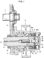
- a valve driving mechanism not belonging to the present invention is provided an intake cam shaft 1 and exhaust cam shaft 2. At one end of the cam shaft 2 is fixed a tubular spacer 3. A driving pulley 4 is mounted over the spacer 3. The driving pulley 4 is provided at one end with a tubular shaped-boss portion 5 extending along the cam shaft 2. The boss portion 5 is formed at a tip end with a reduced portion which is brought into a contact with a tip end portion of the spacer 3 fixed to the cam shaft 2. The other end of the pulley 4 is fixed to one end portion of a tubular joint member 6 which is mounted on the exhaust cam shaft 2 and extends along the cam shaft 2. The joint member 6 is allowed to make a rotative movement relative to the cam shaft 2.
- a first gear 7 is brought into a spline engagement with the other end portion of the tubular joint member 6 and fixed by a lock nut 8.
- the first gear 7 is meshed with a second gear 9 which is fixed at one end of the intake cam shaft 1.
- An annular piston device 10 extending in an axial direction of the cam shaft is incorporated between an inner surface of the boss portion 5 of the pulley 4 and the spacer 3 to cover the spacer 3.
- the piston device 10 is axially split into a front portion 10a and rear portion 10b which are connected with each other by a plurality of pins 11 arranged circumferentially in a spaced relationship from one another by a substantially same distance as shown in Figure 2.
- the piston device 10 is provided with inner helical splines 12 on an inner surface and outer helical splines 13 on an outer surface thereof.
- the inner helical splines 12 is oriented in the opposite direction to the outer helical splines 13 as shown in Figure 3.
- the spacer 3 is provided with helical splines 14 on an outer surface thereof so as to be engaged with the inner helical splines 12.
- the boss portion 5 of the pulley 4 is provided with helical splines 15 on an inner surface thereof so as to be engaged with the outer splines 13.
- the piston device 10 is urged toward the tip end of the cam shaft 2 by a spring 16 disposed between the piston device 10 and an end surface of the joint member 6.
- An oil passage 17 is formed in the exhaust cam shaft along an axial center thereof.
- the tubular spacer 3 is fixed to the exhaust cam shaft 2 through a stopper 18 by means of a bolt member 19.
- the bolt member 19 is formed with a through-hole 20 communicating with the oil passage 17.
- An end plate 22 is mounted on an end surface of the boss portion 5 of the pulley 4 to define an oil chamber 21 facing to a head portion of the piston device 10.
- a hydraulic pressure is introduced into the oil chamber from the oil passage 17 to control movement of the piston in accordance with an engine operating condition.
- a hydraulic control system for controlling the introduction of the hydraulic pressure into the chamber.
- the hydraulic pressure is introduced into the chamber 21 so that an open timing of an exhaust valve is retarded as a result of the phase change in the exhaust cam shaft 2 or a relative rotative movement against the pulley 4. Since a valve timing of an intake valve is constant, an overlap period of the opening of the intake and exhaust valves is increased in the high engine speed condition as shown in Figure 5.
- valve timing varying system in accordance with the present invention is compact as aforementioned.
- the piston device 10 as a valve timing varying system can be incorporated in the intake cam shaft 1.
- the valve timing of the intake valve is advanced in the high engine speed condition as shown in Figure 6.
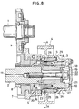
- the joint member 6 of the illustrated embodiment is formed with an extension 7a extending toward the end plate 22.
- the piston device 10 is disposed between the boss portion 5 and the extension 7a.
- the extension 7a is formed with helical splines 14 as formed on the spacer 3 in the former embodiment on an outer surface.
- one end portion of the joint member 6 is inserted into a base portion of the pulley 4 or the boss portion 5.
- the valve driving mechanism is provided with a retainer ring 23 between the joint member 6 and the boss portion 5 for preventing a relative movement between the member 6 and the pulley 4 in the axial direction of the cam shaft 2.
- the retainer ring 23 allows a relative rotative movement between the member 6 and the pulley 4.
- the other end of the joint member 6 is brought into a spline engagement with the first gear 7 and secured to each other by the lock nut 8.
- An inner surface of the boss portion 5 is formed with straight splines 24.
- the joint member 6 is formed with helical splines 25 on an inner surface.
- the spacer 3 is also formed on an outer surface with helical splines 26 in an orientation opposite to that of the helical splines 25 on the joint member 6.
- the annular piston 10 is formed on the outer surface in an axially end portion with straight splines 27 meshing with the straight splines 24 on the inner surface of the boss portion 5, on the outer surface in an axially middle portion with helical splines 28 meshing with the helical splines 25 formed on the inner surface of the joint member 6 and on the inner surface of the middle portion with helical splines 29 meshing with the helical splines 26 formed on the outer surface of the spacer 3.
- the joint member 6 is formed with a stepped portion 30 defining a receiving surface for the spring 16.
- the annular piston 10 is urged toward right in Figure 8. In this structure, the joint member 6 connected to the gear 7, the spacer 3 fixed to the cam shaft 2 and the boss portion 5 of the pulley 4 are connected with each other through the annular piston device 10 so as to make a relative rotative movement to one another.
- the drive pulley 4 may be provided on the intake cam shaft 1 as well.
Landscapes
- Engineering & Computer Science (AREA)
- Mechanical Engineering (AREA)
- General Engineering & Computer Science (AREA)
- Valve Device For Special Equipments (AREA)
- Valve-Gear Or Valve Arrangements (AREA)
Claims (9)
- Ventilsteuermechanismus, mit:einer ersten Nockenwelle (2) zum Antreiben von entweder einem Einlaßventil oder einem Auslaßventil,einer zweiten Nockenwelle (1) zum Antreiben von dem anderen von Einlaß- und Auslaßventil,einer ersten Übertragungseinrichtung (4), welche koaxial an einen Endabschnitt der ersten Nockenwelle (2) zum Übertragen von Antriebsleistung von einer Kurbelwelle zur ersten Nockenwelle (2) vorgesehen ist und welche keine Drehbewegung relativ zu der ersten Nockenwelle (2) ausführen kann,einer zweiten Übertragungseinrichtung (7), welche koaxial an dem einen Endabschnitt der ersten Nockenwelle (2) zum Antreiben der zweiten Nockenwelle (1) vorgesehen ist, dadurch gekennzeichnet, daß die zweite Übertragungseinrichtung (7) eine Drehbewegung relativ zur ersten Übertragungseinrichtung (4) ausführen kann, undmit einer Phasenveränderungseinrichtung, die eine ringförmige Kolbeneinrichtung (10) aufweist, die sich koaxial entlang der ersten Nockenwelle (2) erstreckt zum Variieren einer relativen Drehphase zwischen der ersten und der zweiten Leistungsübertragungseinrichtung (4, 7).
- Ventilsteuermechanismus, mit:einer ersten Nockenwelle (2) zum Antreiben von entweder einem Einlaßventil oder einem Auslaßventil,einer zweiten Nockenwelle (1) zum Antreiben des anderen von Einlaß- und Auslaßventil,einer ersten Übertragungseinrichtung (4), welche koaxial an einem Endabschnitt der ersten Nockenwelle (2) zum Übertragen von Antriebsleistung von einer Kurbelwelle zur ersten Nockenwelle (2) vorgesehen ist,einer zweiten Übertragungseinrichtung (7), welche koaxial an dem einen Endabschnitt der ersten Nockenwelle (2) zum Antreiben der zweiten Nockenwelle (1) vorgesehen ist, dadurch gekennzeichnet, daß die erste Übertragungseinrichtung (4) eine Drehbewegung relativ zur ersten Nockenwelle (2) auführen kann und daß die zweite Übertragungseinrichtung (7) eine Drehbewegung relativ zur ersten Übertragungseinrichtung (4) ausführen kann, undmit einer Phasenveränderungseinrichtung, die eine ringförmige Kolbeneinrichtung (10) aufweist, die sich koaxial entlang der ersten Nockenwelle (2) erstreckt zur Veränderung einer relativen Drehphase zwischen der ersten Übertragungseinrichtung (4) und der ersten Nockenwelle (2) bzw. zwischen der ersten Übertragungseinrichtung (4) und der zweiten Übertragungseinrichtung (7), und zwar auf eine Weise, daß die erste Nockenwelle (2) bezüglich der ersten Übertragungseinrichtung (4) in einer Richtung entgegengesetzt zur zweiten Übertragungseinrichtung (7) gedreht wird.
- Ventilsteuermechanismus nach Anspruch 1, wobei die erste Übertragungseinrichrichtung (4) mit einem Nabenabschnitt (5) versehen ist, welcher sich entlang der ersten Nockenwelle (2) erstreckt, wobei die zweite Übertragungseinrichtung (7) mit einer rohrförmigen Verbindungseinrichtung (6) versehen ist, welche sich entlang der ersten Nockenwelle (2) erstreckt zum Verbinden der zweiten Übertragungseinrichtung (7) mit der ersten Übertragungseinrichtung (4), wobei eine relative Drehbewegung zwischen der ersten und der zweiten Übertragungseinrichtung gestattet ist, wobei die Verbindungseinrichtung (6) eine Drehbewegung relativ zur ersten Nockenwelle (2) ausführen kann, wobei der Nabenabschnitt mit der ersten Nockenwelle (2) verbunden ist, ohne daß er eine Drehbewegung relativ zu der ersten Nockenwelle (2) ausführen kann, wobei die Phasenveränderungseinrichtung zwischen dem Nabenabschnitt und der Verbindungseinrichtung angeordnet ist.
- Ventilsteuermechanismus nach Anspruch 1, wobei die ringförmige Kolbeneinrichtung (10) zwischen der ersten und der zweiten Übertragungseinrichtung angeordnet ist, wobei die Phasenverändungseinrichtung eine erste Eingriffseinrichtung zum Angreifen der ringförmigen Kolbeneinrichtung (10) an der ersten Übertragungseinrichtung (4), eine zweite Eingriffseinrichtung zum Angreifen der ringförmigen Kolbeneinrichtung (10) an der zweiten Übertragungseinrichtung (7) aufweist, wobei die ringförmige Kolbeneinrichtung (10) in axialer Richtung der ersten Nockenwelle (2) bewegt wird, unter Erzeugung einer relativen Drehbewegung zwischen der ersten und der zweiten Übertragungseinrichtung (4, 7).
- Ventilsteuermechanismus nach Anspruch 4, wobei die erste Eingriffseinrichtung schraubenförmige Keilnuten umfaßt, welche an einer äußeren Oberfläche der ringförmigen Kolbeneinrichtung (10) ausgebildet sind, und schraubenförmige Keilnuten umfaßt, welche an einer inneren Oberfläche der ersten Übertragungseinrichtung (4) ausgebildet sind, wobei die schraubenförmigen Keilnuten des ringförmigen Kolbens (10) und die schraubenförmigen Keilnuten der ersten Übertragungseinrichtung (4) miteinander in kämmenden Eingriff gebracht sind und in Richtungen entgegengesetzt zueinander orientiert sind.
- Ventilsteuermechanismus nach Anspruch 4, wobei die zweite Eingriffseinrichtung schraubenförmige Keilnuten aufweist, welche an einer inneren Oberfläche der ringförmigen Kolbeneinrichtung (10) ausgebildet sind, und schraubenförmige Keilnuten aufweist, welche an einer äußeren Oberfläche der zweiten Übertragungseinrichtung (7) ausgebildet sind, wobei die schraubenförmigen Keilnuten des ringförmigen Kolbens (10) und die schraubenförmigen Keilnuten der zweiten Übertragungseinrichtung (7) in kämmenden Eingriff miteinander gebracht sind und in Richtungen entgegengesetzt zueinander orientiert sind.
- Ventilsteuermechanismus nach Anspruch 2, wobei die erste Übertragungseinrichtung (4) mit einem Nabenabschnitt (5) versehen ist, welcher sich entlang der ersten Nockenwelle (2) erstreckt,wobei die zweite Übertragungseinrichtung (7) mit einer rohrförmigen Verbindungseinrichtung (6) versehen ist, welche sich entlang der ersten Nockenwelle (2) erstreckt zum Verbinden der zweiten Übertragungseinrichtung (7) mit der ersten Übertragungseinrichtung (4) unter Zulassung einer relativen Drehbewegung zwischen der ersten und der zweiten Übertragungseinrichtung,wobei die Verbindungseinrichtung (6) eine Drehbewegung relativ zu sowohl dem Nabenabschnitt (5) als auch der ersten Nockenwelle (2) ausführen kann,wobei die ringförmige Kolbeneinrichtung zwischen der ersten Nockenwelle (2) und der Verbindungseinrichtung (6) und zwischen der ersten Nockenwelle (2) und dem Nabenabschnitt (5) angeordnet ist und wobei die Phasenveränderungseinrichtung Endeingriffseinrichtungen zum Angreifen eines Endabschnittes der ringförmigen Kolbeneinrichtung (10) an dem Nabenabschnitt (5), eine erste Mitteleingriffseinrichtung zum Angreifen eines mittleren Abschnittes der ringförmigen Kolbeneinrichtung (10) an der Verbindungseinrichtung (6) und eine zweite Mitteleingriffseinrichtung zum Angreifen der ersten Nockenwelle (2) an einem mittleren Abschnitt der ringförmigen Kolbeneinrichtung (10) aufweist,wobei die erste Mitteleingriffseinrichtung eine Drehbewegung der Verbindungseinrichtung (6) relativ zu der ringförmigen Kolbeneinrichtung (10) aufgrund der axialen Bewegung der ringförmigen Kolbeneinrichtung (10) erzeugt,wobei die zweite Mitteleingriffseinrichtung eine Drehbewegung der ersten Nockenwelle (2) relativ zu der ringförmigen Kolbeneinrichtung (10) aufgrund einer axialen Bewegung der ringförmigen Kolbeneinrichtung (10) erzeugt,wobei die Drehbewegung zwischen der ringförmigen Kolbeneinrichtung (10) und der ersten Nockenwelle (2) in einer Richtung umgekehrt zu jener zwischen der ringförmigen Kolbeneinrichtung (10) und dem Nabenabschnitt (5) erzeugt wird.
- Ventilsteuermechanismus nach Anspruch 7, wobei die Endeingriffseinrichtung äußere gerade Endkeilnuten aufweist, welche an einer äußeren Oberfläche eines Endabschnittes der ringförmigen Kolbeneinrichtung (10) ausgebildet sind, und innere gerade Keilnuten aufweist, welche an einer inneren Oberfläche des Nabenabschnittes (5) ausgebildet sind,wobei die äußeren geraden Endkeilnuten in kämmenden Eingriff mit den inneren geraden Keilnuten ohne Erzeugung einer relativen Drehbewegung zwischen diesen unabhängig von der axialen Bewegung der ringförmigen Kolbeneinrichtung (10) gebracht sind,wobei die erste Mitteleingriffseinrichtung mittlere äußere schraubenförmige Keilnuten aufweist, welche an einer äußeren Oberfläche eines mittleren Abschnittes der ringförmigen Kolbeneinrichtung (10) ausgebildet sind, und innere schraubenförmige Keilnuten aufweist, welche an einer inneren Oberfläche der Verbindungseinrichtung (6) ausgebildet sind,wobei die mittleren äußeren schraubenförmigen Keilnuten der ringförmigen Kolbeneinrichtung (10) in kämmenden Eingriff mit den inneren schraubenförmigen Keilnuten der Verbindungseinrichtung (6) unter Erzeugung der relativen Drehbewegung zwischen diesen aufgrund der axialen Bewegung der ringförmigen Kolbeneinrichtung (10) gebracht sind,wobei die zweite Mitteleingriffseinrichtung mittlere innere schraubenförmige Keilnuten aufweist, welche an einer inneren Oberfläche der ringförmigen Kolbeneinrichtung (10) ausgebildet sind, und äußere schraubenförmige Keilnuten aufweist, welche an einer äußeren Oberfläche der ersten Nockenwelle (2) ausgebildet sind,wobei die mittleren inneren schraubenförmigen Keilnuten in kämmenden Eingriff mit den äußeren schraubenförmigen Keilnuten der ersten Nockenwelle (2) unter Erzeugung der relativen Drehbewegung zwischen diesen gebracht ist,wobei die mittleren äußeren schraubenförmigen Keilnuten in einer Richtung entgegengesetzt zu jener der mittleren inneren schraubenförmigen Keilnuten orientiert sind.
- Ventilsteuermechanismus nach einem der Ansprüche 1 bis 8, wobei die ringförmige Kolbeneinrichtung zur Erzeugung der Axialbewegung durch einen Hydraulikdruck gesteuert wird.
Applications Claiming Priority (4)
| Application Number | Priority Date | Filing Date | Title |
|---|---|---|---|
| JP274258/88 | 1988-10-29 | ||
| JP27425988A JP2745310B2 (ja) | 1988-10-29 | 1988-10-29 | エンジンの動弁装置 |
| JP274259/88 | 1988-10-29 | ||
| JP63274258A JP2620129B2 (ja) | 1988-10-29 | 1988-10-29 | エンジンの動弁装置 |
Publications (2)
| Publication Number | Publication Date |
|---|---|
| EP0367192A1 EP0367192A1 (de) | 1990-05-09 |
| EP0367192B1 true EP0367192B1 (de) | 1996-01-03 |
Family
ID=26550963
Family Applications (1)
| Application Number | Title | Priority Date | Filing Date |
|---|---|---|---|
| EP89120119A Expired - Lifetime EP0367192B1 (de) | 1988-10-29 | 1989-10-30 | Ventilantriebsvorrichtung für Brennkraftmaschine |
Country Status (3)
| Country | Link |
|---|---|
| US (1) | US4993370A (de) |
| EP (1) | EP0367192B1 (de) |
| DE (1) | DE68925342T2 (de) |
Families Citing this family (17)
| Publication number | Priority date | Publication date | Assignee | Title |
|---|---|---|---|---|
| JP2741266B2 (ja) * | 1989-12-18 | 1998-04-15 | マツダ株式会社 | エンジンの吸排気制御装置 |
| US5181485A (en) * | 1990-03-29 | 1993-01-26 | Mazda Motor Corporation | Valve driving mechanism for double overhead camshaft engine |
| JPH05209505A (ja) * | 1992-01-31 | 1993-08-20 | Aisin Seiki Co Ltd | 2軸間位相変換装置 |
| US5184578A (en) * | 1992-03-05 | 1993-02-09 | Borg-Warner Automotive Transmission & Engine Components Corporation | VCT system having robust closed loop control employing dual loop approach having hydraulic pilot stage with a PWM solenoid |
| US5289805A (en) * | 1992-03-05 | 1994-03-01 | Borg-Warner Automotive Transmission & Engine Components Corporation | Self-calibrating variable camshaft timing system |
| JPH0642316A (ja) * | 1992-05-29 | 1994-02-15 | Nippondenso Co Ltd | 内燃機関のバルブタイミング調整装置 |
| US5233948A (en) * | 1992-12-10 | 1993-08-10 | Ford Motor Company | Variable cycle engine |
| US5327859A (en) * | 1993-06-09 | 1994-07-12 | General Motors Corporation | Engine timing drive with fixed and variable phasing |
| US5417186A (en) * | 1993-06-28 | 1995-05-23 | Clemson University | Dual-acting apparatus for variable valve timing and the like |
| JP2982581B2 (ja) * | 1993-10-14 | 1999-11-22 | 日産自動車株式会社 | 内燃機関の可変動弁装置 |
| JP3385717B2 (ja) * | 1994-05-02 | 2003-03-10 | 日産自動車株式会社 | 内燃機関の可変動弁装置 |
| US5657725A (en) * | 1994-09-15 | 1997-08-19 | Borg-Warner Automotive, Inc. | VCT system utilizing engine oil pressure for actuation |
| US5542383A (en) * | 1995-05-04 | 1996-08-06 | Ford Motor Company | Dual output camshaft phase controller |
| JPH09310607A (ja) * | 1996-05-21 | 1997-12-02 | Toyota Motor Corp | 内燃機関のバルブタイミング可変機構 |
| DE19701202A1 (de) * | 1997-01-15 | 1998-07-23 | Daimler Benz Ag | Variable Ventilsteuerung für Brennkraftmaschinen |
| WO2006047099A2 (en) | 2004-10-26 | 2006-05-04 | George Louie | Continuously variable valve timing device |
| GB201210894D0 (en) * | 2012-06-20 | 2012-08-01 | Goodrich Control Sys | Angular positioning arrangement |
Citations (5)
| Publication number | Priority date | Publication date | Assignee | Title |
|---|---|---|---|---|
| US4305367A (en) * | 1978-08-31 | 1981-12-15 | Hino Jidosha Kogyo Kabushiki Kaisha | Injection timing control system for fuel-injection pump for engine |
| US4535731A (en) * | 1982-05-17 | 1985-08-20 | Alfa Romeo Auto S.P.A. | Device for automatically varying the timing of a camshaft |
| US4674452A (en) * | 1985-05-29 | 1987-06-23 | Mazda Motor Corporation | Camshaft driving system for internal combustion engine |
| EP0254058A2 (de) * | 1986-07-23 | 1988-01-27 | Süddeutsche Kolbenbolzenfabrik GmbH | Nockenwelle zum Steuern der Gasein- und Auslassventile von Verbrennungsmotoren |
| WO1988006677A1 (en) * | 1987-02-24 | 1988-09-07 | Allied-Signal Inc. | Variable camshaft timing system |
Family Cites Families (10)
| Publication number | Priority date | Publication date | Assignee | Title |
|---|---|---|---|---|
| IT1093715B (it) * | 1978-03-24 | 1985-07-26 | Alfa Romeo Spa | Variatore di fase della distribuzione per motore alternativo a combustione interna |
| IT1150995B (it) * | 1980-07-31 | 1986-12-17 | Alfa Romeo Spa | Variatore automatico di fase per motore a combustione interna |
| JPS58135310A (ja) * | 1982-02-08 | 1983-08-11 | Toyota Motor Corp | 内燃機関のバルブタイミング制御装置 |
| US4601266A (en) * | 1983-12-30 | 1986-07-22 | Renold Plc | Phasing device for machine applications |
| JPS60153411A (ja) * | 1984-01-20 | 1985-08-12 | Mazda Motor Corp | デイ−ゼルエンジンの吸気弁制御装置 |
| JPH0219521Y2 (de) * | 1985-04-17 | 1990-05-30 | ||
| US4811698A (en) * | 1985-05-22 | 1989-03-14 | Atsugi Motor Parts Company, Limited | Valve timing adjusting mechanism for internal combustion engine for adjusting timing of intake valve and/or exhaust valve corresponding to engine operating conditions |
| DE3638087A1 (de) * | 1986-11-07 | 1988-05-11 | Porsche Ag | Vorrichtung zur beeinflussung der steuerzeiten von ventilen |
| JPS63230917A (ja) * | 1987-03-18 | 1988-09-27 | Fuji Heavy Ind Ltd | ダブルオ−バ−ヘツドカムエンジンのバルブタイミング変更装置 |
| US4862843A (en) * | 1987-06-23 | 1989-09-05 | Honda Giken Kogyo Kabushiki Kaisha | Valve timing control device for use in internal combustion engine |
-
1989
- 1989-10-27 US US07/427,471 patent/US4993370A/en not_active Expired - Lifetime
- 1989-10-30 DE DE68925342T patent/DE68925342T2/de not_active Expired - Lifetime
- 1989-10-30 EP EP89120119A patent/EP0367192B1/de not_active Expired - Lifetime
Patent Citations (5)
| Publication number | Priority date | Publication date | Assignee | Title |
|---|---|---|---|---|
| US4305367A (en) * | 1978-08-31 | 1981-12-15 | Hino Jidosha Kogyo Kabushiki Kaisha | Injection timing control system for fuel-injection pump for engine |
| US4535731A (en) * | 1982-05-17 | 1985-08-20 | Alfa Romeo Auto S.P.A. | Device for automatically varying the timing of a camshaft |
| US4674452A (en) * | 1985-05-29 | 1987-06-23 | Mazda Motor Corporation | Camshaft driving system for internal combustion engine |
| EP0254058A2 (de) * | 1986-07-23 | 1988-01-27 | Süddeutsche Kolbenbolzenfabrik GmbH | Nockenwelle zum Steuern der Gasein- und Auslassventile von Verbrennungsmotoren |
| WO1988006677A1 (en) * | 1987-02-24 | 1988-09-07 | Allied-Signal Inc. | Variable camshaft timing system |
Also Published As
| Publication number | Publication date |
|---|---|
| US4993370A (en) | 1991-02-19 |
| DE68925342T2 (de) | 1996-06-27 |
| DE68925342D1 (de) | 1996-02-15 |
| EP0367192A1 (de) | 1990-05-09 |
Similar Documents
| Publication | Publication Date | Title |
|---|---|---|
| EP0367192B1 (de) | Ventilantriebsvorrichtung für Brennkraftmaschine | |
| US5992361A (en) | Variable valve timing mechanism | |
| EP0512699B1 (de) | Steuervorrichtung für die Winkelverstellung einer Nockenwelle bei einer Brennkraftmaschine | |
| EP0675265B1 (de) | Ventilantriebssystem für eine interne brennkraftmaschine | |
| EP0741235B1 (de) | Doppelausgangs-Nockenwellenphasenregler | |
| US4974560A (en) | Mechanism for varying valve duration in an internal combustion engine | |
| US5355849A (en) | Automatic variator valve overlap or timing and valve section | |
| US5893345A (en) | Valve control apparatus for an internal combustion engine | |
| US5121717A (en) | Internal combustion engine camshaft phase shift control system | |
| JPH0886206A (ja) | トルク伝達装置 | |
| JPH08296413A (ja) | 弁開閉時期制御装置 | |
| JPH07279632A (ja) | 内燃機関のカム軸位相可変装置 | |
| JPH09310607A (ja) | 内燃機関のバルブタイミング可変機構 | |
| GB2308636A (en) | Valve timing adjustment device for internal combustion engine | |
| JP3562075B2 (ja) | 弁開閉時期制御装置 | |
| JP2551823Y2 (ja) | 内燃機関のバルブタイミング制御装置 | |
| JP2878252B2 (ja) | エンジンの動弁装置 | |
| JP2745310B2 (ja) | エンジンの動弁装置 | |
| KR20010059127A (ko) | 가변 밸브 타이밍 장치 | |
| EP0793003B1 (de) | Variable Steuervorrichtung für den Ventilbetrieb einer Brennkraftmaschine | |
| JP2544108B2 (ja) | 内燃機関における異種カム軸間の位相調整装置 | |
| JPS6321309A (ja) | 内燃機関のタイミング管制カム | |
| JPH07180510A (ja) | 内燃機関のバルブタイミング調整装置 | |
| JPH0941919A (ja) | 弁開閉時期制御装置 | |
| JPH08334006A (ja) | 内燃機関のバルブタイミング制御装置 |
Legal Events
| Date | Code | Title | Description |
|---|---|---|---|
| PUAI | Public reference made under article 153(3) epc to a published international application that has entered the european phase |
Free format text: ORIGINAL CODE: 0009012 |
|
| AK | Designated contracting states |
Kind code of ref document: A1 Designated state(s): DE FR GB |
|
| 17P | Request for examination filed |
Effective date: 19900907 |
|
| 17Q | First examination report despatched |
Effective date: 19911122 |
|
| GRAA | (expected) grant |
Free format text: ORIGINAL CODE: 0009210 |
|
| AK | Designated contracting states |
Kind code of ref document: B1 Designated state(s): DE FR GB |
|
| REF | Corresponds to: |
Ref document number: 68925342 Country of ref document: DE Date of ref document: 19960215 |
|
| ET | Fr: translation filed | ||
| PLBE | No opposition filed within time limit |
Free format text: ORIGINAL CODE: 0009261 |
|
| STAA | Information on the status of an ep patent application or granted ep patent |
Free format text: STATUS: NO OPPOSITION FILED WITHIN TIME LIMIT |
|
| 26N | No opposition filed | ||
| PGFP | Annual fee paid to national office [announced via postgrant information from national office to epo] |
Ref country code: FR Payment date: 19991011 Year of fee payment: 11 |
|
| PGFP | Annual fee paid to national office [announced via postgrant information from national office to epo] |
Ref country code: GB Payment date: 19991027 Year of fee payment: 11 |
|
| PG25 | Lapsed in a contracting state [announced via postgrant information from national office to epo] |
Ref country code: GB Free format text: LAPSE BECAUSE OF NON-PAYMENT OF DUE FEES Effective date: 20001030 |
|
| GBPC | Gb: european patent ceased through non-payment of renewal fee |
Effective date: 20001030 |
|
| PG25 | Lapsed in a contracting state [announced via postgrant information from national office to epo] |
Ref country code: FR Free format text: LAPSE BECAUSE OF NON-PAYMENT OF DUE FEES Effective date: 20010629 |
|
| REG | Reference to a national code |
Ref country code: FR Ref legal event code: ST |
|
| PGFP | Annual fee paid to national office [announced via postgrant information from national office to epo] |
Ref country code: DE Payment date: 20081027 Year of fee payment: 20 |