EP0348971B1 - Verrou relâché lors de la fermeture d'une porte, notamment pour crémone de porte, fenêtre, etc. - Google Patents
Verrou relâché lors de la fermeture d'une porte, notamment pour crémone de porte, fenêtre, etc. Download PDFInfo
- Publication number
- EP0348971B1 EP0348971B1 EP89111848A EP89111848A EP0348971B1 EP 0348971 B1 EP0348971 B1 EP 0348971B1 EP 89111848 A EP89111848 A EP 89111848A EP 89111848 A EP89111848 A EP 89111848A EP 0348971 B1 EP0348971 B1 EP 0348971B1
- Authority
- EP
- European Patent Office
- Prior art keywords
- driven bolt
- latch
- lock
- fastener according
- clamping plate
- Prior art date
- Legal status (The legal status is an assumption and is not a legal conclusion. Google has not performed a legal analysis and makes no representation as to the accuracy of the status listed.)
- Expired - Lifetime
Links
- 229910000831 Steel Inorganic materials 0.000 claims description 5
- 239000010959 steel Substances 0.000 claims description 5
- 230000000149 penetrating effect Effects 0.000 claims description 4
- 238000002347 injection Methods 0.000 claims description 3
- 239000007924 injection Substances 0.000 claims description 3
- 239000002991 molded plastic Substances 0.000 claims description 3
- 230000006835 compression Effects 0.000 abstract description 6
- 238000007906 compression Methods 0.000 abstract description 6
- 238000006073 displacement reaction Methods 0.000 abstract description 3
- 238000003780 insertion Methods 0.000 abstract 1
- 230000037431 insertion Effects 0.000 abstract 1
- 238000009434 installation Methods 0.000 description 5
- 239000002184 metal Substances 0.000 description 2
- 230000002787 reinforcement Effects 0.000 description 2
- 229910000760 Hardened steel Inorganic materials 0.000 description 1
- 238000010276 construction Methods 0.000 description 1
- 238000004512 die casting Methods 0.000 description 1
- 238000005495 investment casting Methods 0.000 description 1
- 238000004519 manufacturing process Methods 0.000 description 1
- 239000000463 material Substances 0.000 description 1
- 238000000034 method Methods 0.000 description 1
- 238000012986 modification Methods 0.000 description 1
- 230000004048 modification Effects 0.000 description 1
- 230000003313 weakening effect Effects 0.000 description 1
- 238000004804 winding Methods 0.000 description 1
Images

Classifications
-
- E—FIXED CONSTRUCTIONS
- E05—LOCKS; KEYS; WINDOW OR DOOR FITTINGS; SAFES
- E05B—LOCKS; ACCESSORIES THEREFOR; HANDCUFFS
- E05B47/00—Operating or controlling locks or other fastening devices by electric or magnetic means
- E05B47/02—Movement of the bolt by electromagnetic means; Adaptation of locks, latches, or parts thereof, for movement of the bolt by electromagnetic means
- E05B47/026—Movement of the bolt by electromagnetic means; Adaptation of locks, latches, or parts thereof, for movement of the bolt by electromagnetic means the bolt moving rectilinearly
-
- E—FIXED CONSTRUCTIONS
- E05—LOCKS; KEYS; WINDOW OR DOOR FITTINGS; SAFES
- E05B—LOCKS; ACCESSORIES THEREFOR; HANDCUFFS
- E05B47/00—Operating or controlling locks or other fastening devices by electric or magnetic means
- E05B47/0001—Operating or controlling locks or other fastening devices by electric or magnetic means with electric actuators; Constructional features thereof
- E05B47/0002—Operating or controlling locks or other fastening devices by electric or magnetic means with electric actuators; Constructional features thereof with electromagnets
-
- E—FIXED CONSTRUCTIONS
- E05—LOCKS; KEYS; WINDOW OR DOOR FITTINGS; SAFES
- E05B—LOCKS; ACCESSORIES THEREFOR; HANDCUFFS
- E05B63/00—Locks or fastenings with special structural characteristics
- E05B63/18—Locks or fastenings with special structural characteristics with arrangements independent of the locking mechanism for retaining the bolt or latch in the retracted position
- E05B63/20—Locks or fastenings with special structural characteristics with arrangements independent of the locking mechanism for retaining the bolt or latch in the retracted position released automatically when the wing is closed
-
- E—FIXED CONSTRUCTIONS
- E05—LOCKS; KEYS; WINDOW OR DOOR FITTINGS; SAFES
- E05C—BOLTS OR FASTENING DEVICES FOR WINGS, SPECIALLY FOR DOORS OR WINDOWS
- E05C9/00—Arrangements of simultaneously actuated bolts or other securing devices at well-separated positions on the same wing
- E05C9/18—Details of fastening means or of fixed retaining means for the ends of bars
- E05C9/1808—Keepers
-
- E—FIXED CONSTRUCTIONS
- E05—LOCKS; KEYS; WINDOW OR DOOR FITTINGS; SAFES
- E05C—BOLTS OR FASTENING DEVICES FOR WINGS, SPECIALLY FOR DOORS OR WINDOWS
- E05C9/00—Arrangements of simultaneously actuated bolts or other securing devices at well-separated positions on the same wing
- E05C9/18—Details of fastening means or of fixed retaining means for the ends of bars
- E05C9/1825—Fastening means
- E05C9/1833—Fastening means performing sliding movements
- E05C9/185—Fastening means performing sliding movements parallel with actuating bar
-
- E—FIXED CONSTRUCTIONS
- E05—LOCKS; KEYS; WINDOW OR DOOR FITTINGS; SAFES
- E05B—LOCKS; ACCESSORIES THEREFOR; HANDCUFFS
- E05B47/00—Operating or controlling locks or other fastening devices by electric or magnetic means
- E05B47/0001—Operating or controlling locks or other fastening devices by electric or magnetic means with electric actuators; Constructional features thereof
- E05B47/0002—Operating or controlling locks or other fastening devices by electric or magnetic means with electric actuators; Constructional features thereof with electromagnets
- E05B47/0003—Operating or controlling locks or other fastening devices by electric or magnetic means with electric actuators; Constructional features thereof with electromagnets having a movable core
- E05B47/0004—Operating or controlling locks or other fastening devices by electric or magnetic means with electric actuators; Constructional features thereof with electromagnets having a movable core said core being linearly movable
-
- E—FIXED CONSTRUCTIONS
- E05—LOCKS; KEYS; WINDOW OR DOOR FITTINGS; SAFES
- E05B—LOCKS; ACCESSORIES THEREFOR; HANDCUFFS
- E05B53/00—Operation or control of locks by mechanical transmissions, e.g. from a distance
- E05B53/003—Operation or control of locks by mechanical transmissions, e.g. from a distance flexible
Definitions
- the invention relates to a drive bolt switch lock, in particular for drive rod locks on door or the like.
- Wings with a lock faceplate with a passage opening provided therein for the lock housing having spring-loaded drive bolts in the direction of its extended locking position, a spring-loaded clamping plate accommodated therein. which engages around the drive bolt with a clamping eye and allows it to be blocked in any retracted position, as well as with a spring latch which also penetrates the lock faceplate and is to be pressed in when it hits the door frame and thereby pivots the clamping plate into its release position releasing the drive bolt.
- Driving bolt switch locks of the above type are known from DE-PS 27 46 049 and DE-PS 29 12 881. They are usually installed in the passive leaf of double-leaf doors, e.g. B. according to DE-GM 87 01 630 to ensure that the spring bolt under spring force is held in its unlocked position with the wing open and only extends into its locking position after the passive leaf has reached its closed position. The outer end of the drive bolt then engages in the locking hole of a striking plate on the fixed door frame, which also serves as a stop for the switch latch. Of particular importance is the clamping plate housed in the lock housing, which not only allows the drive bolt to be locked in its fully retracted position but also in any other retracted position. This is important because the drive bar rods at z.
- the invention is therefore based on the object of improving and perfecting a drive bolt switch lock of the type mentioned at the outset in that it is of an even simpler and also space-saving design and can be mounted much more easily in door or the like.
- This object is essentially achieved in that the switch latch with one in its direction of displacement continuous cavity is provided through which the drive bolt is to be inserted.
- This coaxial arrangement of the switching latch and drive bolt results in a compact construction of the switching lock, which not only simplifies its manufacture but also extremely simplifies its installation.
- the lock housing and the switching latch are of hollow-cylindrical design and, together with the correspondingly annular clamping plate and a compression spring acting thereon, are arranged concentrically with the drive bolt to be pushed through them in the center.
- the switch latch can rest with its inner end face directly on the resiliently supported clamping plate, so that a special switch latch spring is unnecessary.
- the switch latch in its hollow cylindrical design, when it hits the striking plate struck on the door frame side, cannot move into the locking hole like the drive bolt rod, supporting wings which protrude laterally are advantageously provided on the outer beveled end of the switch latch.
- the passage opening in the lock faceplate can also have a contour corresponding to the switching latch profile and its supporting wings.
- the switch latch can be snap-fastened and guided against rotation in the lock housing via a spring projection on the side of it, which projects into a longitudinal slot of the lock housing and is guided therein.
- the switch latch can advantageously consist of injection molded plastic.
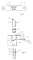
- the switching lock has a lock housing 4 which is connected to the lock face plate 3 and which is designed as a hollow cylinder.
- the lock housing 4 can advantageously consist of appropriately rolled steel sheet, which with the z. B. made of stamped sheet metal 3, z. B. is welded, soldered or riveted.
- the correspondingly cylindrical switching latch 5, the essentially ring-shaped clamping plate 6 and the clamping plate compression spring 7 are accommodated.
- the switch latch 5 is provided with a cavity 5 'running continuously in its direction of displacement, through which the drive bolt 2 is to be inserted or which it penetrates axially displaceably in the installed position.
- the bolt 2 of the switch latch 5, the clamping plate 6 and also the compression spring 7 as well as overall of the lock housing 4 tightly enveloped concentrically, resulting in an extremely space-saving design for the switching lock.
- the annular clamping plate 6 is provided on its outer circumference with guide cams 6 ', via which it is guided in the cylindrical lock housing 4 existing longitudinal slots 4' against rotation.
- the helical compression spring 7 acting on it is supported at its lower end by support tabs 4 ⁇ which are bent out inwards from the lock housing 4. It strives to press the clamping plate 6 over the angled guide cams 6 'in their tilted locking position shown in Fig. 1, in which it allows to block the driving bolt in any retracted position with its clamping eye 2' clamping eye 6 '.
- the clamping plate 6 is supported with its guide cam 6 links shown in Fig. 1 on the existing on the lock housing 4, the associated longitudinal slot 4 'limiting stop 4 ′.
- the hollow cylindrical switching latch 5 is advantageously made of injection molded plastic, although in principle it is also made of another material, eg. B. can consist of die casting, investment casting or sintered metal.
- a laterally arranged resilient projection 5 ' which, when the switching latch 5 is inserted into the lock housing 4 in the upper section 4 IV of a longitudinal slot 4', jumps in and thereby the case 5 leads both torsionally in the lock housing 4, and in cooperation with the attacked by the resilient projection 5 'stop 3' on the lock face plate 3 limits the extension movement of the switching latch 5.
- the lock face plate 3 there is a passage opening 3 'for the switching latch 5 and the drive bolt 2 penetrating it, which essentially corresponds to the inside diameter of the lock housing 4.
- the trap 5 On the outside with a corresponding sloping surface 5 5
- the trap 5 is provided with support wings 5 IV projecting on both sides. They prevent the switching latch 5 in the closing position of the door leaf 1 shown in FIGS. 3 and 4 also approximately into the closing opening 8 'of the striking plate 8 arranged on the fixed frame 9. So that the switch latch 5 at z. B. close door rebate air can fully retract into the lock face plate 3, the passage opening 3ae present in the latter is advantageously contoured so that it corresponds to the switch latch profile in addition to the support wings 5 IV present on the switch latch.
- the driving bolt partially shown in Fig. 6 below advantageously consists of steel tube 2 ', in the upper end to be blocked by the switching lock and its clamping plate 6 the preferably made of hardened steel bolt 2' is inserted. Due to the cone 2aen present at the outer end, the entry of the drive bolt into the striking plate opening 8 'is facilitated.
- the compression spring 7 is inserted into the lock housing 4, with its lower end being supported on the support tab 4 ⁇ .
- the clamping plate 6 is then inserted radially through the transverse slot 4 V present in the lock housing 4 and extending approximately over half its width in the direction of the arrow shown until the guide cam 6 6 comes under the limit stop 4 ′′′.
- the switch latch 5 is inserted into the lock housing 4, until it jumps with its resilient projection 5 'behind the stop 3 present on the lock face plate 3', i.e. also in the upper part 4 IV of the right in Fig. 6 existing longitudinal slot 4 '.
- the key switch can be inserted into a hole that is easy to make in the door leaf, and then the locking bar 2 can be installed. Due to the cylindrical compact design of the key switch, the lock housing of which can have an outer diameter of less than 19 mm, this requires installation Switch lock only a hole with a diameter of 20 mm.
- Another major advantage of this narrow-action driving bolt switch lock is that its clamping plate 6 allows only slight springback of the driving bolt rod 2. As a result, the push-in stroke of the switching latch required to release the clamping plate has become considerably shorter than in the previous design. This in turn also makes it possible to dispense with the adjustability of the switch latch described in DE-PS 29 12 881, especially since the usable latch stroke has also been increased in that the clamping plate no longer hits against a stop during the inward movement in the opening direction.
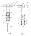
- the lock housing 4 is provided internally with a housing extension 10 lying coaxially to it, in which the spring 11, which tries to press the drive bolt 2 into its illustrated, extended locking position, is accommodated, the upper end of which is connected to the drive rod 2, for example at the gag 12, engages and is supported with its other lower end on which the passage opening 10 'for the driving bolt 2 limiting housing edge 10'.
- the bolt 2 by a serving as an actuating force mechanical pull connection means for.
- a cable or chain hoist 13 can be retracted against the action of its spring 11, for example via an actuating handle, for example via an end (not shown) of the traction cable 13.
- an electromagnet 14 is attached to the housing extension 10 as an actuating force attack instead of the manual train connection for releasing the door leaf.
- the electromagnet 14 engages the drive bolt 2 in its the door leaf when its coil winding flows through 1 releasing entry position is able to pull.
- the housing extension 10 can be easily or with the like in the lower ends of the longitudinal slots 4 'on the lock housing snapping bracket.
- other connection options are possible between the two housing parts, in particular also a one-piece design of the lock housing 4 and extension 10.
- the new drive bolt key switch not only needs to be combined with a drive rod lock housed in the passive leaf of double-leaf doors, but that it can also be easily installed in single-leaf doors or also in sliding doors and the like.
Landscapes
- Engineering & Computer Science (AREA)
- Mechanical Engineering (AREA)
- Physics & Mathematics (AREA)
- Electromagnetism (AREA)
- Structural Engineering (AREA)
- Lock And Its Accessories (AREA)
- Push-Button Switches (AREA)
- Specific Sealing Or Ventilating Devices For Doors And Windows (AREA)
- Securing Of Glass Panes Or The Like (AREA)
Claims (14)
- Serrure de manoeuvre à verrou de commande pour des fermetures à tige de commande sur des vantaux de porte ou d'éléments semblables, avec un coffre de serrure (4) présentant une têtière (3) avec une ouverture de passage (3'') qui y est prévue pour le verrou de commande (2) sollicité par ressort dans le sens de sa position de verrouillage sortie, une plaque de blocage (6) à ressort logée à l'intérieur qui entoure le verrou de commande (2) par un oeil de blocage (6'') et permet de le bloquer dans des positions quelconques, ainsi qu'avec un pêne demi-tour (5) traversant également la têtière (3) et sollicité par ressort, et qui doit rentrer lorsqu'il arrive contre l'encadrement de porte et fait ainsi pivoter la plaque de blocage (6) dans sa position de déblocage libérant le verrou de commande (2), caractérisée en ce que le pêne demi-tour (5) est muni d'une cavité (5') qui s'étend de bout en bout dans son sens de déplacement et dans laquelle doit passer le verrou de commande (2).
- Serrure de manoeuvre à verrou de commande selon la revendication 1, caractérisée en ce que le coffre de serrure (4) et le pêne demi-tour (5) sont configurés sous la forme de cylindres creux et disposés, avec la plaque de blocage (6) configurée annulairement en conséquence et un ressort de pression (7) qui la sollicite, de manière concentrique par rapport au verrou de commande (2) qui traverse tous ces éléments au centre.
- Serrure de manoeuvre à verrou de commande selon la revendication 2, caractérisée en ce que le pêne demitour (5) s'appuie directement par son extrémité frontale intérieure contre la plaque de blocage (6).
- Serrure de manoeuvre à verrou de commande selon la revendication 2, caractérisée en ce que la plaque de blocage (6) annulaire est guidée antirotation par des cames de guidage (6', 6''') présentes sur sa périphérie extérieure, dans des fentes longitudinales (4') présentes dans le coffre de serrure (4) cylindrique.
- Serrure de manoeuvre à verrou de commande selon l'une quelconque des revendications 1 à 4, caractérisée en ce que le pêne demi-tour (5) est muni latéralement d'ailes d'appui (5IV) en porte à faux sur son extrémité extérieure (5''') biseautée.
- Serrure de manoeuvre à verrou de commande selon la revendication 5, caractérisée en ce que l'ouverture de passage (3'') présente dans la têtière (3) possède un contour correspondant au profil du pêne demi-tour et de ses ailes d'appui (5IV).
- Serrure de manoeuvre à verrou de commande selon l'une quelconque des revendications 1 à 6, caractérisée en ce que le pêne demi-tour (5) est fixé de manière encliquetable dans le coffre de serrure (4), par l'intermédiaire d'une saillie (5'') faisant ressort latéralement présente sur lui, qui s'enclenche avec une fente longitudinale (4') du coffre de serrure (4) et qui y est guidée, et il est ainsi guidé sans risque de rotation.
- Serrure de manoeuvre à verrou de commande selon la revendication 7, caractérisée en ce que le pêne demi-tour (5) se compose de matière plastique moulée par injection.
- Serrure de manoeuvre à verrou de commande selon la revendication 2, caractérisée en ce que le ressort de pression (7) qui vient en contact avec la plaque de blocage (6) s'appuie par son autre extrémité sur des languettes de support (4'') repliées vers l'intérieur à partir du coffre de serrure (4).
- Serrure de manoeuvre à verrou de commande selon l'une quelconque des revendications 1 à 9, caractérisée en ce que le coffre de serrure (4) consiste en une tôle d'acier roulée en conséquence, qui est reliée à la têtière (3).
- Serrure de manoeuvre à verrou de commande selon l'une quelconque des revendications 1 à 10, caractérisée en ce que le coffre de serrure (4) est muni en bas d'un prolongement de coffre (10) situé de manière coaxiale par rapport à lui, et dans lequel est logé le ressort (11) tendant à pousser vers la position de verrouillage sortie du verrou de commande (2) et en ce qu'en outre, un élément de manoeuvre, agissant contre le ressort (11) du verrou de commande, est présent à l'extrémité inférieure du verrou de commande (2) traversant le prolongement de coffre (10).
- Serrure de manoeuvre à verrou de commande selon la revendication 11, caractérisée en ce qu'un moyen de tirage mécanique (13, figure 7), par exemple un tirant à câble ou à chaîne, en prise avec l'extrémité du verrou de commande, sert d'élément de manoeuvre.
- Serrure de manoeuvre à verrou de commande selon la revendication 11, caractérisée en ce qu'un électroaimant (14, figure 8) en contact avec l'extrémité intérieure du verrou de commande sert d'élément de manoeuvre.
- Serrure de manoeuvre à verrou de commande selon l'une quelconque des revendications 1 à 13, caractérisée en ce que le verrou de commande (2) consiste en un tube d'acier (2'), à l'extrémité extérieure duquel est enfoncé un verrou d'acier (2'', figure 6) qui s'effile en cône.
Priority Applications (1)
| Application Number | Priority Date | Filing Date | Title |
|---|---|---|---|
| AT89111848T ATE86348T1 (de) | 1988-07-01 | 1989-06-29 | Treibriegel-schaltschloss, insbesondere fuer treibstangenverschluesse an tuerod.dgl.-fl¨geln. |
Applications Claiming Priority (2)
| Application Number | Priority Date | Filing Date | Title |
|---|---|---|---|
| DE3822286A DE3822286A1 (de) | 1988-07-01 | 1988-07-01 | Treibriegel-schaltschloss, insbesondere fuer treibstangenverschluesse an tuer- od. dgl. -fluegeln |
| DE3822286 | 1988-07-01 |
Publications (3)
| Publication Number | Publication Date |
|---|---|
| EP0348971A2 EP0348971A2 (fr) | 1990-01-03 |
| EP0348971A3 EP0348971A3 (en) | 1990-09-05 |
| EP0348971B1 true EP0348971B1 (fr) | 1993-03-03 |
Family
ID=6357749
Family Applications (1)
| Application Number | Title | Priority Date | Filing Date |
|---|---|---|---|
| EP89111848A Expired - Lifetime EP0348971B1 (fr) | 1988-07-01 | 1989-06-29 | Verrou relâché lors de la fermeture d'une porte, notamment pour crémone de porte, fenêtre, etc. |
Country Status (3)
| Country | Link |
|---|---|
| EP (1) | EP0348971B1 (fr) |
| AT (1) | ATE86348T1 (fr) |
| DE (2) | DE3822286A1 (fr) |
Cited By (5)
| Publication number | Priority date | Publication date | Assignee | Title |
|---|---|---|---|---|
| DE102009044654A1 (de) | 2009-11-25 | 2011-05-26 | Securidev S.A. | Schubstangenschaltschloss |
| WO2016162195A1 (fr) | 2015-04-10 | 2016-10-13 | Geze Gmbh | Verrou à commutation |
| RU2804929C2 (ru) * | 2021-12-14 | 2023-10-09 | Сергей Григорьевич Кузовников | Замок |
| US20240018805A1 (en) * | 2020-08-17 | 2024-01-18 | David Johannes MAC DONALD | Intermodal container door lock |
| DE102023112075A1 (de) * | 2023-05-09 | 2024-11-14 | Gretsch-Unitas GmbH Baubeschläge | Riegelanordnung und Flügelanordnung |
Families Citing this family (10)
| Publication number | Priority date | Publication date | Assignee | Title |
|---|---|---|---|---|
| DE8914367U1 (de) * | 1989-12-06 | 1991-04-04 | BKS GmbH, 5620 Velbert | Einsteckschloß mit Fallenriegel |
| DE9104553U1 (de) * | 1991-04-13 | 1991-06-06 | BKS GmbH, 5620 Velbert | Mehrriegel-Türschloß |
| DE9113493U1 (de) * | 1991-10-30 | 1992-01-16 | BKS GmbH, 5620 Velbert | Vorrichtung zur Überwachung des Schließeingriffs von Treibriegelstangen, insbesondere an Treibstangenschlössern |
| ES2149062B1 (es) * | 1997-02-17 | 2001-04-16 | Talleres Escoriaza Sa | Dispositivo de punto de cierre alto o bajo, en puertas con cerradura automatica. |
| DE19727365C1 (de) * | 1997-06-27 | 1998-10-22 | Schlechtendahl & Soehne Wilh | Schaltschloß für eine Treibstange in einer Tür oder dergl. |
| DE10118049C2 (de) * | 2001-04-11 | 2003-10-02 | Ist Systems Gmbh | Türöffner mit verschwenkbar gelagerter Falle |
| DE10318352B3 (de) | 2003-04-23 | 2004-10-14 | Wilka Schließtechnik GmbH | Schaltschloss für eine in einer Tür geführte Treibstange |
| DE102006054745B4 (de) | 2006-11-21 | 2014-08-14 | Burg F.W. Lüling KG | Verriegelungsvorrichtung für Türen |
| DE202009004606U1 (de) * | 2009-04-03 | 2010-08-19 | Gebr. Bode Gmbh & Co. Kg | Elektromagnetische Türflügelverriegelungseinrichtung |
| CN111282032B (zh) * | 2020-02-13 | 2023-06-20 | 华中科技大学同济医学院附属协和医院 | 一种简易夹管训练器及其控制方法 |
Family Cites Families (7)
| Publication number | Priority date | Publication date | Assignee | Title |
|---|---|---|---|---|
| GB612094A (en) * | 1946-10-04 | 1948-11-08 | Arthur W Adams Ltd | Improvements in or relating to panic bolts and like fastening devices for doors and other closure members |
| US2910857A (en) * | 1955-07-29 | 1959-11-03 | Kawanee Company | Emergency exit lock |
| DE6908036U (de) * | 1969-02-19 | 1969-06-19 | Willi Schmelter | Mansarden-kippfenster |
| DE2746049C2 (de) * | 1977-10-13 | 1983-10-13 | Scovill Sicherheitseinrichtungen Gmbh, 5620 Velbert | Treibstangenverschluß an einem Türflügel |
| DE2912881A1 (de) * | 1979-03-30 | 1980-10-09 | Scovill Sicherheitseinrichtung | Treibstangenverschluss, insbesondere fuer zweifluegelige feuerschutztueren |
| DE3535344A1 (de) * | 1985-10-03 | 1987-04-16 | Schlechtendahl & Soehne Wilh | Schaltschloss |
| DE8701630U1 (de) * | 1987-02-04 | 1987-05-14 | BKS GmbH, 5620 Velbert | Treibstangenverschluß für den Standflügel von zweiflügeligen Türen |
-
1988
- 1988-07-01 DE DE3822286A patent/DE3822286A1/de not_active Withdrawn
-
1989
- 1989-06-29 DE DE8989111848T patent/DE58903635D1/de not_active Expired - Lifetime
- 1989-06-29 EP EP89111848A patent/EP0348971B1/fr not_active Expired - Lifetime
- 1989-06-29 AT AT89111848T patent/ATE86348T1/de not_active IP Right Cessation
Cited By (12)
| Publication number | Priority date | Publication date | Assignee | Title |
|---|---|---|---|---|
| DE102009044654A1 (de) | 2009-11-25 | 2011-05-26 | Securidev S.A. | Schubstangenschaltschloss |
| EP2327851A2 (fr) | 2009-11-25 | 2011-06-01 | Securidev S.A. | Serrure avec une tige coulissante déclenchable |
| EP2327851A3 (fr) * | 2009-11-25 | 2016-04-27 | Securidev S.A. | Serrure avec une tige coulissante déclenchable |
| WO2016162195A1 (fr) | 2015-04-10 | 2016-10-13 | Geze Gmbh | Verrou à commutation |
| DE102015206417A1 (de) | 2015-04-10 | 2016-10-13 | Geze Gmbh | Schaltschloss |
| CN107438690A (zh) * | 2015-04-10 | 2017-12-05 | 盖慈有限公司 | 开关锁 |
| EP3280853B1 (fr) | 2015-04-10 | 2019-05-08 | GEZE GmbH | Verrou de commutation |
| CN107438690B (zh) * | 2015-04-10 | 2019-07-16 | 盖慈有限公司 | 开关锁 |
| DE102015206417B4 (de) | 2015-04-10 | 2020-01-16 | Geze Gmbh | Schaltschloss |
| US20240018805A1 (en) * | 2020-08-17 | 2024-01-18 | David Johannes MAC DONALD | Intermodal container door lock |
| RU2804929C2 (ru) * | 2021-12-14 | 2023-10-09 | Сергей Григорьевич Кузовников | Замок |
| DE102023112075A1 (de) * | 2023-05-09 | 2024-11-14 | Gretsch-Unitas GmbH Baubeschläge | Riegelanordnung und Flügelanordnung |
Also Published As
| Publication number | Publication date |
|---|---|
| EP0348971A3 (en) | 1990-09-05 |
| DE3822286A1 (de) | 1990-01-04 |
| ATE86348T1 (de) | 1993-03-15 |
| DE58903635D1 (de) | 1993-04-08 |
| EP0348971A2 (fr) | 1990-01-03 |
Similar Documents
| Publication | Publication Date | Title |
|---|---|---|
| DE69806907T3 (de) | Verschlussvorrichtung für eine tür | |
| EP0348971B1 (fr) | Verrou relâché lors de la fermeture d'une porte, notamment pour crémone de porte, fenêtre, etc. | |
| EP0340750B1 (fr) | Cadenas | |
| EP2020474B1 (fr) | Serrure | |
| EP3884127B1 (fr) | Garniture de porte présentant une poignée pouvant être verrouillée d'un côté | |
| DE3605826A1 (de) | Treibstangenverschluss mit handhabenrueckfuehrung | |
| DE102011018658B4 (de) | Verriegelungseinrichtung einer umklappbaren Rückenlehne eines Sitzes | |
| EP0260517B1 (fr) | Poignée, en particulier poignée de fenêtre | |
| EP0635612B1 (fr) | Dispositif de verrouillage pour porte | |
| DE102011110636B4 (de) | Verriegelungseinrichtung und damit ausgestatteter tragbarer Behälter | |
| AT403941B (de) | Beschlag für einen bewegbaren flügel eines fensters, einer tür od.dgl. | |
| DE3636236A1 (de) | Panikverschluss fuer zweifluegelige tueren | |
| CH697988B1 (de) | Schaltschloss insbesondere für Treibstangenverschlüsse. | |
| EP3122968B1 (fr) | Serrure à loqueteau avec protection contre les manipulations par actionnement de loquet auxiliaire | |
| EP0453626B1 (fr) | Dispositif de fermeture de levier pivotant et enfonçant muni d'une serrure | |
| DE8816841U1 (de) | Treibriegel-Schaltschloß, insbesondere für Treibstangenverschlüsse an Tür- o.dgl. -Flügeln | |
| DE69805942T2 (de) | Vorrichtung für die Betätigung eines Panikschlosses von aussen | |
| EP1920126A1 (fr) | Dispositif d'actionnement d'une serrure | |
| WO2018082924A1 (fr) | Unité de fermeture pour un véhicule automobile | |
| DE3920361C2 (fr) | ||
| DE3414642A1 (de) | Blockschloss | |
| DE60201616T2 (de) | Feststeller für Tür, Fenster dgl. mit treibstangenverschlussartigen Beschlag | |
| DE8312253U1 (de) | Vorrichtung zur selbsttaetigen fehlbedienungssicherung einer an einem fenster- od.dgl. -fluegel vorgesehenen stellstange | |
| EP0550412A2 (fr) | Cadenas | |
| EP1790798A2 (fr) | Cylindre de fermeture, notamment cylindres profilés, pour un dispositif de verrouillage tel que une serrure de porte |
Legal Events
| Date | Code | Title | Description |
|---|---|---|---|
| PUAI | Public reference made under article 153(3) epc to a published international application that has entered the european phase |
Free format text: ORIGINAL CODE: 0009012 |
|
| AK | Designated contracting states |
Kind code of ref document: A2 Designated state(s): AT BE CH DE FR GB IT LI NL SE |
|
| PUAL | Search report despatched |
Free format text: ORIGINAL CODE: 0009013 |
|
| AK | Designated contracting states |
Kind code of ref document: A3 Designated state(s): AT BE CH DE FR GB IT LI NL SE |
|
| 17P | Request for examination filed |
Effective date: 19900731 |
|
| 17Q | First examination report despatched |
Effective date: 19920604 |
|
| GRAA | (expected) grant |
Free format text: ORIGINAL CODE: 0009210 |
|
| AK | Designated contracting states |
Kind code of ref document: B1 Designated state(s): AT BE CH DE FR GB IT LI NL SE |
|
| REF | Corresponds to: |
Ref document number: 86348 Country of ref document: AT Date of ref document: 19930315 Kind code of ref document: T |
|
| GBT | Gb: translation of ep patent filed (gb section 77(6)(a)/1977) |
Effective date: 19930308 |
|
| REF | Corresponds to: |
Ref document number: 58903635 Country of ref document: DE Date of ref document: 19930408 |
|
| ITF | It: translation for a ep patent filed | ||
| ET | Fr: translation filed | ||
| PLBE | No opposition filed within time limit |
Free format text: ORIGINAL CODE: 0009261 |
|
| STAA | Information on the status of an ep patent application or granted ep patent |
Free format text: STATUS: NO OPPOSITION FILED WITHIN TIME LIMIT |
|
| 26N | No opposition filed | ||
| EAL | Se: european patent in force in sweden |
Ref document number: 89111848.1 |
|
| REG | Reference to a national code |
Ref country code: GB Ref legal event code: IF02 |
|
| REG | Reference to a national code |
Ref country code: CH Ref legal event code: PFA Owner name: BKS GMBH Free format text: BKS GMBH#HEIDESTRASSE 71#D-42549 VELBERT (DE) -TRANSFER TO- BKS GMBH#HEIDESTRASSE 71#D-42549 VELBERT (DE) |
|
| PGFP | Annual fee paid to national office [announced via postgrant information from national office to epo] |
Ref country code: CH Payment date: 20080613 Year of fee payment: 20 |
|
| PGFP | Annual fee paid to national office [announced via postgrant information from national office to epo] |
Ref country code: AT Payment date: 20080616 Year of fee payment: 20 |
|
| PGFP | Annual fee paid to national office [announced via postgrant information from national office to epo] |
Ref country code: IT Payment date: 20080625 Year of fee payment: 20 |
|
| PGFP | Annual fee paid to national office [announced via postgrant information from national office to epo] |
Ref country code: NL Payment date: 20080618 Year of fee payment: 20 Ref country code: DE Payment date: 20080829 Year of fee payment: 20 Ref country code: SE Payment date: 20080612 Year of fee payment: 20 |
|
| PGFP | Annual fee paid to national office [announced via postgrant information from national office to epo] |
Ref country code: FR Payment date: 20080613 Year of fee payment: 20 |
|
| PGFP | Annual fee paid to national office [announced via postgrant information from national office to epo] |
Ref country code: GB Payment date: 20080620 Year of fee payment: 20 |
|
| PGFP | Annual fee paid to national office [announced via postgrant information from national office to epo] |
Ref country code: BE Payment date: 20080728 Year of fee payment: 20 |
|
| BE20 | Be: patent expired |
Owner name: *BKS G.M.B.H. Effective date: 20090629 |
|
| REG | Reference to a national code |
Ref country code: CH Ref legal event code: PL |
|
| REG | Reference to a national code |
Ref country code: GB Ref legal event code: PE20 Expiry date: 20090628 |
|
| PG25 | Lapsed in a contracting state [announced via postgrant information from national office to epo] |
Ref country code: NL Free format text: LAPSE BECAUSE OF EXPIRATION OF PROTECTION Effective date: 20090629 |
|
| EUG | Se: european patent has lapsed | ||
| NLV7 | Nl: ceased due to reaching the maximum lifetime of a patent |
Effective date: 20090629 |
|
| PG25 | Lapsed in a contracting state [announced via postgrant information from national office to epo] |
Ref country code: GB Free format text: LAPSE BECAUSE OF EXPIRATION OF PROTECTION Effective date: 20090628 |