EP0348971B1 - Fastener released upon closing a door, especially for an espagnolette for door wings or the like - Google Patents
Fastener released upon closing a door, especially for an espagnolette for door wings or the like Download PDFInfo
- Publication number
- EP0348971B1 EP0348971B1 EP89111848A EP89111848A EP0348971B1 EP 0348971 B1 EP0348971 B1 EP 0348971B1 EP 89111848 A EP89111848 A EP 89111848A EP 89111848 A EP89111848 A EP 89111848A EP 0348971 B1 EP0348971 B1 EP 0348971B1
- Authority
- EP
- European Patent Office
- Prior art keywords
- driven bolt
- latch
- lock
- fastener according
- clamping plate
- Prior art date
- Legal status (The legal status is an assumption and is not a legal conclusion. Google has not performed a legal analysis and makes no representation as to the accuracy of the status listed.)
- Expired - Lifetime
Links
- 229910000831 Steel Inorganic materials 0.000 claims description 5
- 239000010959 steel Substances 0.000 claims description 5
- 230000000149 penetrating effect Effects 0.000 claims description 4
- 238000002347 injection Methods 0.000 claims description 3
- 239000007924 injection Substances 0.000 claims description 3
- 239000002991 molded plastic Substances 0.000 claims description 3
- 230000006835 compression Effects 0.000 abstract description 6
- 238000007906 compression Methods 0.000 abstract description 6
- 238000006073 displacement reaction Methods 0.000 abstract description 3
- 238000003780 insertion Methods 0.000 abstract 1
- 230000037431 insertion Effects 0.000 abstract 1
- 238000009434 installation Methods 0.000 description 5
- 239000002184 metal Substances 0.000 description 2
- 230000002787 reinforcement Effects 0.000 description 2
- 229910000760 Hardened steel Inorganic materials 0.000 description 1
- 238000010276 construction Methods 0.000 description 1
- 238000004512 die casting Methods 0.000 description 1
- 238000005495 investment casting Methods 0.000 description 1
- 238000004519 manufacturing process Methods 0.000 description 1
- 239000000463 material Substances 0.000 description 1
- 238000000034 method Methods 0.000 description 1
- 238000012986 modification Methods 0.000 description 1
- 230000004048 modification Effects 0.000 description 1
- 230000003313 weakening effect Effects 0.000 description 1
- 238000004804 winding Methods 0.000 description 1
Images

Classifications
-
- E—FIXED CONSTRUCTIONS
- E05—LOCKS; KEYS; WINDOW OR DOOR FITTINGS; SAFES
- E05B—LOCKS; ACCESSORIES THEREFOR; HANDCUFFS
- E05B47/00—Operating or controlling locks or other fastening devices by electric or magnetic means
- E05B47/02—Movement of the bolt by electromagnetic means; Adaptation of locks, latches, or parts thereof, for movement of the bolt by electromagnetic means
- E05B47/026—Movement of the bolt by electromagnetic means; Adaptation of locks, latches, or parts thereof, for movement of the bolt by electromagnetic means the bolt moving rectilinearly
-
- E—FIXED CONSTRUCTIONS
- E05—LOCKS; KEYS; WINDOW OR DOOR FITTINGS; SAFES
- E05B—LOCKS; ACCESSORIES THEREFOR; HANDCUFFS
- E05B47/00—Operating or controlling locks or other fastening devices by electric or magnetic means
- E05B47/0001—Operating or controlling locks or other fastening devices by electric or magnetic means with electric actuators; Constructional features thereof
- E05B47/0002—Operating or controlling locks or other fastening devices by electric or magnetic means with electric actuators; Constructional features thereof with electromagnets
-
- E—FIXED CONSTRUCTIONS
- E05—LOCKS; KEYS; WINDOW OR DOOR FITTINGS; SAFES
- E05B—LOCKS; ACCESSORIES THEREFOR; HANDCUFFS
- E05B63/00—Locks or fastenings with special structural characteristics
- E05B63/18—Locks or fastenings with special structural characteristics with arrangements independent of the locking mechanism for retaining the bolt or latch in the retracted position
- E05B63/20—Locks or fastenings with special structural characteristics with arrangements independent of the locking mechanism for retaining the bolt or latch in the retracted position released automatically when the wing is closed
-
- E—FIXED CONSTRUCTIONS
- E05—LOCKS; KEYS; WINDOW OR DOOR FITTINGS; SAFES
- E05C—BOLTS OR FASTENING DEVICES FOR WINGS, SPECIALLY FOR DOORS OR WINDOWS
- E05C9/00—Arrangements of simultaneously actuated bolts or other securing devices at well-separated positions on the same wing
- E05C9/18—Details of fastening means or of fixed retaining means for the ends of bars
- E05C9/1808—Keepers
-
- E—FIXED CONSTRUCTIONS
- E05—LOCKS; KEYS; WINDOW OR DOOR FITTINGS; SAFES
- E05C—BOLTS OR FASTENING DEVICES FOR WINGS, SPECIALLY FOR DOORS OR WINDOWS
- E05C9/00—Arrangements of simultaneously actuated bolts or other securing devices at well-separated positions on the same wing
- E05C9/18—Details of fastening means or of fixed retaining means for the ends of bars
- E05C9/1825—Fastening means
- E05C9/1833—Fastening means performing sliding movements
- E05C9/185—Fastening means performing sliding movements parallel with actuating bar
-
- E—FIXED CONSTRUCTIONS
- E05—LOCKS; KEYS; WINDOW OR DOOR FITTINGS; SAFES
- E05B—LOCKS; ACCESSORIES THEREFOR; HANDCUFFS
- E05B47/00—Operating or controlling locks or other fastening devices by electric or magnetic means
- E05B47/0001—Operating or controlling locks or other fastening devices by electric or magnetic means with electric actuators; Constructional features thereof
- E05B47/0002—Operating or controlling locks or other fastening devices by electric or magnetic means with electric actuators; Constructional features thereof with electromagnets
- E05B47/0003—Operating or controlling locks or other fastening devices by electric or magnetic means with electric actuators; Constructional features thereof with electromagnets having a movable core
- E05B47/0004—Operating or controlling locks or other fastening devices by electric or magnetic means with electric actuators; Constructional features thereof with electromagnets having a movable core said core being linearly movable
-
- E—FIXED CONSTRUCTIONS
- E05—LOCKS; KEYS; WINDOW OR DOOR FITTINGS; SAFES
- E05B—LOCKS; ACCESSORIES THEREFOR; HANDCUFFS
- E05B53/00—Operation or control of locks by mechanical transmissions, e.g. from a distance
- E05B53/003—Operation or control of locks by mechanical transmissions, e.g. from a distance flexible
Definitions
- the invention relates to a drive bolt switch lock, in particular for drive rod locks on door or the like.
- Wings with a lock faceplate with a passage opening provided therein for the lock housing having spring-loaded drive bolts in the direction of its extended locking position, a spring-loaded clamping plate accommodated therein. which engages around the drive bolt with a clamping eye and allows it to be blocked in any retracted position, as well as with a spring latch which also penetrates the lock faceplate and is to be pressed in when it hits the door frame and thereby pivots the clamping plate into its release position releasing the drive bolt.
- Driving bolt switch locks of the above type are known from DE-PS 27 46 049 and DE-PS 29 12 881. They are usually installed in the passive leaf of double-leaf doors, e.g. B. according to DE-GM 87 01 630 to ensure that the spring bolt under spring force is held in its unlocked position with the wing open and only extends into its locking position after the passive leaf has reached its closed position. The outer end of the drive bolt then engages in the locking hole of a striking plate on the fixed door frame, which also serves as a stop for the switch latch. Of particular importance is the clamping plate housed in the lock housing, which not only allows the drive bolt to be locked in its fully retracted position but also in any other retracted position. This is important because the drive bar rods at z.
- the invention is therefore based on the object of improving and perfecting a drive bolt switch lock of the type mentioned at the outset in that it is of an even simpler and also space-saving design and can be mounted much more easily in door or the like.
- This object is essentially achieved in that the switch latch with one in its direction of displacement continuous cavity is provided through which the drive bolt is to be inserted.
- This coaxial arrangement of the switching latch and drive bolt results in a compact construction of the switching lock, which not only simplifies its manufacture but also extremely simplifies its installation.
- the lock housing and the switching latch are of hollow-cylindrical design and, together with the correspondingly annular clamping plate and a compression spring acting thereon, are arranged concentrically with the drive bolt to be pushed through them in the center.
- the switch latch can rest with its inner end face directly on the resiliently supported clamping plate, so that a special switch latch spring is unnecessary.
- the switch latch in its hollow cylindrical design, when it hits the striking plate struck on the door frame side, cannot move into the locking hole like the drive bolt rod, supporting wings which protrude laterally are advantageously provided on the outer beveled end of the switch latch.
- the passage opening in the lock faceplate can also have a contour corresponding to the switching latch profile and its supporting wings.
- the switch latch can be snap-fastened and guided against rotation in the lock housing via a spring projection on the side of it, which projects into a longitudinal slot of the lock housing and is guided therein.
- the switch latch can advantageously consist of injection molded plastic.
- the switching lock has a lock housing 4 which is connected to the lock face plate 3 and which is designed as a hollow cylinder.
- the lock housing 4 can advantageously consist of appropriately rolled steel sheet, which with the z. B. made of stamped sheet metal 3, z. B. is welded, soldered or riveted.
- the correspondingly cylindrical switching latch 5, the essentially ring-shaped clamping plate 6 and the clamping plate compression spring 7 are accommodated.
- the switch latch 5 is provided with a cavity 5 'running continuously in its direction of displacement, through which the drive bolt 2 is to be inserted or which it penetrates axially displaceably in the installed position.
- the bolt 2 of the switch latch 5, the clamping plate 6 and also the compression spring 7 as well as overall of the lock housing 4 tightly enveloped concentrically, resulting in an extremely space-saving design for the switching lock.
- the annular clamping plate 6 is provided on its outer circumference with guide cams 6 ', via which it is guided in the cylindrical lock housing 4 existing longitudinal slots 4' against rotation.
- the helical compression spring 7 acting on it is supported at its lower end by support tabs 4 ⁇ which are bent out inwards from the lock housing 4. It strives to press the clamping plate 6 over the angled guide cams 6 'in their tilted locking position shown in Fig. 1, in which it allows to block the driving bolt in any retracted position with its clamping eye 2' clamping eye 6 '.
- the clamping plate 6 is supported with its guide cam 6 links shown in Fig. 1 on the existing on the lock housing 4, the associated longitudinal slot 4 'limiting stop 4 ′.
- the hollow cylindrical switching latch 5 is advantageously made of injection molded plastic, although in principle it is also made of another material, eg. B. can consist of die casting, investment casting or sintered metal.
- a laterally arranged resilient projection 5 ' which, when the switching latch 5 is inserted into the lock housing 4 in the upper section 4 IV of a longitudinal slot 4', jumps in and thereby the case 5 leads both torsionally in the lock housing 4, and in cooperation with the attacked by the resilient projection 5 'stop 3' on the lock face plate 3 limits the extension movement of the switching latch 5.
- the lock face plate 3 there is a passage opening 3 'for the switching latch 5 and the drive bolt 2 penetrating it, which essentially corresponds to the inside diameter of the lock housing 4.
- the trap 5 On the outside with a corresponding sloping surface 5 5
- the trap 5 is provided with support wings 5 IV projecting on both sides. They prevent the switching latch 5 in the closing position of the door leaf 1 shown in FIGS. 3 and 4 also approximately into the closing opening 8 'of the striking plate 8 arranged on the fixed frame 9. So that the switch latch 5 at z. B. close door rebate air can fully retract into the lock face plate 3, the passage opening 3ae present in the latter is advantageously contoured so that it corresponds to the switch latch profile in addition to the support wings 5 IV present on the switch latch.
- the driving bolt partially shown in Fig. 6 below advantageously consists of steel tube 2 ', in the upper end to be blocked by the switching lock and its clamping plate 6 the preferably made of hardened steel bolt 2' is inserted. Due to the cone 2aen present at the outer end, the entry of the drive bolt into the striking plate opening 8 'is facilitated.
- the compression spring 7 is inserted into the lock housing 4, with its lower end being supported on the support tab 4 ⁇ .
- the clamping plate 6 is then inserted radially through the transverse slot 4 V present in the lock housing 4 and extending approximately over half its width in the direction of the arrow shown until the guide cam 6 6 comes under the limit stop 4 ′′′.
- the switch latch 5 is inserted into the lock housing 4, until it jumps with its resilient projection 5 'behind the stop 3 present on the lock face plate 3', i.e. also in the upper part 4 IV of the right in Fig. 6 existing longitudinal slot 4 '.
- the key switch can be inserted into a hole that is easy to make in the door leaf, and then the locking bar 2 can be installed. Due to the cylindrical compact design of the key switch, the lock housing of which can have an outer diameter of less than 19 mm, this requires installation Switch lock only a hole with a diameter of 20 mm.
- Another major advantage of this narrow-action driving bolt switch lock is that its clamping plate 6 allows only slight springback of the driving bolt rod 2. As a result, the push-in stroke of the switching latch required to release the clamping plate has become considerably shorter than in the previous design. This in turn also makes it possible to dispense with the adjustability of the switch latch described in DE-PS 29 12 881, especially since the usable latch stroke has also been increased in that the clamping plate no longer hits against a stop during the inward movement in the opening direction.
- the lock housing 4 is provided internally with a housing extension 10 lying coaxially to it, in which the spring 11, which tries to press the drive bolt 2 into its illustrated, extended locking position, is accommodated, the upper end of which is connected to the drive rod 2, for example at the gag 12, engages and is supported with its other lower end on which the passage opening 10 'for the driving bolt 2 limiting housing edge 10'.
- the bolt 2 by a serving as an actuating force mechanical pull connection means for.
- a cable or chain hoist 13 can be retracted against the action of its spring 11, for example via an actuating handle, for example via an end (not shown) of the traction cable 13.
- an electromagnet 14 is attached to the housing extension 10 as an actuating force attack instead of the manual train connection for releasing the door leaf.
- the electromagnet 14 engages the drive bolt 2 in its the door leaf when its coil winding flows through 1 releasing entry position is able to pull.
- the housing extension 10 can be easily or with the like in the lower ends of the longitudinal slots 4 'on the lock housing snapping bracket.
- other connection options are possible between the two housing parts, in particular also a one-piece design of the lock housing 4 and extension 10.
- the new drive bolt key switch not only needs to be combined with a drive rod lock housed in the passive leaf of double-leaf doors, but that it can also be easily installed in single-leaf doors or also in sliding doors and the like.
Landscapes
- Engineering & Computer Science (AREA)
- Mechanical Engineering (AREA)
- Physics & Mathematics (AREA)
- Electromagnetism (AREA)
- Structural Engineering (AREA)
- Lock And Its Accessories (AREA)
- Push-Button Switches (AREA)
- Specific Sealing Or Ventilating Devices For Doors And Windows (AREA)
- Securing Of Glass Panes Or The Like (AREA)
Abstract
Description
Die Erfindung bezieht sich auf ein Treibriegel-Schaltschloß, insbesondere für Treibstangenverschlüsse an Tür- od. dgl. -Flügeln, mit einem einen Schloßstulp mit einer darin vorgesehenen Durchtrittsöffnung für den in Richtung seiner ausgefahrenen Verriegelungsstellung federbelasteten Treibriegel aufweisenden Schloßgehäuse, einer darin untergebrachten federbelasteten Klemmplatte, die den Treibriegel mit einem Klemmauge umgreift und ihn in beliebigen Einfahrstellungen zu blockieren erlaubt, sowie mit einer den Schloßstulp gleichfalls durchdringenden und unter Federkraft stehenden Schaltfalle, die bei Auftreffen auf den Türrahmen einzudrücken ist und dabei die Klemmplatte in ihre den Treibriegel freigebende Freigabestellung verschwenkt.The invention relates to a drive bolt switch lock, in particular for drive rod locks on door or the like. Wings, with a lock faceplate with a passage opening provided therein for the lock housing having spring-loaded drive bolts in the direction of its extended locking position, a spring-loaded clamping plate accommodated therein. which engages around the drive bolt with a clamping eye and allows it to be blocked in any retracted position, as well as with a spring latch which also penetrates the lock faceplate and is to be pressed in when it hits the door frame and thereby pivots the clamping plate into its release position releasing the drive bolt.
Treibriegel-Schaltschlösser obiger Art sind durch die DE-PS 27 46 049 und DE-PS 29 12 881 bekannt. Sie werden üblicherweise in den Standflügel zweiflügeliger Türen eingebaut, z. B. entsprechend dem DE-GM 87 01 630, um sicherzustellen, daß der unter Federkraft stehende Treibriegel bei geöffnetem Flügel in seiner Entriegelungsstellung gehalten wird und erst in seine Verriegelungsstellung ausfährt, nachdem der Standflügel seine Schließlage erreicht hat. Dabei greift dann der Treibriegel mit seinem äußeren Ende in das Schließloch eines am festen Türrahmen vorhandenen Schließblechs ein, das zugleich auch als Anschlag für die Schaltfalle dient. Besondere Bedeutung kommt dabei der im Schloßgehäuse untergebrachten Klemmplatte zu, die den Treibriegel nicht nur in seiner voll eingefahrenen Stellung sondern ihn auch in beliebigen anderen Einfahrstellungen zu blockieren erlaubt. Das ist deswegen wichtig, weil die Treibriegelstangen bei z. B. großer Tür-Falzluft nicht immer unbedingt vollständig eingefahren werden müssen. Die vorbeschriebenen bekannten Schaltschlösser sind aber noch von vergleichsweise sperriger Bauart, da sie ein herkömmlich als rechteckiger Kasten ausgebildetes Schloßgehäuse besitzen, in welchem der Treibriegel und die Schaltfalle mit Abstand nebeneinander liegen und auch eine entsprechend lang ausgebildete Klemmplatte erfordern. Der Einbau dieser bekannten Schaltschlösser erfordert daher auch entsprechend große Aussparungen im Türflügel, zumeist an der oberen Flügelecke, was vor allem bei Rohrrahmentüren problematisch ist. Letztere bestehen nämlich aus Rohrprofilen, die auf Gehrung geschnitten und über besondere Eckverstärkungen miteinander verbunden sind. Gerade hier aber muß das Treibriegel-Schaltschloß installiert werden, was nicht nur mit Schwierigkeiten verbunden ist, sondern auch eine entsprechende Schwächung gerade dieser Eckverstärkung mitsichbringt.Driving bolt switch locks of the above type are known from DE-PS 27 46 049 and DE-PS 29 12 881. They are usually installed in the passive leaf of double-leaf doors, e.g. B. according to DE-GM 87 01 630 to ensure that the spring bolt under spring force is held in its unlocked position with the wing open and only extends into its locking position after the passive leaf has reached its closed position. The outer end of the drive bolt then engages in the locking hole of a striking plate on the fixed door frame, which also serves as a stop for the switch latch. Of particular importance is the clamping plate housed in the lock housing, which not only allows the drive bolt to be locked in its fully retracted position but also in any other retracted position. This is important because the drive bar rods at z. B. large door rebate clearance does not always have to be completely retracted. However, the known switch locks described above are still of a comparatively bulky design, since they have a lock housing which is conventionally designed as a rectangular box, in which the drive bolt and the switching latch are spaced apart and also require a correspondingly long clamping plate. The installation of these known switch locks therefore also requires correspondingly large recesses in the door leaf, mostly at the upper leaf corner, which is particularly problematic with tubular frame doors. The latter consist of tubular profiles that are mitred and connected to each other via special corner reinforcements. It is precisely here that the driving bolt switch lock must be installed, which is not only associated with difficulties, but also brings about a corresponding weakening of this corner reinforcement.
Der Erfindung liegt daher die Aufgabe zugrunde, ein Treibriegel-Schaltschloß der eingangs erwähnten Gattung dahingehend zu verbessern und zu vervollkommnen, daß es von noch einfacherer und auch platzsparenderer Bauart ist sowie wesentlich leichter in Tür- od. dgl. -Flügeln montiert werden kann.The invention is therefore based on the object of improving and perfecting a drive bolt switch lock of the type mentioned at the outset in that it is of an even simpler and also space-saving design and can be mounted much more easily in door or the like.
Diese Aufgabe wird erfindungsgemäß im wesentlichen dadurch gelöst, daß die Schaltfalle mit einer in ihrer Verschieberichtung durchgehend verlaufenden Höhlung versehen ist, durch die der Treibriegel hindurchzustecken ist. Durch diese koaxiale Anordnung von Schaltfalle und Treibriegel kommt man zu einer Kompaktbauweise des Schaltschlosses, die nicht nur seine Herstellung sondern auch seinen Einbau außerordentlich vereinfacht.This object is essentially achieved in that the switch latch with one in its direction of displacement continuous cavity is provided through which the drive bolt is to be inserted. This coaxial arrangement of the switching latch and drive bolt results in a compact construction of the switching lock, which not only simplifies its manufacture but also extremely simplifies its installation.
In vorteilhafter Ausgestaltung der Erfindung sind das Schloßgehäuse und die Schaltfalle hohlzylindrisch gestaltet und zusammen mit der entsprechend ringförmig gestalteten Klemmplatte und einer sie beaufschlagenden Druckfeder konzentrisch zu dem durch sie alle mittig hindurchzusteckenden Treibriegel angeordnet. Die Schaltfalle kann dabei mit ihrem inneren Stirnende unmittelbar an der federnd abgestützten Klemmplatte anliegen, so daß sich eine besondere Schaltfallenfeder erübrigt.In an advantageous embodiment of the invention, the lock housing and the switching latch are of hollow-cylindrical design and, together with the correspondingly annular clamping plate and a compression spring acting thereon, are arranged concentrically with the drive bolt to be pushed through them in the center. The switch latch can rest with its inner end face directly on the resiliently supported clamping plate, so that a special switch latch spring is unnecessary.
Damit die Schaltfalle bei ihrer hohlzylindrischen Gestaltung beim Auftreffen auf das türrahmenseitig angeschlagene Schließblech nicht etwa ebenso wie die Treibriegelstange in dessen Schließloch einfahren kann, sind am äußeren abgeschrägten Ende der Schaltfalle vorteilhaft seitlich ausladende Stützflügel vorgesehen. Demzufolge kann auch die im Schloßstulp vorhandene Durchtrittsöffnung eine dem Schaltfallen-Profil und seinen Stützflügeln entsprechende Kontur besitzen.So that the switch latch, in its hollow cylindrical design, when it hits the striking plate struck on the door frame side, cannot move into the locking hole like the drive bolt rod, supporting wings which protrude laterally are advantageously provided on the outer beveled end of the switch latch. As a result, the passage opening in the lock faceplate can also have a contour corresponding to the switching latch profile and its supporting wings.
Nach einem weiteren Merkmal der Erfindung kann die Schaltfalle über einen an ihr seitlich vorhandenen, in einen Längsschlitz des Schloßgehäuses einspringenden und darin geführten federnden Vorsprung im Schloßgehäuse schnappartig befestigt und verdrehungssicher geführt werden. Die Schaltfalle kann dazu vorteilhaft aus Spritzkunststoff bestehen.According to a further feature of the invention, the switch latch can be snap-fastened and guided against rotation in the lock housing via a spring projection on the side of it, which projects into a longitudinal slot of the lock housing and is guided therein. The switch latch can advantageously consist of injection molded plastic.
Weitere Merkmale der Erfindung sind in weiteren Unteransprüchen gekennzeichnet.Further features of the invention are characterized in further subclaims.
In der Zeichnung sind mehrere vorteilhafte Ausführungsbeispiele von erfindungsgemäß gestalteten Treibriegel-Schaltschlössern dargestellt. Dabei zeigen
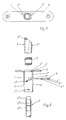
- Fig. 1 und Fig. 2 eine erste Ausführungsform des Schaltschlosses in der Türoffenstellung, und zwar in teilweise geschnittener Vorderansicht und in der Seitenansicht,
- Fig. 3 und Fig. 4 das gleiche Schaltschloß in gleichen Ansichten jedoch bei geschlossenem Türflügel,
- Fig. 5 die Draufsicht auf ein am Türrahmen anzubringendes Schließblech mit darunter sitzendem Schaltschloß,
- Fig. 6 eine Explosionsdarstellung des Schaltschlosses mit zugehörigem, teilweise dargestelltem Treibriegel,
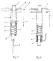
- Fig. 7 und 8 weitere Schaltschloß-Ausführungsformen und -Einbauweisen in jeweils senkrechtem Schnitt.
- 1 and Fig. 2 shows a first embodiment of the switch lock in the door open position, in a partially sectioned front view and in a side view,
- 3 and Fig. 4, the same switch lock in the same views but with the door leaf closed,
- 5 is a top view of a striking plate to be attached to the door frame with a key switch located underneath;
- 6 is an exploded view of the key switch with associated, partially shown drive bolt,
- 7 and 8 further switch lock embodiments and installation methods in a vertical section.
Das in den Fig. 1 bis 6 dargestellte Treibriegel-Schaltschloß ist in der oberen Ecke eines Türflügels 1 eingebaut, der mit einem Treibstangenverschluß etwa gemäß der DE-PS 27 46 049 versehen ist und von dem die den Treibriegel 2 bildende Treibstange lediglich strichpunktiert angedeutet ist. Das Schaltschloß besitzt ein mit dem Schloßstulp 3 verbundenes Schloßgehäuse 4, das hohlzylindrisch gestaltet ist. Das Schloßgehäuse 4 kann vorteilhaft aus entsprechend gerolltem Stahlblech bestehen, das mit dem z. B. aus Stanzblech bestehenden Stulp 3 verbunden, z. B. verschweißt, verlötet oder auch vernietet ist.1 to 6 drive latch switch lock is installed in the upper corner of a
Im zylindrischen Schloßgehäuse 4 sind die entsprechend zylindrisch gestaltete Schaltfalle 5, die im wesentlichen ringförmig gestaltete Klemmplatte 6 und die Klemmplatten-Druckfeder 7 untergebracht. Die Schaltfalle 5 ist mit einer in ihrer Verschieberichtung durchgehend verlaufenden Höhlung 5′ versehen, durch die der Treibriegel 2 hindurchzustecken ist bzw. die er in Einbaustellung axial verschieblich durchdringt. Somit wird der Riegel 2 von der Schaltfalle 5, der Klemmplatte 6 und auch der Druckfeder 7 sowie insgesamt auch von dem Schloßgehäuse 4 eng konzentrisch umhüllt, wodurch sich eine außerordentlich raumsparende Bauweise für das Schaltschloß ergibt.In the
Die ringförmige Klemmplatte 6 ist an ihrem Außenumfang mit Führungsnocken 6′ versehen, über die sie in im zylindrischen Schloßgehäuse 4 vorhandenen Längsschlitzen 4′ verdrehungssicher geführt ist. Die an ihr angreifende Schraubendruckfeder 7 stützt sich an ihrem unteren Ende an aus dem Schloßgehäuse 4 nach innen herausgebogenen Stützlappen 4˝ ab. Sie ist bestrebt, die Klemmplatte 6 über den abgewinkelten Führungsnocken 6′ in ihre in Fig. 1 dargestellte verkantete Sperrstellung zu drücken, in der sie mit ihrem den Treibriegel 2 umgreifenden Klemmauge 6˝ den Treibriegel in jeder beliebigen Einfahrstellung zu blockieren erlaubt. Dabei stützt sich die Klemmplatte 6 mit ihrem in Fig. 1 links dargestellten Führungsnocken 6‴ an dem am Schloßgehäuse 4 vorhandenen, den zugehörigen Längsschlitz 4′ begrenzenden Anschlag 4‴ ab.The
Die hohlzylindrisch gestaltete Schaltfalle 5 besteht vorteilhaft aus Spritzkunststoff, wenngleich sie grundsätzlich auch aus anderem Werkstoff, z. B. aus Druckguß, Feinguß oder Sintermetall bestehen kann. Um ihren Einbau in das Schloßgehäuse 4 so einfach wie möglich zu gestalten, ist sie mit einem seitlich angeordneten federnden Vorsprung 5˝ versehen, der beim Einsetzen der Schaltfalle 5 in das Schloßgehäuse 4 in den oberen Abschnitt 4IV des einen Längsschlitzes 4′ schnappartig einspringt und dadurch die Falle 5 sowohl verdrehungssicher im Schloßgehäuse 4 führt, als auch im Zusammenwirken mit dem vom federnden Vorsprung 5˝ hintergriffenen Anschlag 3′ am Schloßstulp 3 die Ausfahrbewegung der Schaltfalle 5 begrenzt. Im Schloßstulp 3 ist eine dem Innendurchmesser des Schloßgehäuses 4 im wesentlichen entsprechende Durchtrittsöffnung 3˝ für die Schaltfalle 5 und den sie durchsetzenden Treibriegel 2 vorhanden. Am äußeren mit einer entsprechenden Schrägfläche 5‴ versehenen Ende ist die Falle 5 mit beidseitig ausladenden Stützflügeln 5IV versehen. Sie verhindern, daß die Schaltfalle 5 in der in den Fig. 3 und 4 dargestellten Schließstellung des Türflügels 1 etwa auch in die Schließöffnung 8′ des am festen Rahmen 9 angeordneten Schließblechs 8 einfährt. Damit die Schaltfalle 5 bei z. B. enger Tür-Falzluft vollständig in den Schloßstulp 3 einfahren kann, ist die in letzterem vorhandene Durchtrittsöffnung 3˝ vorteilhaft so konturiert, daß sie dem Schaltfallen-Profil nebst den an der Schaltfalle vorhandenen Stützflügeln 5IV entspricht.The hollow
Der in Fig. 6 unten teilweise dargestellte Treibriegel besteht vorteilhaft aus Stahlrohr 2′, in dessen oberes, durch das Schaltschloß und dessen Klemmplatte 6 zu blockierendes Ende der vorzugsweise aus gehärtetem Stahl bestehende Bolzen 2˝ eingesteckt ist. Durch den am äußeren Ende vorhandenen Konus 2‴ wird das Einlaufen des Treibriegels in die Schließblechöffnung 8′ erleichtert.The driving bolt partially shown in Fig. 6 below advantageously consists of steel tube 2 ', in the upper end to be blocked by the switching lock and its
Die Fig. 6 veranschaulicht auch die einfache Montage der einzelnen Schaltschloßelemente. Zunächst wird die Druckfeder 7 in das Schloßgehäuse 4 eingelegt, wobei sie sich mit ihrem unteren Ende an den Stützlappen 4˝ abstützt. Sodann wird die Klemmplatte 6 durch den im Schloßgehäuse 4 vorhandenen, sich etwa über dessen halbe Breite erstreckenden Querschlitz 4V in der dargestellten Pfeilrichtung radial eingeschoben, bis der Führungsnocken 6‴ unter den Begrenzungsanschlag 4‴ gelangt. Danach wird dann die Schaltfalle 5 in das Schloßgehäuse 4 eingesteckt, und zwar so weit, bis sie mit ihrem federnden Vorsprung 5˝ hinter den am Schloßstulp 3 vorhandenen Anschlag 3′ einspringt, also auch in den oberen Teil 4IV des in Fig. 6 rechts vorhandenen Längsschlitzes 4′. In dieser Form kann das Schaltschloß in eine im Türflügel einfach anzubringende Bohrung eingesetzt und dann auch erst die Treibriegelstange 2 installiert werden. Durch die zylindrische Kompaktbauweise des Schaltschlosses, dessen Schloßgehäuse einen unter 19 mm liegenden Außendurchmesser besitzen kann, erfordert der Einbau dieses Schaltschlosses nur eine Bohrung mit einem Durchmesser von 20 mm. Ein weiterer wesentlicher Vorteil dieses engbauenden Treibriegel-Schaltschlosses besteht darin, daß seine Klemmplatte 6 nur geringe Rückfederungen der Treibriegelstange 2 zuläßt. Dadurch ist auch der zum Lösen der Klemmplatte notwendige Eindrückhub der Schaltfalle gegenüber der früheren Bauart wesentlich kürzer geworden. Das wiederum erlaubt es auch, auf die in der DE-PS 29 12 881 beschriebene Verstellbarkeit der Schaltfalle verzichten zu können, zumal der nutzbare Fallenhub auch dadurch vergrößert worden ist, daß die Klemmplatte bei der Einwärtsbewegung in Öffnungsrichtung gegen keinen Anschlag mehr trifft.6 also illustrates the simple assembly of the individual switch lock elements. First, the
Die Fig. 7 und 8 zeigen, wie das neue Schaltschloß auch zu einer eigenständigen Funktionseinheit erweitert, also mit einem eigenen integrierten Treibriegel 2 versehen werden kann. Dabei ist in beiden Fällen das Schloßgehäuse 4 innen mit einem koaxial zu ihm liegenden Gehäusefortsatz 10 versehen, in welchem die den Treibriegel 2 in seine dargestellte, ausgefahrene Verriegelungsstellung zu drücken suchende Feder 11 untergebracht ist, die mit ihrem oberen Ende an der Treibstange 2, beispielsweise an deren Knebel 12, angreift und mit ihrem anderen unteren Ende auf dem die Durchtrittsöffnung 10′ für den Treibriegel 2 begrenzenden Gehäuserand 10˝ abgestützt ist.7 and 8 show how the new key switch can also be expanded to an independent functional unit, that is to say can be provided with its own
Im Falle der Fig. 7 kann der Riegel 2 durch ein als Betätigungskraftangriff dienendes mechanisches Zugverbindungsmittel, z. B. einen Seil- oder Kettenzug 13 gegen die Wirkung seiner Feder 11 eingefahren werden, beispielsweise über eine am anderen nicht dargestellten Ende des Zugseils 13 angreifende Betätigungshandhabe, z. B. einen Drücker od. dgl..In the case of Fig. 7, the
Im Falle der Fig. 8 ist als Betätigungskraftangriff anstelle der manuellen Zugverbindung zur Freigabe des Türflügels ein den Treibriegel 2 umgreifender Elektromagnet 14 am Gehäusefortsatz 10 angebracht, der bei Stromdurchfluß seiner Spulenwicklung den Treibriegel 2 in seine den Türflügel 1 freigebende Einfahrstellung zu ziehen vermag. Im einen wie im anderen Falle kann der Gehäusefortsatz 10 einfach mit in die unteren Enden der Längsschlitze 4′ am Schloßgehäuse einschnappenden Haltebügeln od. dgl. befestigt sein. Es versteht sich aber, daß auch andere Verbindungsmöglichkeiten zwischen den beiden Gehäuseteilen möglich sind, insbesondere auch eine einteilige Ausbildung von Schloßgehäuse 4 und Fortsatz 10.In the case of FIG. 8, an
Im Rahmen der vorliegenden Erfindung sind mancherlei Abwandlungen möglich. Insbesondere versteht es sich auch, daß das neue Treibriegel-Schaltschloß nicht nur mit einem im Standflügel von zweiflügeligen Türen untergebrachten Treibstangenverschluß kombiniert zu werden braucht, sondern daß es ohne weiteres auch in einflügelige Türen oder auch in Schiebetüren und dgl. Türflügel einzubauen ist.Various modifications are possible within the scope of the present invention. In particular, it also goes without saying that the new drive bolt key switch not only needs to be combined with a drive rod lock housed in the passive leaf of double-leaf doors, but that it can also be easily installed in single-leaf doors or also in sliding doors and the like.
Claims (14)
- Driven bolt fastener, more particularly for espagnolettes for the wings of doors and the like, with a lock plate (3) having a through opening (3'') for the lock casing (4) having a driven bolt (2) sprung in the direction of its extended locking position, a sprung clamping plate (6) arranged therein which surrounds the driven bolt (2) with a clamping eye (6'') and allows it to be blocked in any insert position, as well as a latch (5) also penetrating through the lock plate (3) and sprung, which is pressed in on contacting the door frame and thereby moves the clamping plate (6) into its position for releasing the driven bolt (2), characterised in that the latch (5) is provided with a through cavity (5') running In the direction of movement, through which the driven bolt (2) is pushed.
- Driven bolt fastener according to claim 1, characterised in that the lock casing (4) and the latch (5) are of a hollow cylindrical design and together with the corresponding annular clamping plate (6) and a pressure spring (7) acting on them are arranged concentrically to the driven bolt (2) penetrating through the centre of all of them.
- Driven bolt fastener according to claim 2, characterised in that the latch (5) is in direct contact with the clamping plate (6) through its inner face end.
- Driven bolt fastener according to claim 2 characterised in that the annular clamping plate (6) is guided torsion-free in longitudinal slits (4') provided in the cylindrical lock casing (4) by means of guide cams (6', 6''') present on its external circumference.
- Driven bolt fastener according to one of claims 1 to 4, characterised in that the latch (5) is provided with laterally projecting support wings (5IV) on its outer mitred end.
- Driven bolt fastener according to claim 5, characterised in that the through opening (3'') in the lock plate has a contour corresponding to the latch profile and its support wings (5IV).
- Driven bolt fastener according to one of claims 1 to 6, characterised in that the latch (5) snaps into and is guided torsion-free in the lock casing (4) by means of a laterally arranged projection (5'') which engages in a longitudinal slit (4') of the lock casing (4) and is guided in a sprung manner therein.
- Driven bolt fastener according to claim 7, characterised in that the latch (5) is made of injection moulded plastic.
- Driven bolt fastener according to claim 2, characterised in that the pressure spring (7) acting on the clamping plate (6) is supported at its lower end on support tags (4'') bent out inwards from the lock casing (4).
- Driven bolt fastener according to one of claims 1 to 9, characterised in that the lock casing (4) is made of appropriately rolled steel which is connected with the lock plate (3).
- Driven bolt fastener according to one of claims 1 to 10, characterised in that the lock casing (4) is provided at the bottom with a casing extension (10) lying coaxially to it, in which the spring (11) endeavouring to push the driven bolt (2) into its closing position is arranged, and in that at the internal end of the driven bolt (2) penetrating the casing extension (10), there is an operating force acting against the driven bolt spring (11).
- Driven bolt fastener according to claim 11, characterised in that mechanical tension connection means (13 in fig. 7), e.g. a rope or chain pull acting on the end of the driven bolt serve as an operating force.
- Driven bolt fastener according to claim 11, characterised in that an electromagnet (14 in fig. 8) acting on the inner end of the driven bolt serves as an operating force.
- Driven bolt fastener according to one of claims 1 to 13, characterised in that the driven bolt (2) consists of steel tube (2') into the outer end of which a conically tapering steel bolt (2'' in fig. 6) is inserted.
Priority Applications (1)
| Application Number | Priority Date | Filing Date | Title |
|---|---|---|---|
| AT89111848T ATE86348T1 (en) | 1988-07-01 | 1989-06-29 | DRIVING BOLT SWITCH LOCK, PARTICULARLY FOR DRIVING ROD LOCKS ON DOOR DGL. |
Applications Claiming Priority (2)
| Application Number | Priority Date | Filing Date | Title |
|---|---|---|---|
| DE3822286A DE3822286A1 (en) | 1988-07-01 | 1988-07-01 | DRIVE LOCK SWITCH LOCK, ESPECIALLY FOR DRIVE ROD LOCKINGS ON DOOR-OD. DGL. -WING |
| DE3822286 | 1988-07-01 |
Publications (3)
| Publication Number | Publication Date |
|---|---|
| EP0348971A2 EP0348971A2 (en) | 1990-01-03 |
| EP0348971A3 EP0348971A3 (en) | 1990-09-05 |
| EP0348971B1 true EP0348971B1 (en) | 1993-03-03 |
Family
ID=6357749
Family Applications (1)
| Application Number | Title | Priority Date | Filing Date |
|---|---|---|---|
| EP89111848A Expired - Lifetime EP0348971B1 (en) | 1988-07-01 | 1989-06-29 | Fastener released upon closing a door, especially for an espagnolette for door wings or the like |
Country Status (3)
| Country | Link |
|---|---|
| EP (1) | EP0348971B1 (en) |
| AT (1) | ATE86348T1 (en) |
| DE (2) | DE3822286A1 (en) |
Cited By (5)
| Publication number | Priority date | Publication date | Assignee | Title |
|---|---|---|---|---|
| DE102009044654A1 (en) | 2009-11-25 | 2011-05-26 | Securidev S.A. | Pushrod switch lock |
| WO2016162195A1 (en) | 2015-04-10 | 2016-10-13 | Geze Gmbh | Switch lock |
| RU2804929C2 (en) * | 2021-12-14 | 2023-10-09 | Сергей Григорьевич Кузовников | Lock |
| US20240018805A1 (en) * | 2020-08-17 | 2024-01-18 | David Johannes MAC DONALD | Intermodal container door lock |
| DE102023112075A1 (en) * | 2023-05-09 | 2024-11-14 | Gretsch-Unitas GmbH Baubeschläge | latch arrangement and sash arrangement |
Families Citing this family (10)
| Publication number | Priority date | Publication date | Assignee | Title |
|---|---|---|---|---|
| DE8914367U1 (en) * | 1989-12-06 | 1991-04-04 | BKS GmbH, 5620 Velbert | Mortise lock with latch bolt |
| DE9104553U1 (en) * | 1991-04-13 | 1991-06-06 | BKS GmbH, 5620 Velbert | Multi-bolt door lock |
| DE9113493U1 (en) * | 1991-10-30 | 1992-01-16 | BKS GmbH, 5620 Velbert | Device for monitoring the locking engagement of espagnolette bars, in particular on espagnolette locks |
| ES2149062B1 (en) * | 1997-02-17 | 2001-04-16 | Talleres Escoriaza Sa | DEVICE OF HIGH OR LOW CLOSURE POINT, IN DOORS WITH AUTOMATIC LOCK. |
| DE19727365C1 (en) * | 1997-06-27 | 1998-10-22 | Schlechtendahl & Soehne Wilh | Locking pawl arrangement esp for spring-loaded bolt of fire-protection door |
| DE10118049C2 (en) * | 2001-04-11 | 2003-10-02 | Ist Systems Gmbh | Door opener with hinged latch |
| DE10318352B3 (en) | 2003-04-23 | 2004-10-14 | Wilka Schließtechnik GmbH | Switching lock for a door has clamping elements formed as clamping tappets guided in guiding grooves of a guiding sleeve |
| DE102006054745B4 (en) | 2006-11-21 | 2014-08-14 | Burg F.W. Lüling KG | Locking device for doors |
| DE202009004606U1 (en) * | 2009-04-03 | 2010-08-19 | Gebr. Bode Gmbh & Co. Kg | Electromagnetic door locking device |
| CN111282032B (en) * | 2020-02-13 | 2023-06-20 | 华中科技大学同济医学院附属协和医院 | A simple pinch trainer and its control method |
Family Cites Families (7)
| Publication number | Priority date | Publication date | Assignee | Title |
|---|---|---|---|---|
| GB612094A (en) * | 1946-10-04 | 1948-11-08 | Arthur W Adams Ltd | Improvements in or relating to panic bolts and like fastening devices for doors and other closure members |
| US2910857A (en) * | 1955-07-29 | 1959-11-03 | Kawanee Company | Emergency exit lock |
| DE6908036U (en) * | 1969-02-19 | 1969-06-19 | Willi Schmelter | MANSARD TIPPING WINDOWS |
| DE2746049C2 (en) * | 1977-10-13 | 1983-10-13 | Scovill Sicherheitseinrichtungen Gmbh, 5620 Velbert | Espagnolette lock on a door leaf |
| DE2912881A1 (en) * | 1979-03-30 | 1980-10-09 | Scovill Sicherheitseinrichtung | Two winged fire screen door drive bar lock - has auxiliary latch head axially adjustable on latch shaft |
| DE3535344A1 (en) * | 1985-10-03 | 1987-04-16 | Schlechtendahl & Soehne Wilh | Switching lock |
| DE8701630U1 (en) * | 1987-02-04 | 1987-05-14 | BKS GmbH, 5620 Velbert | Espagnolette lock for the passive leaf of double-leaf doors |
-
1988
- 1988-07-01 DE DE3822286A patent/DE3822286A1/en not_active Withdrawn
-
1989
- 1989-06-29 DE DE8989111848T patent/DE58903635D1/en not_active Expired - Lifetime
- 1989-06-29 EP EP89111848A patent/EP0348971B1/en not_active Expired - Lifetime
- 1989-06-29 AT AT89111848T patent/ATE86348T1/en not_active IP Right Cessation
Cited By (12)
| Publication number | Priority date | Publication date | Assignee | Title |
|---|---|---|---|---|
| DE102009044654A1 (en) | 2009-11-25 | 2011-05-26 | Securidev S.A. | Pushrod switch lock |
| EP2327851A2 (en) | 2009-11-25 | 2011-06-01 | Securidev S.A. | Lock with trigger actuated driving rod |
| EP2327851A3 (en) * | 2009-11-25 | 2016-04-27 | Securidev S.A. | Lock with trigger actuated driving rod |
| WO2016162195A1 (en) | 2015-04-10 | 2016-10-13 | Geze Gmbh | Switch lock |
| DE102015206417A1 (en) | 2015-04-10 | 2016-10-13 | Geze Gmbh | switch lock |
| CN107438690A (en) * | 2015-04-10 | 2017-12-05 | 盖慈有限公司 | Switch lock |
| EP3280853B1 (en) | 2015-04-10 | 2019-05-08 | GEZE GmbH | Switch lock |
| CN107438690B (en) * | 2015-04-10 | 2019-07-16 | 盖慈有限公司 | Switch lock |
| DE102015206417B4 (en) | 2015-04-10 | 2020-01-16 | Geze Gmbh | switch lock |
| US20240018805A1 (en) * | 2020-08-17 | 2024-01-18 | David Johannes MAC DONALD | Intermodal container door lock |
| RU2804929C2 (en) * | 2021-12-14 | 2023-10-09 | Сергей Григорьевич Кузовников | Lock |
| DE102023112075A1 (en) * | 2023-05-09 | 2024-11-14 | Gretsch-Unitas GmbH Baubeschläge | latch arrangement and sash arrangement |
Also Published As
| Publication number | Publication date |
|---|---|
| EP0348971A3 (en) | 1990-09-05 |
| DE3822286A1 (en) | 1990-01-04 |
| ATE86348T1 (en) | 1993-03-15 |
| DE58903635D1 (en) | 1993-04-08 |
| EP0348971A2 (en) | 1990-01-03 |
Similar Documents
| Publication | Publication Date | Title |
|---|---|---|
| DE69806907T3 (en) | CLOSING DEVICE FOR ONE DOOR | |
| EP0348971B1 (en) | Fastener released upon closing a door, especially for an espagnolette for door wings or the like | |
| EP0340750B1 (en) | Padlock | |
| EP2020474B1 (en) | Lock | |
| EP3884127B1 (en) | Door fitting having a handle which can be locked on one side | |
| DE3605826A1 (en) | Espagnolette fastening with handle return | |
| DE102011018658B4 (en) | Locking device of a folding backrest of a seat | |
| EP0260517B1 (en) | Handle, in particular window handle | |
| EP0635612B1 (en) | Doorlock device | |
| DE102011110636B4 (en) | Locking device and portable container equipped therewith | |
| AT403941B (en) | FITTING FOR A MOVABLE WING OF A WINDOW, DOOR OR THE LIKE. | |
| DE3636236A1 (en) | Panic fastening for two-wing doors | |
| CH697988B1 (en) | Switching mechanism in particular for espagnolette locks. | |
| EP3122968B1 (en) | Switch lock with tamper-proofing for preventing an auxiliary latch actuation | |
| EP0453626B1 (en) | Swivelling and submerging lever closure with lock device | |
| DE8816841U1 (en) | Drive bolt switch lock, especially for drive rod locks on doors or similar leaves | |
| DE69805942T2 (en) | Device for actuating a panic lock from the outside | |
| EP1920126A1 (en) | Actuation device for a lock | |
| WO2018082924A1 (en) | Locking unit for a motor vehicle | |
| DE3920361C2 (en) | ||
| DE3414642A1 (en) | Block lock | |
| DE60201616T2 (en) | Lock for door, window, etc. with rod-like fitting | |
| DE8312253U1 (en) | DEVICE FOR AUTOMATIC MISTAKE PROTECTION OF A ON A WINDOW OR THE LIKE. -WING PROVIDED ROD | |
| EP0550412A2 (en) | Padlock | |
| EP1790798A2 (en) | Lock cylinder, especially a profile cylinder, for a locking device such as a door lock |
Legal Events
| Date | Code | Title | Description |
|---|---|---|---|
| PUAI | Public reference made under article 153(3) epc to a published international application that has entered the european phase |
Free format text: ORIGINAL CODE: 0009012 |
|
| AK | Designated contracting states |
Kind code of ref document: A2 Designated state(s): AT BE CH DE FR GB IT LI NL SE |
|
| PUAL | Search report despatched |
Free format text: ORIGINAL CODE: 0009013 |
|
| AK | Designated contracting states |
Kind code of ref document: A3 Designated state(s): AT BE CH DE FR GB IT LI NL SE |
|
| 17P | Request for examination filed |
Effective date: 19900731 |
|
| 17Q | First examination report despatched |
Effective date: 19920604 |
|
| GRAA | (expected) grant |
Free format text: ORIGINAL CODE: 0009210 |
|
| AK | Designated contracting states |
Kind code of ref document: B1 Designated state(s): AT BE CH DE FR GB IT LI NL SE |
|
| REF | Corresponds to: |
Ref document number: 86348 Country of ref document: AT Date of ref document: 19930315 Kind code of ref document: T |
|
| GBT | Gb: translation of ep patent filed (gb section 77(6)(a)/1977) |
Effective date: 19930308 |
|
| REF | Corresponds to: |
Ref document number: 58903635 Country of ref document: DE Date of ref document: 19930408 |
|
| ITF | It: translation for a ep patent filed | ||
| ET | Fr: translation filed | ||
| PLBE | No opposition filed within time limit |
Free format text: ORIGINAL CODE: 0009261 |
|
| STAA | Information on the status of an ep patent application or granted ep patent |
Free format text: STATUS: NO OPPOSITION FILED WITHIN TIME LIMIT |
|
| 26N | No opposition filed | ||
| EAL | Se: european patent in force in sweden |
Ref document number: 89111848.1 |
|
| REG | Reference to a national code |
Ref country code: GB Ref legal event code: IF02 |
|
| REG | Reference to a national code |
Ref country code: CH Ref legal event code: PFA Owner name: BKS GMBH Free format text: BKS GMBH#HEIDESTRASSE 71#D-42549 VELBERT (DE) -TRANSFER TO- BKS GMBH#HEIDESTRASSE 71#D-42549 VELBERT (DE) |
|
| PGFP | Annual fee paid to national office [announced via postgrant information from national office to epo] |
Ref country code: CH Payment date: 20080613 Year of fee payment: 20 |
|
| PGFP | Annual fee paid to national office [announced via postgrant information from national office to epo] |
Ref country code: AT Payment date: 20080616 Year of fee payment: 20 |
|
| PGFP | Annual fee paid to national office [announced via postgrant information from national office to epo] |
Ref country code: IT Payment date: 20080625 Year of fee payment: 20 |
|
| PGFP | Annual fee paid to national office [announced via postgrant information from national office to epo] |
Ref country code: NL Payment date: 20080618 Year of fee payment: 20 Ref country code: DE Payment date: 20080829 Year of fee payment: 20 Ref country code: SE Payment date: 20080612 Year of fee payment: 20 |
|
| PGFP | Annual fee paid to national office [announced via postgrant information from national office to epo] |
Ref country code: FR Payment date: 20080613 Year of fee payment: 20 |
|
| PGFP | Annual fee paid to national office [announced via postgrant information from national office to epo] |
Ref country code: GB Payment date: 20080620 Year of fee payment: 20 |
|
| PGFP | Annual fee paid to national office [announced via postgrant information from national office to epo] |
Ref country code: BE Payment date: 20080728 Year of fee payment: 20 |
|
| BE20 | Be: patent expired |
Owner name: *BKS G.M.B.H. Effective date: 20090629 |
|
| REG | Reference to a national code |
Ref country code: CH Ref legal event code: PL |
|
| REG | Reference to a national code |
Ref country code: GB Ref legal event code: PE20 Expiry date: 20090628 |
|
| PG25 | Lapsed in a contracting state [announced via postgrant information from national office to epo] |
Ref country code: NL Free format text: LAPSE BECAUSE OF EXPIRATION OF PROTECTION Effective date: 20090629 |
|
| EUG | Se: european patent has lapsed | ||
| NLV7 | Nl: ceased due to reaching the maximum lifetime of a patent |
Effective date: 20090629 |
|
| PG25 | Lapsed in a contracting state [announced via postgrant information from national office to epo] |
Ref country code: GB Free format text: LAPSE BECAUSE OF EXPIRATION OF PROTECTION Effective date: 20090628 |