EP0343530A2 - Installation sous vide - Google Patents
Installation sous vide Download PDFInfo
- Publication number
- EP0343530A2 EP0343530A2 EP89109054A EP89109054A EP0343530A2 EP 0343530 A2 EP0343530 A2 EP 0343530A2 EP 89109054 A EP89109054 A EP 89109054A EP 89109054 A EP89109054 A EP 89109054A EP 0343530 A2 EP0343530 A2 EP 0343530A2
- Authority
- EP
- European Patent Office
- Prior art keywords
- chamber
- workpiece
- chambers
- vacuum system
- intermediate chamber
- Prior art date
- Legal status (The legal status is an assumption and is not a legal conclusion. Google has not performed a legal analysis and makes no representation as to the accuracy of the status listed.)
- Granted
Links
Images


Classifications
-
- H—ELECTRICITY
- H10—SEMICONDUCTOR DEVICES; ELECTRIC SOLID-STATE DEVICES NOT OTHERWISE PROVIDED FOR
- H10P—GENERIC PROCESSES OR APPARATUS FOR THE MANUFACTURE OR TREATMENT OF DEVICES COVERED BY CLASS H10
- H10P72/00—Handling or holding of wafers, substrates or devices during manufacture or treatment thereof
- H10P72/04—Apparatus for manufacture or treatment
- H10P72/0451—Apparatus for manufacturing or treating in a plurality of work-stations
- H10P72/0452—Apparatus for manufacturing or treating in a plurality of work-stations characterised by the layout of the process chambers
- H10P72/0454—Apparatus for manufacturing or treating in a plurality of work-stations characterised by the layout of the process chambers surrounding a central transfer chamber
-
- H—ELECTRICITY
- H10—SEMICONDUCTOR DEVICES; ELECTRIC SOLID-STATE DEVICES NOT OTHERWISE PROVIDED FOR
- H10P—GENERIC PROCESSES OR APPARATUS FOR THE MANUFACTURE OR TREATMENT OF DEVICES COVERED BY CLASS H10
- H10P72/00—Handling or holding of wafers, substrates or devices during manufacture or treatment thereof
- H10P72/04—Apparatus for manufacture or treatment
- H10P72/0451—Apparatus for manufacturing or treating in a plurality of work-stations
- H10P72/0462—Apparatus for manufacturing or treating in a plurality of work-stations characterised by the construction of the processing chambers, e.g. modular processing chambers
-
- H—ELECTRICITY
- H10—SEMICONDUCTOR DEVICES; ELECTRIC SOLID-STATE DEVICES NOT OTHERWISE PROVIDED FOR
- H10P—GENERIC PROCESSES OR APPARATUS FOR THE MANUFACTURE OR TREATMENT OF DEVICES COVERED BY CLASS H10
- H10P72/00—Handling or holding of wafers, substrates or devices during manufacture or treatment thereof
- H10P72/70—Handling or holding of wafers, substrates or devices during manufacture or treatment thereof for supporting or gripping
- H10P72/76—Handling or holding of wafers, substrates or devices during manufacture or treatment thereof for supporting or gripping using mechanical means, e.g. clamps or pinches
- H10P72/7602—Handling or holding of wafers, substrates or devices during manufacture or treatment thereof for supporting or gripping using mechanical means, e.g. clamps or pinches the wafers being placed on a robot blade or gripped by a gripper for conveyance
-
- Y—GENERAL TAGGING OF NEW TECHNOLOGICAL DEVELOPMENTS; GENERAL TAGGING OF CROSS-SECTIONAL TECHNOLOGIES SPANNING OVER SEVERAL SECTIONS OF THE IPC; TECHNICAL SUBJECTS COVERED BY FORMER USPC CROSS-REFERENCE ART COLLECTIONS [XRACs] AND DIGESTS
- Y10—TECHNICAL SUBJECTS COVERED BY FORMER USPC
- Y10S—TECHNICAL SUBJECTS COVERED BY FORMER USPC CROSS-REFERENCE ART COLLECTIONS [XRACs] AND DIGESTS
- Y10S414/00—Material or article handling
- Y10S414/135—Associated with semiconductor wafer handling
- Y10S414/137—Associated with semiconductor wafer handling including means for charging or discharging wafer cassette
-
- Y—GENERAL TAGGING OF NEW TECHNOLOGICAL DEVELOPMENTS; GENERAL TAGGING OF CROSS-SECTIONAL TECHNOLOGIES SPANNING OVER SEVERAL SECTIONS OF THE IPC; TECHNICAL SUBJECTS COVERED BY FORMER USPC CROSS-REFERENCE ART COLLECTIONS [XRACs] AND DIGESTS
- Y10—TECHNICAL SUBJECTS COVERED BY FORMER USPC
- Y10S—TECHNICAL SUBJECTS COVERED BY FORMER USPC CROSS-REFERENCE ART COLLECTIONS [XRACs] AND DIGESTS
- Y10S414/00—Material or article handling
- Y10S414/135—Associated with semiconductor wafer handling
- Y10S414/139—Associated with semiconductor wafer handling including wafer charging or discharging means for vacuum chamber
Definitions
- the present invention relates to a vacuum system for treating workpieces, with at least one process chamber for the workpieces and a central evacuable distributor chamber, into which the workpieces are introduced via locks by means of a first transport mechanism and then removed again after treatment.
- Such a multi-chamber system for the treatment of silicon wafers is known from the magazine Solid State Technology / October 1987 (pages 55/56), which has a robot arm in a central distributor chamber which feeds the individual semiconductor wafers to be treated to the individual process chambers in accordance with a predetermined program after removal of a process, for example a coating, takes it out of it again.
- a plurality of process chambers can be connected to such a central distributor chamber, the semiconductor wafers being able to be conveyed through the distributor chamber from one process chamber to the other without having to be transferred into the free atmosphere between the individual processes.
- the present invention is based on the object of providing a vacuum system with a plurality of process chambers, in which the aforementioned risk of carryover of residual gases and particles from one process chamber to another or from one workpiece to another is reduced to a minimum or is eliminated at all is.
- the vacuum system has the features of claim 1.
- several intermediate chambers with associated process chambers can be connected to the distribution chamber and / or several process chambers can be assigned to an intermediate chamber.
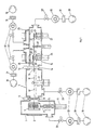
- FIG. 1 shows the lock chamber with a gate 2 to the free atmosphere and with a holder 3 arranged in the chamber for a wafer magazine 4.
- This can be raised and lowered by means of a lifting device provided with a bellows seal 5 and an actuating device 6 such that in each case a specific pane to be treated the magazine 4 is at a suitable height for insertion into the distribution chamber 7 through the opening of the valve 8; the latter is opened or closed as required by an actuator 9.
- a first mechanism 10, 11 is provided for conveying the disk removed from the magazine to the intermediate chamber 15.
- This distributor mechanism has a rotatably arranged robot arm 10, to which a controllable drive device 11 is assigned.
- the robot arm 10 takes a disk from the magazine 4 by means of the disk support 12 when the valve 8 is open and brings it through the opened valve 14 which can be actuated by the auxiliary device 13 into the intermediate chamber 15. If there are several intermediate chambers, the Washer introduced into the intermediate chamber corresponding to the process program.
- Fig. 1 the position of the rotatable robot arm 10, in which it takes over the disc from the magazine 4, with 10 'dash-dotted line, on the other hand, the position in which he passes this with the valve 14 open to the intermediate chamber 15, with 10 in full Lines drawn.
- a second mechanism for handling the discs is housed in the intermediate chamber 15, from which the disks are passed on to the individual connected process chambers 24 and 25, in which they process certain steps, e.g. a coating or etching in the course of a manufacturing process.
- this second mechanism is designed as a rotating arm 20 with grippers 21 for taking over the disks brought by the first mechanism.
- the grippers 21 By correspondingly rotating the grippers 21 along a circular path, the disks can be brought under the openings 22 and 23 located on a circle to the process chambers 24 and 25 and from there by means of lifting devices 26 and 27 (which can be equipped similarly to that in the lock chamber 1) are lifted up into the treatment positions of the individual process chambers or lowered again after a treatment has been carried out and conveyed on to another process station.
- the lifting devices are also equipped with ring seals 28 and 29 which, when fitted to the ceiling of the intermediate chambers around the openings 22 and 23, result in a vacuum-tight shut-off between the intermediate chamber and the process chambers;
- the closed position of the seal 28 is indicated with 28 '.
- FIG. 1 also shows schematically the pumping stations assigned to the various chambers, of which each can consist, for example, of a backing pump 30, a condenser 31, a high vacuum pump 32 and a valve 33. All valves and the pumps can be connected to a control mechanism or a control computer in order to actuate them in accordance with a desired process sequence (which does not form the subject of the present invention).
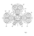
- the reference numeral 40 designates the central distribution chamber into which the panes to be treated can be introduced via lock chambers 42 and can be removed again after the treatment.
- the intermediate chambers 44, 44 'and 44 ⁇ are connected on three sides and each of these intermediate chambers are assigned three process chambers in the exemplary embodiment, which are shown schematically in FIG. 2 with 45, 46 and 47 or 45', 46 ' 47 'and 45 ⁇ , 46 ⁇ and 47 ⁇ are designated.
- the connection between the distribution chamber and the connected intermediate chambers is given by the valves 48 or 48 'or 48', which are opened and closed accordingly by a control device for the processes to be carried out.
- first and second mechanisms are accommodated in the central distributor chamber or in the intermediate chambers flanged to them; they provide process-oriented transport of the disks in and out of the individual chambers, similar to that described with reference to the example in FIG. 1.
- Fig. 3 shows the first and second mechanisms used in the embodiment of Fig. 1 and the interaction of the two. Where used, the reference numerals are the same as in FIG. 1.
- a plate is fastened to the robot arm 10 controlled by the drive device 11, which plate engages under the disks and takes them over from the cassette in the lock chamber and then after retraction and rotation of the Robot arms from the position 10 'in the position 10 (see Fig. 1) to the gripper 21 in the chamber 15.
- the second mechanism the disks are then brought into the correct position relative to the opening of a process chamber by rotating about the axis 20 '.
- the device according to FIG. 11 is designed in such a way that the disk in question is already in this position opposite the process chamber 24 after transfer to the second mechanism.
- the method according to the invention for operating the vacuum system is explained with reference to FIG. 1 and is characterized in that the first transport mechanism 10, 11, 12 arranged in the distribution chamber 7 successively removes and opens a workpiece from a magazine 4 in the lock 1 transported through the distribution chamber 7 into an intermediate chamber 15 and the second transport mechanism 20, 21 arranged in the intermediate chamber takes over the workpiece from the first transport mechanism 10, 11, 12 and in one to the connection opening holds 22 or 23 between the intermediate chamber 15 and a process chamber 24 or 25 coaxial position.
- this operating method in the presence of a plurality of process chambers 24, 25 assigned to an intermediate chamber 15 and below the connecting openings 22, 23 between the latter and the intermediate chamber 15 arranged in this lifting devices 26, 27 for the up and down transport of the panes into and out of the process chambers characterized in that the second transport mechanism 20, 21 deposits the workpiece taken over from the first transport mechanism 10, 11, 12 on one of the lifting devices 26, 27, which transports the workpiece into one of the process chambers 24, 25 located above the lifting devices, and that the workpiece is transported back to the starting position in the same way with the reverse order of the transport steps.
- the method for operating the vacuum system can in particular be designed in such a way that, in the presence of at least two process chambers 24, 25 each assigned to an intermediate chamber 15, each of these process chambers is activated and regenerated alternately after loading during successive time intervals, the process chamber being regenerated another chamber is put into operation.
- a certain period of time during which a disk is treated in this chamber is followed by a period of time during which this chamber is regenerated.
- this can be carried out alternately, so that the regeneration phase and the treatment phase are constantly exchanged.
- the method for operating the vacuum system can also be designed according to the invention in such a way that a magazine with a supply instead of a lifting device 26 or 27 is placed in an intermediate chamber 15 Disks is arranged and that an intermediate chamber with several, for example, three of these assigned process chambers is then put into operation as a unit that is functional independently of the rest of the vacuum system and, in other words, can work autonomously if, for example, the other parts of the vacuum system fail due to a malfunction.
- the vacuum system in each existing intermediate chamber has lifting devices which serve to bring a disc placed on the lifting device into a process chamber arranged above the intermediate chamber.
- the disk-shaped workpiece must be secured on the base of the lifting device, i.e. the workpiece must be held on the edge so that it maintains a certain position.
- gripper-like leaf springs for holding the workpiece, for example in the form of a disk, which encompass the disk edge.
- These holding means can be brought into an open and a closed position in which they hold the disc.
- This treatment is, for example, a coating with 1
- the treatment is an aez process
- the Festhal also etched and the material removed from them can contaminate the pane surface.
- the holding means also cause potential distortions and, as a result, often a kind of courtyard or shadow.
- the pane to be treated should also be positioned with a certain orientation of its position on the base of the lifting device before the pane is transported into the process chamber.
- the wafer has, for example, a contour that deviates from the circular shape, with a circular segment being cut away, which serves to identify the crystal orientation, and the base for the wafer has the same contour that deviates from the circular shape and the pane must be held and transported precisely in relation to this base.
- a lifting device in the form of a special lifting table with holding means is required, which is able to bring the workpiece into an oriented position on the base and to secure the workpiece during transport without it itself are exposed to the effects of this treatment during the treatment of the workpiece.
- the lifting table to be used in the vacuum system should also make it possible for the workpiece to be treated in the process chamber at certain temperatures which are to be kept exactly constant. This may require the application of heat against the underside of the workpiece or cooling.
- the workpiece support is equipped with a heating plate which can be heated by a heating element and with a large number of channels opening onto the surface of the support, which are jointly connected to a gas supply line, in order to provide a gas cushion between the support and the workpiece as a homogeneous one To generate heat conduction for heating the workpiece.
- the gas cushion ensures an absolutely even heat distribution underneath the workpiece. So that the workpiece does not stand out from the base due to the gas cushion, a loose ring serves as the weight load, which comes to rest on the outer edge of the workpiece in the processing station. This ring also has the task of keeping the existing annular gap between the support carrying the workpiece and the cover closed.
- a ring can of course also be used for this purpose, which only rests on the edge of the base but not on the edge of the workpiece, so that it can also be transported exposed. This makes it possible to process either an exposed or an edge-secured workpiece with the same device, depending on what type of processing is currently required.
- the ring preferably lies along the entire edge of the workpiece, if a sealing effect for the gas cushion between the workpiece and the base is to be achieved.
- the ring can be attached in a gas-tight manner to the housing of the vacuum system by means of a bellows, wherein the spring action of the bellows can also be used to counteract the pressure of the gas cushion. If, on the other hand, the workpiece is to be treated to the extreme edge, the ring can also rest on the workpiece edge with hooks arranged on the inner edge, so that the majority of the workpiece edge is machined in addition to these hook areas.
- the lifting table with the holding members pivotably arranged in and out of holding engagement has the advantage that the holding members protected behind the cover in the out of holding engagement position cannot stick to the workpiece due to the effects of the treatment.
- the pivotable holding members in their position pivoted inward against the workpiece, fulfill the function of separating the workpiece from the ring by tearing when the lifting table returns to the starting position.
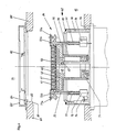
- FIG. 4 shows the essential parts of one of the lifting devices 26 and 27 shown in FIG. 1, which are each designed as a lifting table for moving a workpiece up and down within the intermediate chamber 15.
- the lifting table 26 is shown in FIG. 4 in the so-called loading position, in which a disk-shaped workpiece 61 is placed on the workpiece support 62 consisting of several parts, specifically on the central part 63, which in the example shown is equipped with a heating plate 64 which is heated by a heating element 65 and which heating plate is provided with a plurality of vertical bores 66 through which a gas passes between the disc-shaped Workpiece 61 and the top of the heating plate 64 can reach.
- the heating element 65 can heat the heating plate 64 to temperatures above 500 ° C.
- the heated gas then serves as a heat conduction means in order to heat the workpiece completely uniformly over its surface.
- the same gas is preferably used, which is also used in a process carried out in the vacuum system, because a gas-tight seal at the edge of the heating plate is very difficult to achieve.
- a flange 67 located below the heating plate 64 serves for fastening the heating element 65 and for supplying gas to the bores 66 in the heating plate.
- This heating plate and the flange 67 are fastened together on a further flange 68, which contains channels 69 of a rapid cooling device.
- the flange 68 is connected in a heat-insulating manner by means of a thin-walled tube 70 to a part 71, which is also cooled and is electrically insulated, and is connected in a gas-tight manner.
- the workpiece support 62 which can be moved up and down, also includes holding members 72 and 73 which can be pivoted about it. From FIG. 7 it can be seen that two of these holding members 72 are present on one side and a holding member 73 is present on the opposite side. After the workpiece 61 has been placed on the support 62, the holding members are pivoted from a position 72a or 73a, in which they are not in engagement with the workpiece, to the position 72b or 73b, in which they are in engagement. For this purpose, they are pivoted about an axis 74 parallel to the central axis of the workpiece support 62. If necessary, this movement also corrects the position of the workpiece 62 on the support, which will be explained in more detail later with reference to FIG. 7.
- the holding members 72 and 73 each consist of a rod-shaped body 75 which is in a bearing 76 about its axis is rotatably mounted. Each holding element can be pressed down against the action of a compression spring 77 supported on the bearing and surrounding the rod-shaped body 15.
- the workpiece support 62 which can be moved up and down, also includes a cylindrical outer part 78, within which the holding members 72 and 73 are arranged so as to be pivotable.
- the lifting table 26 extends from below through a recess in the chamber wall 79 of the intermediate chamber 15, the lifting table being flanged against this wall 79 on the underside. 1 and 4 there is a process chamber 24 above the intermediate chamber 15, which are connected to one another via a connecting opening 22 in the wall 80 located between them.
- the upper edge of the cylindrical outer part 78 comes into sealing contact with a seal 82 against a region formed on this wall 80 at the edge of the opening 22 as the lift table 26 is raised in order to treat a workpiece 61 within the process chamber 24.
- the lifting table 26 thus serves not only for the up and down transport of the workpieces, but also represents a valve which separates the intermediate chamber 15 from the process chamber in a gas-tight manner.
- an annular cover 83 located within the process chamber 24 is fastened to the chamber wall 80.
- a loose ring 84 rests on the edge of the chamber wall and is guided in the opening 22.
- this ring 84 has hooks 85 arranged distributed around the circumference.
- the workpiece support 62 is shown raised to an intermediate station.
- the workpiece 61 lying on the base has slightly raised the loose ring 84 and the ring hangs with its hooks 85 on the edge of the workpiece, so that the latter is against the heating plate 64 is pressed and secured against slipping sideways.
- the ring also serves as a weight load to counteract the aforementioned gas cushion between the workpiece and the heating plate.
- the ring 84 has the task of covering the annular gap present between the cover 83 and the workpiece which has been raised on the base, in order to protect the parts underneath from the effects of the treatment taking place in the process chamber.
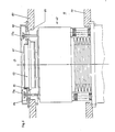
- the holding members 72 and 73 are shown in Fig. 5 in the position out of holding engagement, ie pivoted outwards.
- Fig. 6 the workpiece support 62 is shown raised to the end position and is in the processing position. This position is reached when the cylindrical outer part 78 of the base 62 is moved against the edge of the chamber wall 80 which is designed as a valve seat 81. The workpiece 61 then projects beyond the cover 83 and is fully exposed to the treatment in the process chamber 24.
- the holding members 72 and 73 are pressed against the cover 83 on the underside, wherein they are pushed inward against the action of the spring 77. In this position, below the cover 83, the holding members 72 and 73 are protected from the effects of the workpiece treatment.
- FIG. 6 shows different embodiments on the left and on the right half, and the movable ring 84 can only be seen in the left half.
- an annular shield 86 is shown which is fastened to the base 62 and which covers the annular gap between the cover 83 and the workpiece in order to protect the parts underneath from the effects of the process chamber.
- This shielding in the form of a channel has to absorb gradually build-up of coverings during coating processes, for example an aluminum up to 7mm thick nium layer. Such layers can also grow on the cover 83, which is why this cover can be easily replaced from the process chamber 24, which also applies to the loose ring 84 and the shield 86.
- the right half of FIG. 6 shows the possible design only with a workpiece support plate, ie without a heating plate
- FIG. 7 shows the loose ring 84 with the hook 85 arranged on the inner edge in a top view from above, as well as the holding members 72 and 73 in cooperation with the disk-shaped workpiece 61 shown in broken lines.
- the viewing direction is from the process chamber 24, when the cover 83 is removed.
- FIG. 7 shows the situation after reaching the workpiece support 62 in the intermediate position according to FIG. 5, but before the holding members 72 and 73 swivel outward.
- the representation according to FIG. 7 is in other words identical to the situation in the loading position according to FIG 4 after the holding members have been pivoted inward, if one imagines the loose ring 84 lying in a plane above the workpiece 61 and the holding members in FIG.
- the two aforementioned situations are repeated when the workpiece is returned from the machining position to the loading position.
- the workpiece orientation is corrected twice in each machining cycle with back and forth transport, namely when the holding members 72 and 73 are pivoted inward into the position shown in FIG.
- the two holding members 72 are pivoted about axes 87 parallel to the central axis, which are not shown in FIG. 4, and pressed hard against a mechanical stop.
- the holding member 73 is pivoted inward about the axis 74 also shown in FIG. 4.
- the holding member presses the workpiece 61 with the segment edge 6la (or flat) against the two holding members 72 and thereby corrects the Workpiece orientation if the holding members 72 are not simultaneously touched by the segment edge 61a, ie if the holding members 72 and this edge 6la were not parallel from the start.
- a displacement of the workpiece in the direction of the axis 88 by the process of the orientation correction can be limited in both positions, namely in the loading position by the means not described here for the workpiece transport from one station to another and in the intermediate station through the loose ring 84 or thereon fastened parts.
Landscapes
- Container, Conveyance, Adherence, Positioning, Of Wafer (AREA)
- Coating Apparatus (AREA)
- Physical Vapour Deposition (AREA)
- Drying Of Semiconductors (AREA)
- Manipulator (AREA)
- Fluid-Driven Valves (AREA)
- Electron Tubes For Measurement (AREA)
- Applications Or Details Of Rotary Compressors (AREA)
Applications Claiming Priority (6)
| Application Number | Priority Date | Filing Date | Title |
|---|---|---|---|
| CH195188 | 1988-05-24 | ||
| CH1951/88 | 1988-05-24 | ||
| CH195188 | 1988-05-24 | ||
| CH272288 | 1988-07-15 | ||
| CH2722/88 | 1988-07-15 | ||
| CH272288 | 1988-07-15 |
Publications (3)
| Publication Number | Publication Date |
|---|---|
| EP0343530A2 true EP0343530A2 (fr) | 1989-11-29 |
| EP0343530A3 EP0343530A3 (fr) | 1990-12-27 |
| EP0343530B1 EP0343530B1 (fr) | 2001-11-14 |
Family
ID=25689081
Family Applications (1)
| Application Number | Title | Priority Date | Filing Date |
|---|---|---|---|
| EP89109054A Expired - Lifetime EP0343530B1 (fr) | 1988-05-24 | 1989-05-19 | Installation sous vide |
Country Status (6)
| Country | Link |
|---|---|
| US (2) | US4990047A (fr) |
| EP (1) | EP0343530B1 (fr) |
| JP (4) | JP3121602B2 (fr) |
| AT (1) | ATE208961T1 (fr) |
| DE (1) | DE58909880D1 (fr) |
| ES (1) | ES2163388T3 (fr) |
Cited By (3)
| Publication number | Priority date | Publication date | Assignee | Title |
|---|---|---|---|---|
| DE4235674A1 (de) * | 1992-10-22 | 1994-04-28 | Balzers Hochvakuum | Kammer für den Transport von Werkstücken in Vakuumatmosphäre, Kammerkombination und Verfahren zum Transportieren eines Werkstückes |
| EP0452939B1 (fr) * | 1990-04-19 | 2000-11-02 | Applied Materials, Inc. | Appareil et méthode pour charger des pièces dans un système de traitement |
| RU2700872C1 (ru) * | 2018-08-23 | 2019-09-23 | Акционерное общество "Объединенная двигателестроительная корпорация" (АО "ОДК") | Вакуумная установка пиролиза |
Families Citing this family (101)
| Publication number | Priority date | Publication date | Assignee | Title |
|---|---|---|---|---|
| US5228501A (en) * | 1986-12-19 | 1993-07-20 | Applied Materials, Inc. | Physical vapor deposition clamping mechanism and heater/cooler |
| US5484011A (en) * | 1986-12-19 | 1996-01-16 | Applied Materials, Inc. | Method of heating and cooling a wafer during semiconductor processing |
| EP0350752B1 (fr) * | 1988-07-15 | 1993-10-13 | Balzers Aktiengesellschaft | Dispositif de support pour un disque ainsi que son application |
| US5098245A (en) * | 1989-02-24 | 1992-03-24 | U.S. Philips Corporation | High speed wafer handler |
| DE3915038A1 (de) * | 1989-05-08 | 1990-11-22 | Balzers Hochvakuum | Halte- und transportvorrichtung fuer eine scheibe |
| US5094885A (en) * | 1990-10-12 | 1992-03-10 | Genus, Inc. | Differential pressure cvd chuck |
| JPH0419081A (ja) * | 1990-05-15 | 1992-01-23 | Seiko Instr Inc | 真空内搬送ロボット |
| EP0468409B1 (fr) * | 1990-07-23 | 1995-10-04 | Dainippon Screen Mfg. Co., Ltd. | Appareil interface pour transporter des substrats entre des appareils de traitement |
| JPH081923B2 (ja) * | 1991-06-24 | 1996-01-10 | ティーディーケイ株式会社 | クリーン搬送方法及び装置 |
| JP3030667B2 (ja) * | 1991-07-29 | 2000-04-10 | 東京エレクトロン株式会社 | 搬送装置 |
| JP3238432B2 (ja) * | 1991-08-27 | 2001-12-17 | 東芝機械株式会社 | マルチチャンバ型枚葉処理装置 |
| US5658115A (en) * | 1991-09-05 | 1997-08-19 | Hitachi, Ltd. | Transfer apparatus |
| JP2598353B2 (ja) * | 1991-12-04 | 1997-04-09 | アネルバ株式会社 | 基板処理装置、基板搬送装置及び基板交換方法 |
| JPH0552808U (ja) * | 1991-12-24 | 1993-07-13 | 富士写真光機株式会社 | プロジェクタの投影レンズ |
| JPH05218176A (ja) * | 1992-02-07 | 1993-08-27 | Tokyo Electron Tohoku Kk | 熱処理方法及び被処理体の移載方法 |
| US5404894A (en) * | 1992-05-20 | 1995-04-11 | Tokyo Electron Kabushiki Kaisha | Conveyor apparatus |
| JPH0616206A (ja) * | 1992-07-03 | 1994-01-25 | Shinko Electric Co Ltd | クリーンルーム内搬送システム |
| US5697749A (en) * | 1992-07-17 | 1997-12-16 | Tokyo Electron Kabushiki Kaisha | Wafer processing apparatus |
| KR100302012B1 (ko) * | 1992-11-06 | 2001-11-30 | 조셉 제이. 스위니 | 미소-환경 콘테이너 연결방법 및 미소-환경 로드 로크 |
| KR100303075B1 (ko) | 1992-11-06 | 2001-11-30 | 조셉 제이. 스위니 | 집적회로 웨이퍼 이송 방법 및 장치 |
| US6136168A (en) * | 1993-01-21 | 2000-10-24 | Tdk Corporation | Clean transfer method and apparatus therefor |
| US5352294A (en) * | 1993-01-28 | 1994-10-04 | White John M | Alignment of a shadow frame and large flat substrates on a support |
| JP3218488B2 (ja) * | 1993-03-16 | 2001-10-15 | 東京エレクトロン株式会社 | 処理装置 |
| KR960009975B1 (ko) * | 1993-04-26 | 1996-07-25 | 한국베리안 주식회사 | 제2공간을 이용한 박막의 열처리 장치 |
| US5538390A (en) * | 1993-10-29 | 1996-07-23 | Applied Materials, Inc. | Enclosure for load lock interface |
| US5447431A (en) * | 1993-10-29 | 1995-09-05 | Brooks Automation, Inc. | Low-gas temperature stabilization system |
| US5588827A (en) * | 1993-12-17 | 1996-12-31 | Brooks Automation Inc. | Passive gas substrate thermal conditioning apparatus and method |
| EP0733130A4 (fr) * | 1993-12-17 | 1997-04-02 | Brooks Automation Inc | Appareil de chauffage ou de refroidissement de pastilles |
| US5791895A (en) * | 1994-02-17 | 1998-08-11 | Novellus Systems, Inc. | Apparatus for thermal treatment of thin film wafer |
| DE9407482U1 (de) * | 1994-05-05 | 1994-10-06 | Balzers und Leybold Deutschland Holding AG, 63450 Hanau | Funktionseinrichtung für eine Vakuumanlage für die Behandlung von scheibenförmigen Werkstücken |
| US5476549A (en) * | 1995-01-24 | 1995-12-19 | Cvd, Inc. | Process for an improved laminate of ZnSe and ZnS |
| US5680502A (en) * | 1995-04-03 | 1997-10-21 | Varian Associates, Inc. | Thin film heat treatment apparatus with conductively heated table and surrounding radiation shield |
| US6193506B1 (en) | 1995-05-24 | 2001-02-27 | Brooks Automation, Inc. | Apparatus and method for batch thermal conditioning of substrates |
| KR100238998B1 (ko) * | 1995-07-26 | 2000-01-15 | 우치가사키 기이치로 | 가열로 |
| US6113702A (en) * | 1995-09-01 | 2000-09-05 | Asm America, Inc. | Wafer support system |
| US6053982A (en) | 1995-09-01 | 2000-04-25 | Asm America, Inc. | Wafer support system |
| US5881208A (en) * | 1995-12-20 | 1999-03-09 | Sematech, Inc. | Heater and temperature sensor array for rapid thermal processing thermal core |
| EP0797241A3 (fr) * | 1996-03-08 | 2002-05-15 | Kokusai Electric Co., Ltd. | Appareil pour traitement de substrats |
| US5863170A (en) * | 1996-04-16 | 1999-01-26 | Gasonics International | Modular process system |
| US5855465A (en) * | 1996-04-16 | 1999-01-05 | Gasonics International | Semiconductor wafer processing carousel |
| US6183565B1 (en) * | 1997-07-08 | 2001-02-06 | Asm International N.V | Method and apparatus for supporting a semiconductor wafer during processing |
| US5789878A (en) * | 1996-07-15 | 1998-08-04 | Applied Materials, Inc. | Dual plane robot |
| US6714832B1 (en) * | 1996-09-11 | 2004-03-30 | Hitachi, Ltd. | Operating method of vacuum processing system and vacuum processing system |
| US5848670A (en) * | 1996-12-04 | 1998-12-15 | Applied Materials, Inc. | Lift pin guidance apparatus |
| US6432203B1 (en) * | 1997-03-17 | 2002-08-13 | Applied Komatsu Technology, Inc. | Heated and cooled vacuum chamber shield |
| US5879461A (en) * | 1997-04-21 | 1999-03-09 | Brooks Automation, Inc. | Metered gas control in a substrate processing apparatus |
| US6034000A (en) | 1997-07-28 | 2000-03-07 | Applied Materials, Inc. | Multiple loadlock system |
| US6183186B1 (en) * | 1997-08-29 | 2001-02-06 | Daitron, Inc. | Wafer handling system and method |
| JP3406488B2 (ja) * | 1997-09-05 | 2003-05-12 | 東京エレクトロン株式会社 | 真空処理装置 |
| US6207006B1 (en) | 1997-09-18 | 2001-03-27 | Tokyo Electron Limited | Vacuum processing apparatus |
| US6132165A (en) * | 1998-02-23 | 2000-10-17 | Applied Materials, Inc. | Single drive, dual plane robot |
| US6000905A (en) * | 1998-03-13 | 1999-12-14 | Toro-Lira; Guillermo L. | High speed in-vacuum flat panel display handler |
| US6045299A (en) * | 1998-04-13 | 2000-04-04 | International Business Machines Corp. | Unidirectional gate between interconnecting fluid transport regions |
| US6149368A (en) * | 1998-06-12 | 2000-11-21 | Advanced Micro Devices, Inc. | Wafer disk pad having one or more wafer loading points to facilitate vacuum wand wafer loading and unloading |
| US6183564B1 (en) * | 1998-11-12 | 2001-02-06 | Tokyo Electron Limited | Buffer chamber for integrating physical and chemical vapor deposition chambers together in a processing system |
| NL1011487C2 (nl) * | 1999-03-08 | 2000-09-18 | Koninkl Philips Electronics Nv | Werkwijze en inrichting voor het roteren van een wafer. |
| JP2000299367A (ja) * | 1999-04-15 | 2000-10-24 | Tokyo Electron Ltd | 処理装置及び被処理体の搬送方法 |
| US6949143B1 (en) | 1999-12-15 | 2005-09-27 | Applied Materials, Inc. | Dual substrate loadlock process equipment |
| NL1013989C2 (nl) | 1999-12-29 | 2001-07-02 | Asm Int | Werkwijze en inrichting voor het behandelen van een wafer. |
| US20010035403A1 (en) | 2000-05-18 | 2001-11-01 | Albert Wang | Method and structure for producing flat wafer chucks |
| EP1319243A2 (fr) * | 2000-09-15 | 2003-06-18 | Applied Materials, Inc. | Sas double a deux fentes pour equipement de procede |
| US7316966B2 (en) * | 2001-09-21 | 2008-01-08 | Applied Materials, Inc. | Method for transferring substrates in a load lock chamber |
| US6899507B2 (en) * | 2002-02-08 | 2005-05-31 | Asm Japan K.K. | Semiconductor processing apparatus comprising chamber partitioned into reaction and transfer sections |
| US20030168174A1 (en) | 2002-03-08 | 2003-09-11 | Foree Michael Todd | Gas cushion susceptor system |
| US7207766B2 (en) * | 2003-10-20 | 2007-04-24 | Applied Materials, Inc. | Load lock chamber for large area substrate processing system |
| US6883250B1 (en) | 2003-11-04 | 2005-04-26 | Asm America, Inc. | Non-contact cool-down station for wafers |
| JP2007537606A (ja) * | 2004-05-14 | 2007-12-20 | ザ・ビーオーシー・グループ・インコーポレーテッド | 低圧環境で物品を処理するための装置及び方法 |
| JP4653418B2 (ja) * | 2004-05-17 | 2011-03-16 | 芝浦メカトロニクス株式会社 | 真空処理装置および光ディスクの製造方法 |
| JP4653419B2 (ja) | 2004-05-17 | 2011-03-16 | 芝浦メカトロニクス株式会社 | 真空処理装置 |
| US7497414B2 (en) * | 2004-06-14 | 2009-03-03 | Applied Materials, Inc. | Curved slit valve door with flexible coupling |
| US20060137609A1 (en) * | 2004-09-13 | 2006-06-29 | Puchacz Jerzy P | Multi-single wafer processing apparatus |
| JP4619854B2 (ja) * | 2005-04-18 | 2011-01-26 | 東京エレクトロン株式会社 | ロードロック装置及び処理方法 |
| US20060273815A1 (en) * | 2005-06-06 | 2006-12-07 | Applied Materials, Inc. | Substrate support with integrated prober drive |
| US20070006936A1 (en) * | 2005-07-07 | 2007-01-11 | Applied Materials, Inc. | Load lock chamber with substrate temperature regulation |
| KR100972255B1 (ko) * | 2005-08-05 | 2010-07-23 | 어드밴스드 마이크로 패브리케이션 이큅먼트 인코퍼레이티드 아시아 | 반도체 공작물 처리 시스템 및 처리 방법 |
| US7845891B2 (en) * | 2006-01-13 | 2010-12-07 | Applied Materials, Inc. | Decoupled chamber body |
| KR101522725B1 (ko) * | 2006-01-19 | 2015-05-26 | 에이에스엠 아메리카, 인코포레이티드 | 고온 원자층 증착용 인렛 매니폴드 |
| US7665951B2 (en) * | 2006-06-02 | 2010-02-23 | Applied Materials, Inc. | Multiple slot load lock chamber and method of operation |
| US7845618B2 (en) | 2006-06-28 | 2010-12-07 | Applied Materials, Inc. | Valve door with ball coupling |
| US8124907B2 (en) * | 2006-08-04 | 2012-02-28 | Applied Materials, Inc. | Load lock chamber with decoupled slit valve door seal compartment |
| US20080251019A1 (en) * | 2007-04-12 | 2008-10-16 | Sriram Krishnaswami | System and method for transferring a substrate into and out of a reduced volume chamber accommodating multiple substrates |
| US8082741B2 (en) * | 2007-05-15 | 2011-12-27 | Brooks Automation, Inc. | Integral facet cryopump, water vapor pump, or high vacuum pump |
| AU2008316467A1 (en) | 2007-10-24 | 2009-04-30 | Oc Oerlikon Balzers Ag | Method for manufacturing workpieces and apparatus |
| US8092606B2 (en) * | 2007-12-18 | 2012-01-10 | Asm Genitech Korea Ltd. | Deposition apparatus |
| US9478428B2 (en) | 2010-10-05 | 2016-10-25 | Skyworks Solutions, Inc. | Apparatus and methods for shielding a plasma etcher electrode |
| US20120083129A1 (en) | 2010-10-05 | 2012-04-05 | Skyworks Solutions, Inc. | Apparatus and methods for focusing plasma |
| US8801950B2 (en) * | 2011-03-07 | 2014-08-12 | Novellus Systems, Inc. | Reduction of a process volume of a processing chamber using a nested dynamic inert volume |
| US9574268B1 (en) | 2011-10-28 | 2017-02-21 | Asm America, Inc. | Pulsed valve manifold for atomic layer deposition |
| US9388492B2 (en) | 2011-12-27 | 2016-07-12 | Asm America, Inc. | Vapor flow control apparatus for atomic layer deposition |
| US10662527B2 (en) | 2016-06-01 | 2020-05-26 | Asm Ip Holding B.V. | Manifolds for uniform vapor deposition |
| US11482434B2 (en) | 2016-10-18 | 2022-10-25 | Belting E-Town Semiconductor Technology Co., Ltd | Systems and methods for workpiece processing |
| WO2018075262A1 (fr) * | 2016-10-18 | 2018-04-26 | Mattson Technology, Inc. | Systèmes et procédés de traitement de pièces à travailler |
| EP3479848B1 (fr) * | 2017-11-07 | 2022-10-05 | Metall + Plastic GmbH | Dispositif de décontamination de surface ainsi que procédé de fonctionnement |
| CN108007488B (zh) * | 2017-11-29 | 2020-04-28 | 赫立科技(成都)有限公司 | 一种用于真空腔室内的位置调节装置 |
| US12516414B2 (en) | 2019-03-19 | 2026-01-06 | Asm Ip Holding B.V. | Reactor manifolds |
| US11492701B2 (en) | 2019-03-19 | 2022-11-08 | Asm Ip Holding B.V. | Reactor manifolds |
| US10998209B2 (en) * | 2019-05-31 | 2021-05-04 | Applied Materials, Inc. | Substrate processing platforms including multiple processing chambers |
| US20210013069A1 (en) * | 2019-07-12 | 2021-01-14 | Applied Materials, Inc. | Multi-lid structure for semiconductor processing system |
| US11574826B2 (en) * | 2019-07-12 | 2023-02-07 | Applied Materials, Inc. | High-density substrate processing systems and methods |
| KR20210048408A (ko) | 2019-10-22 | 2021-05-03 | 에이에스엠 아이피 홀딩 비.브이. | 반도체 증착 반응기 매니폴드 |
| CN112391608A (zh) * | 2020-11-13 | 2021-02-23 | 宁波沁圆科技有限公司 | Cvd处理系统及处理方法 |
Family Cites Families (39)
| Publication number | Priority date | Publication date | Assignee | Title |
|---|---|---|---|---|
| US3930684A (en) * | 1971-06-22 | 1976-01-06 | Lasch Jr Cecil A | Automatic wafer feeding and pre-alignment apparatus and method |
| US3874525A (en) * | 1973-06-29 | 1975-04-01 | Ibm | Method and apparatus for handling workpieces |
| US4405435A (en) * | 1980-08-27 | 1983-09-20 | Hitachi, Ltd. | Apparatus for performing continuous treatment in vacuum |
| JPH0670897B2 (ja) * | 1982-05-25 | 1994-09-07 | バリアン・アソシエイツ・インコ−ポレイテッド | 薄く柔軟な物品から熱を除去する装置 |
| JPS58207217A (ja) * | 1982-05-28 | 1983-12-02 | Fujitsu Ltd | 真空中に於ける物体の移送方法 |
| JPS59129778A (ja) * | 1983-01-13 | 1984-07-26 | Tokuda Seisakusho Ltd | スパツタリング装置 |
| JPH0669027B2 (ja) * | 1983-02-21 | 1994-08-31 | 株式会社日立製作所 | 半導体ウエハの薄膜形成方法 |
| JPS6074531A (ja) * | 1983-09-30 | 1985-04-26 | Hitachi Ltd | 真空処理装置 |
| JPH06105742B2 (ja) * | 1983-11-28 | 1994-12-21 | 株式会社日立製作所 | 真空処理方法及び装置 |
| GB8332394D0 (en) * | 1983-12-05 | 1984-01-11 | Pilkington Brothers Plc | Coating apparatus |
| JPS60125371A (ja) * | 1983-12-09 | 1985-07-04 | Hitachi Ltd | 真空内基板加熱装置 |
| US4553069A (en) * | 1984-01-05 | 1985-11-12 | General Ionex Corporation | Wafer holding apparatus for ion implantation |
| US4603466A (en) * | 1984-02-17 | 1986-08-05 | Gca Corporation | Wafer chuck |
| JPS60238134A (ja) * | 1984-04-16 | 1985-11-27 | Tokuda Seisakusho Ltd | 真空処理装置 |
| JPS611017A (ja) * | 1984-06-13 | 1986-01-07 | Kokusai Electric Co Ltd | 半導体基板の熱処理装置 |
| US4534816A (en) * | 1984-06-22 | 1985-08-13 | International Business Machines Corporation | Single wafer plasma etch reactor |
| JPS6130030A (ja) * | 1984-07-12 | 1986-02-12 | インタ−ナショナル ビジネス マシ−ンズ コ−ポレ−ション | 多元素半導体のアニ−ル方法 |
| JPS61107720A (ja) * | 1984-10-31 | 1986-05-26 | Hitachi Ltd | 分子線エピタキシ装置 |
| JPS61112312A (ja) * | 1984-11-07 | 1986-05-30 | Hitachi Ltd | 真空連続処理装置 |
| US4693777A (en) * | 1984-11-30 | 1987-09-15 | Kabushiki Kaisha Toshiba | Apparatus for producing semiconductor devices |
| US4874312A (en) * | 1985-03-11 | 1989-10-17 | Hailey Robert W | Heating and handling system for objects |
| DE3685835T2 (de) * | 1985-04-17 | 1993-02-18 | Hitachi Ltd | Greiferwerkzeug. |
| JPH07105345B2 (ja) * | 1985-08-08 | 1995-11-13 | 日電アネルバ株式会社 | 基体処理装置 |
| JPS6251170U (fr) * | 1985-09-19 | 1987-03-30 | ||
| JP2540524B2 (ja) * | 1985-10-24 | 1996-10-02 | テキサス インスツルメンツ インコ−ポレイテツド | ウエ−ハ支持体 |
| US4796562A (en) * | 1985-12-03 | 1989-01-10 | Varian Associates, Inc. | Rapid thermal cvd apparatus |
| US4709655A (en) * | 1985-12-03 | 1987-12-01 | Varian Associates, Inc. | Chemical vapor deposition apparatus |
| US4909695A (en) * | 1986-04-04 | 1990-03-20 | Materials Research Corporation | Method and apparatus for handling and processing wafer-like materials |
| US4705951A (en) * | 1986-04-17 | 1987-11-10 | Varian Associates, Inc. | Wafer processing system |
| CA1331163C (fr) * | 1986-04-18 | 1994-08-02 | Applied Materials, Inc. | Systeme multietage de gravure au plasma, a contamination nulle |
| US4715921A (en) * | 1986-10-24 | 1987-12-29 | General Signal Corporation | Quad processor |
| GB8709064D0 (en) * | 1986-04-28 | 1987-05-20 | Varian Associates | Wafer handling arm |
| US4917556A (en) * | 1986-04-28 | 1990-04-17 | Varian Associates, Inc. | Modular wafer transport and processing system |
| ATE84276T1 (de) * | 1986-04-28 | 1993-01-15 | Varian Associates | Modulare foerder- und beabeitungsanlage fuer halbleiterwafer. |
| JPS62277234A (ja) * | 1986-05-23 | 1987-12-02 | Canon Inc | 静電チヤツク装置 |
| DE3633386A1 (de) * | 1986-10-01 | 1988-04-14 | Leybold Ag | Verfahren und vorrichtung zum behandeln von substraten im vakuum |
| US4874273A (en) * | 1987-03-16 | 1989-10-17 | Hitachi, Ltd. | Apparatus for holding and/or conveying articles by fluid |
| US4828224A (en) * | 1987-10-15 | 1989-05-09 | Epsilon Technology, Inc. | Chemical vapor deposition system |
| DE3885240D1 (de) * | 1987-12-03 | 1993-12-02 | Balzers Hochvakuum | Verfahren und Vorrichtung zur Übertragung thermischer Energie auf bzw. von einem plattenförmigen Substrat. |
-
1989
- 1989-05-19 ES ES89109054T patent/ES2163388T3/es not_active Expired - Lifetime
- 1989-05-19 DE DE58909880T patent/DE58909880D1/de not_active Expired - Lifetime
- 1989-05-19 AT AT89109054T patent/ATE208961T1/de not_active IP Right Cessation
- 1989-05-19 EP EP89109054A patent/EP0343530B1/fr not_active Expired - Lifetime
- 1989-05-24 JP JP12901389A patent/JP3121602B2/ja not_active Expired - Lifetime
- 1989-05-24 US US07/356,872 patent/US4990047A/en not_active Expired - Lifetime
-
1990
- 1990-09-04 US US07/577,462 patent/US5090900A/en not_active Expired - Lifetime
-
1998
- 1998-09-16 JP JP10261550A patent/JPH11145252A/ja not_active Withdrawn
-
1999
- 1999-04-16 JP JP10972699A patent/JP3455468B2/ja not_active Expired - Lifetime
-
2005
- 2005-01-12 JP JP2005005068A patent/JP4012941B2/ja not_active Expired - Lifetime
Cited By (7)
| Publication number | Priority date | Publication date | Assignee | Title |
|---|---|---|---|---|
| EP0452939B1 (fr) * | 1990-04-19 | 2000-11-02 | Applied Materials, Inc. | Appareil et méthode pour charger des pièces dans un système de traitement |
| US6454519B1 (en) | 1990-04-19 | 2002-09-24 | Applied Materials, Inc. | Dual cassette load lock |
| US6454508B2 (en) | 1990-04-19 | 2002-09-24 | Applied Materials, Inc. | Dual cassette load lock |
| US6599076B2 (en) | 1990-04-19 | 2003-07-29 | Applied Materials, Inc. | Dual cassette load lock |
| DE4235674A1 (de) * | 1992-10-22 | 1994-04-28 | Balzers Hochvakuum | Kammer für den Transport von Werkstücken in Vakuumatmosphäre, Kammerkombination und Verfahren zum Transportieren eines Werkstückes |
| DE4235674C2 (de) * | 1992-10-22 | 2000-12-28 | Balzers Ag Liechtenstein | Kammer für den Transport von Werkstücken in Vakuumatmosphäre, Kammerkombination und Verfahren zum Transportieren eines Werkstückes |
| RU2700872C1 (ru) * | 2018-08-23 | 2019-09-23 | Акционерное общество "Объединенная двигателестроительная корпорация" (АО "ОДК") | Вакуумная установка пиролиза |
Also Published As
| Publication number | Publication date |
|---|---|
| JP2005167270A (ja) | 2005-06-23 |
| JP3121602B2 (ja) | 2001-01-09 |
| EP0343530B1 (fr) | 2001-11-14 |
| US5090900A (en) | 1992-02-25 |
| ES2163388T3 (es) | 2002-02-01 |
| JPH11145252A (ja) | 1999-05-28 |
| ATE208961T1 (de) | 2001-11-15 |
| JP4012941B2 (ja) | 2007-11-28 |
| JP3455468B2 (ja) | 2003-10-14 |
| JPH0297035A (ja) | 1990-04-09 |
| US4990047A (en) | 1991-02-05 |
| DE58909880D1 (de) | 2001-12-20 |
| EP0343530A3 (fr) | 1990-12-27 |
| JPH11345860A (ja) | 1999-12-14 |
Similar Documents
| Publication | Publication Date | Title |
|---|---|---|
| EP0343530A2 (fr) | Installation sous vide | |
| DE3788973T2 (de) | Verfahren und Vorrichtung zur Handhabung und Behandlung von scheibenartigen Materialien. | |
| DE69219771T2 (de) | Modul fuer behandlung von halbleiterscheiben | |
| EP0396923B1 (fr) | Table élévatrice et méthode de transportation | |
| EP1025277B1 (fr) | Installation de metallisation sous vide et dispositif d'accouplement et procede pour produire des pieces d'oeuvre | |
| DE3051188C2 (fr) | ||
| EP0396951B1 (fr) | Dispositif pour supporter et transporter une plaquette | |
| DE3650057T2 (de) | System für Vakuumbehandlung. | |
| EP0291690B1 (fr) | Dispositif pour entrer et sortir des pièces à traiter par un sas dans une chambre à dépôt | |
| DE2454544C3 (de) | Vakuumbeschichtungsanlage | |
| DE4009603A1 (de) | Vorrichtung zum ein- und ausschleusen eines werkstuecks in eine vakuumkammer | |
| DE3735284A1 (de) | Vorrichtung nach dem karussell-prinzip zum beschichten von substraten | |
| EP0350752A2 (fr) | Dispositif de support pour un disque ainsi que son application | |
| DE4230808A1 (de) | System zur handhabung und verarbeitung eines substrats | |
| EP0905275B1 (fr) | Dispositif pour revêtir un substrat essentiellement plat en forme de disque | |
| DE3856248T2 (de) | Siliciumwafer-handhabungssystem mit bernoulli-aufnahme | |
| EP0389820B1 (fr) | Dispositif pour faire entrer ou sortir par une écluse une pièce dans une chambre à vide | |
| WO2011138315A1 (fr) | Magasin de stockage pour une installation cvd | |
| DE3317574A1 (de) | Werkstueck-sammel- und transportvorrichtung | |
| DE3750734T2 (de) | Verfahren und Vorrichtung zur Handhabung und Behandlung von scheibenartigen Materialien. | |
| DE4408947A1 (de) | Vakuumbehandlungsanlage und Ventilanordnung | |
| WO2021043754A1 (fr) | Module de chargement pour un système de réacteur de dépôt chimique en phase vapeur | |
| EP0609489B1 (fr) | Dispositif pour appliquer un masque sur un substrat et/ou pour l'enlever | |
| EP1524215B1 (fr) | Chambre sous vide de traitement pour substrat plan rectangulaire, en particulier carré | |
| EP0448782B1 (fr) | Dispositif de chargement et de déchargement d'une pièce dans une chambre à vide |
Legal Events
| Date | Code | Title | Description |
|---|---|---|---|
| PUAI | Public reference made under article 153(3) epc to a published international application that has entered the european phase |
Free format text: ORIGINAL CODE: 0009012 |
|
| AK | Designated contracting states |
Kind code of ref document: A2 Designated state(s): AT BE CH DE ES FR GB GR IT LI LU NL SE |
|
| PUAL | Search report despatched |
Free format text: ORIGINAL CODE: 0009013 |
|
| AK | Designated contracting states |
Kind code of ref document: A3 Designated state(s): AT BE CH DE ES FR GB GR IT LI LU NL SE |
|
| 17P | Request for examination filed |
Effective date: 19910118 |
|
| 17Q | First examination report despatched |
Effective date: 19931020 |
|
| GRAG | Despatch of communication of intention to grant |
Free format text: ORIGINAL CODE: EPIDOS AGRA |
|
| GRAG | Despatch of communication of intention to grant |
Free format text: ORIGINAL CODE: EPIDOS AGRA |
|
| GRAG | Despatch of communication of intention to grant |
Free format text: ORIGINAL CODE: EPIDOS AGRA |
|
| RAP1 | Party data changed (applicant data changed or rights of an application transferred) |
Owner name: UNAXIS BALZERS AKTIENGESELLSCHAFT |
|
| GRAG | Despatch of communication of intention to grant |
Free format text: ORIGINAL CODE: EPIDOS AGRA |
|
| GRAH | Despatch of communication of intention to grant a patent |
Free format text: ORIGINAL CODE: EPIDOS IGRA |
|
| GRAH | Despatch of communication of intention to grant a patent |
Free format text: ORIGINAL CODE: EPIDOS IGRA |
|
| GRAA | (expected) grant |
Free format text: ORIGINAL CODE: 0009210 |
|
| AK | Designated contracting states |
Kind code of ref document: B1 Designated state(s): AT BE CH DE ES FR GB GR IT LI LU NL SE |
|
| PG25 | Lapsed in a contracting state [announced via postgrant information from national office to epo] |
Ref country code: GR Free format text: LAPSE BECAUSE OF FAILURE TO SUBMIT A TRANSLATION OF THE DESCRIPTION OR TO PAY THE FEE WITHIN THE PRESCRIBED TIME-LIMIT Effective date: 20011114 |
|
| REF | Corresponds to: |
Ref document number: 208961 Country of ref document: AT Date of ref document: 20011115 Kind code of ref document: T |
|
| REG | Reference to a national code |
Ref country code: CH Ref legal event code: EP |
|
| REF | Corresponds to: |
Ref document number: 58909880 Country of ref document: DE Date of ref document: 20011220 |
|
| REG | Reference to a national code |
Ref country code: GB Ref legal event code: IF02 |
|
| REG | Reference to a national code |
Ref country code: ES Ref legal event code: FG2A Ref document number: 2163388 Country of ref document: ES Kind code of ref document: T3 |
|
| GBT | Gb: translation of ep patent filed (gb section 77(6)(a)/1977) |
Effective date: 20020116 |
|
| ET | Fr: translation filed | ||
| PG25 | Lapsed in a contracting state [announced via postgrant information from national office to epo] |
Ref country code: LU Free format text: LAPSE BECAUSE OF NON-PAYMENT OF DUE FEES Effective date: 20020519 |
|
| PLBQ | Unpublished change to opponent data |
Free format text: ORIGINAL CODE: EPIDOS OPPO |
|
| PLBI | Opposition filed |
Free format text: ORIGINAL CODE: 0009260 |
|
| PLBF | Reply of patent proprietor to notice(s) of opposition |
Free format text: ORIGINAL CODE: EPIDOS OBSO |
|
| 26 | Opposition filed |
Opponent name: KATSUHIRO FUJINO Effective date: 20020814 |
|
| NLR1 | Nl: opposition has been filed with the epo |
Opponent name: KATSUHIRO FUJINO |
|
| PLBF | Reply of patent proprietor to notice(s) of opposition |
Free format text: ORIGINAL CODE: EPIDOS OBSO |
|
| PLBF | Reply of patent proprietor to notice(s) of opposition |
Free format text: ORIGINAL CODE: EPIDOS OBSO |
|
| PGFP | Annual fee paid to national office [announced via postgrant information from national office to epo] |
Ref country code: NL Payment date: 20040505 Year of fee payment: 16 |
|
| PGFP | Annual fee paid to national office [announced via postgrant information from national office to epo] |
Ref country code: SE Payment date: 20040506 Year of fee payment: 16 |
|
| PGFP | Annual fee paid to national office [announced via postgrant information from national office to epo] |
Ref country code: AT Payment date: 20040512 Year of fee payment: 16 |
|
| PGFP | Annual fee paid to national office [announced via postgrant information from national office to epo] |
Ref country code: ES Payment date: 20040518 Year of fee payment: 16 |
|
| PLCK | Communication despatched that opposition was rejected |
Free format text: ORIGINAL CODE: EPIDOSNREJ1 |
|
| PGFP | Annual fee paid to national office [announced via postgrant information from national office to epo] |
Ref country code: BE Payment date: 20040715 Year of fee payment: 16 |
|
| PGFP | Annual fee paid to national office [announced via postgrant information from national office to epo] |
Ref country code: CH Payment date: 20040827 Year of fee payment: 16 |
|
| PLBN | Opposition rejected |
Free format text: ORIGINAL CODE: 0009273 |
|
| STAA | Information on the status of an ep patent application or granted ep patent |
Free format text: STATUS: OPPOSITION REJECTED |
|
| 27O | Opposition rejected |
Effective date: 20040331 |
|
| NLR2 | Nl: decision of opposition |
Effective date: 20040331 |
|
| PG25 | Lapsed in a contracting state [announced via postgrant information from national office to epo] |
Ref country code: IT Free format text: LAPSE BECAUSE OF NON-PAYMENT OF DUE FEES;WARNING: LAPSES OF ITALIAN PATENTS WITH EFFECTIVE DATE BEFORE 2007 MAY HAVE OCCURRED AT ANY TIME BEFORE 2007. THE CORRECT EFFECTIVE DATE MAY BE DIFFERENT FROM THE ONE RECORDED. Effective date: 20050519 Ref country code: AT Free format text: LAPSE BECAUSE OF NON-PAYMENT OF DUE FEES Effective date: 20050519 |
|
| PG25 | Lapsed in a contracting state [announced via postgrant information from national office to epo] |
Ref country code: SE Free format text: LAPSE BECAUSE OF NON-PAYMENT OF DUE FEES Effective date: 20050520 Ref country code: ES Free format text: LAPSE BECAUSE OF NON-PAYMENT OF DUE FEES Effective date: 20050520 |
|
| PG25 | Lapsed in a contracting state [announced via postgrant information from national office to epo] |
Ref country code: CH Free format text: LAPSE BECAUSE OF NON-PAYMENT OF DUE FEES Effective date: 20050531 Ref country code: BE Free format text: LAPSE BECAUSE OF NON-PAYMENT OF DUE FEES Effective date: 20050531 Ref country code: LI Free format text: LAPSE BECAUSE OF NON-PAYMENT OF DUE FEES Effective date: 20050531 |
|
| BERE | Be: lapsed |
Owner name: *UNAXIS BALZERS A.G. Effective date: 20050531 |
|
| PG25 | Lapsed in a contracting state [announced via postgrant information from national office to epo] |
Ref country code: NL Free format text: LAPSE BECAUSE OF NON-PAYMENT OF DUE FEES Effective date: 20051201 |
|
| REG | Reference to a national code |
Ref country code: CH Ref legal event code: PL |
|
| EUG | Se: european patent has lapsed | ||
| NLV4 | Nl: lapsed or anulled due to non-payment of the annual fee |
Effective date: 20051201 |
|
| REG | Reference to a national code |
Ref country code: ES Ref legal event code: FD2A Effective date: 20050520 |
|
| BERE | Be: lapsed |
Owner name: *UNAXIS BALZERS A.G. Effective date: 20050531 |
|
| PGFP | Annual fee paid to national office [announced via postgrant information from national office to epo] |
Ref country code: DE Payment date: 20080522 Year of fee payment: 20 |
|
| PGFP | Annual fee paid to national office [announced via postgrant information from national office to epo] |
Ref country code: GB Payment date: 20080521 Year of fee payment: 20 |
|
| REG | Reference to a national code |
Ref country code: GB Ref legal event code: PE20 Expiry date: 20090518 |
|
| PG25 | Lapsed in a contracting state [announced via postgrant information from national office to epo] |
Ref country code: GB Free format text: LAPSE BECAUSE OF EXPIRATION OF PROTECTION Effective date: 20090518 |
|
| PGFP | Annual fee paid to national office [announced via postgrant information from national office to epo] |
Ref country code: FR Payment date: 20080514 Year of fee payment: 20 |