EP0343530A2 - Vacuum installation - Google Patents
Vacuum installation Download PDFInfo
- Publication number
- EP0343530A2 EP0343530A2 EP89109054A EP89109054A EP0343530A2 EP 0343530 A2 EP0343530 A2 EP 0343530A2 EP 89109054 A EP89109054 A EP 89109054A EP 89109054 A EP89109054 A EP 89109054A EP 0343530 A2 EP0343530 A2 EP 0343530A2
- Authority
- EP
- European Patent Office
- Prior art keywords
- chamber
- workpiece
- chambers
- vacuum system
- intermediate chamber
- Prior art date
- Legal status (The legal status is an assumption and is not a legal conclusion. Google has not performed a legal analysis and makes no representation as to the accuracy of the status listed.)
- Granted
Links
Images


Classifications
-
- H—ELECTRICITY
- H10—SEMICONDUCTOR DEVICES; ELECTRIC SOLID-STATE DEVICES NOT OTHERWISE PROVIDED FOR
- H10P—GENERIC PROCESSES OR APPARATUS FOR THE MANUFACTURE OR TREATMENT OF DEVICES COVERED BY CLASS H10
- H10P72/00—Handling or holding of wafers, substrates or devices during manufacture or treatment thereof
- H10P72/04—Apparatus for manufacture or treatment
- H10P72/0451—Apparatus for manufacturing or treating in a plurality of work-stations
- H10P72/0452—Apparatus for manufacturing or treating in a plurality of work-stations characterised by the layout of the process chambers
- H10P72/0454—Apparatus for manufacturing or treating in a plurality of work-stations characterised by the layout of the process chambers surrounding a central transfer chamber
-
- H—ELECTRICITY
- H10—SEMICONDUCTOR DEVICES; ELECTRIC SOLID-STATE DEVICES NOT OTHERWISE PROVIDED FOR
- H10P—GENERIC PROCESSES OR APPARATUS FOR THE MANUFACTURE OR TREATMENT OF DEVICES COVERED BY CLASS H10
- H10P72/00—Handling or holding of wafers, substrates or devices during manufacture or treatment thereof
- H10P72/04—Apparatus for manufacture or treatment
- H10P72/0451—Apparatus for manufacturing or treating in a plurality of work-stations
- H10P72/0462—Apparatus for manufacturing or treating in a plurality of work-stations characterised by the construction of the processing chambers, e.g. modular processing chambers
-
- H—ELECTRICITY
- H10—SEMICONDUCTOR DEVICES; ELECTRIC SOLID-STATE DEVICES NOT OTHERWISE PROVIDED FOR
- H10P—GENERIC PROCESSES OR APPARATUS FOR THE MANUFACTURE OR TREATMENT OF DEVICES COVERED BY CLASS H10
- H10P72/00—Handling or holding of wafers, substrates or devices during manufacture or treatment thereof
- H10P72/70—Handling or holding of wafers, substrates or devices during manufacture or treatment thereof for supporting or gripping
- H10P72/76—Handling or holding of wafers, substrates or devices during manufacture or treatment thereof for supporting or gripping using mechanical means, e.g. clamps or pinches
- H10P72/7602—Handling or holding of wafers, substrates or devices during manufacture or treatment thereof for supporting or gripping using mechanical means, e.g. clamps or pinches the wafers being placed on a robot blade or gripped by a gripper for conveyance
-
- Y—GENERAL TAGGING OF NEW TECHNOLOGICAL DEVELOPMENTS; GENERAL TAGGING OF CROSS-SECTIONAL TECHNOLOGIES SPANNING OVER SEVERAL SECTIONS OF THE IPC; TECHNICAL SUBJECTS COVERED BY FORMER USPC CROSS-REFERENCE ART COLLECTIONS [XRACs] AND DIGESTS
- Y10—TECHNICAL SUBJECTS COVERED BY FORMER USPC
- Y10S—TECHNICAL SUBJECTS COVERED BY FORMER USPC CROSS-REFERENCE ART COLLECTIONS [XRACs] AND DIGESTS
- Y10S414/00—Material or article handling
- Y10S414/135—Associated with semiconductor wafer handling
- Y10S414/137—Associated with semiconductor wafer handling including means for charging or discharging wafer cassette
-
- Y—GENERAL TAGGING OF NEW TECHNOLOGICAL DEVELOPMENTS; GENERAL TAGGING OF CROSS-SECTIONAL TECHNOLOGIES SPANNING OVER SEVERAL SECTIONS OF THE IPC; TECHNICAL SUBJECTS COVERED BY FORMER USPC CROSS-REFERENCE ART COLLECTIONS [XRACs] AND DIGESTS
- Y10—TECHNICAL SUBJECTS COVERED BY FORMER USPC
- Y10S—TECHNICAL SUBJECTS COVERED BY FORMER USPC CROSS-REFERENCE ART COLLECTIONS [XRACs] AND DIGESTS
- Y10S414/00—Material or article handling
- Y10S414/135—Associated with semiconductor wafer handling
- Y10S414/139—Associated with semiconductor wafer handling including wafer charging or discharging means for vacuum chamber
Definitions
- the present invention relates to a vacuum system for treating workpieces, with at least one process chamber for the workpieces and a central evacuable distributor chamber, into which the workpieces are introduced via locks by means of a first transport mechanism and then removed again after treatment.
- Such a multi-chamber system for the treatment of silicon wafers is known from the magazine Solid State Technology / October 1987 (pages 55/56), which has a robot arm in a central distributor chamber which feeds the individual semiconductor wafers to be treated to the individual process chambers in accordance with a predetermined program after removal of a process, for example a coating, takes it out of it again.
- a plurality of process chambers can be connected to such a central distributor chamber, the semiconductor wafers being able to be conveyed through the distributor chamber from one process chamber to the other without having to be transferred into the free atmosphere between the individual processes.
- the present invention is based on the object of providing a vacuum system with a plurality of process chambers, in which the aforementioned risk of carryover of residual gases and particles from one process chamber to another or from one workpiece to another is reduced to a minimum or is eliminated at all is.
- the vacuum system has the features of claim 1.
- several intermediate chambers with associated process chambers can be connected to the distribution chamber and / or several process chambers can be assigned to an intermediate chamber.
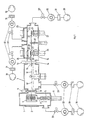
- FIG. 1 shows the lock chamber with a gate 2 to the free atmosphere and with a holder 3 arranged in the chamber for a wafer magazine 4.
- This can be raised and lowered by means of a lifting device provided with a bellows seal 5 and an actuating device 6 such that in each case a specific pane to be treated the magazine 4 is at a suitable height for insertion into the distribution chamber 7 through the opening of the valve 8; the latter is opened or closed as required by an actuator 9.
- a first mechanism 10, 11 is provided for conveying the disk removed from the magazine to the intermediate chamber 15.
- This distributor mechanism has a rotatably arranged robot arm 10, to which a controllable drive device 11 is assigned.
- the robot arm 10 takes a disk from the magazine 4 by means of the disk support 12 when the valve 8 is open and brings it through the opened valve 14 which can be actuated by the auxiliary device 13 into the intermediate chamber 15. If there are several intermediate chambers, the Washer introduced into the intermediate chamber corresponding to the process program.
- Fig. 1 the position of the rotatable robot arm 10, in which it takes over the disc from the magazine 4, with 10 'dash-dotted line, on the other hand, the position in which he passes this with the valve 14 open to the intermediate chamber 15, with 10 in full Lines drawn.
- a second mechanism for handling the discs is housed in the intermediate chamber 15, from which the disks are passed on to the individual connected process chambers 24 and 25, in which they process certain steps, e.g. a coating or etching in the course of a manufacturing process.
- this second mechanism is designed as a rotating arm 20 with grippers 21 for taking over the disks brought by the first mechanism.
- the grippers 21 By correspondingly rotating the grippers 21 along a circular path, the disks can be brought under the openings 22 and 23 located on a circle to the process chambers 24 and 25 and from there by means of lifting devices 26 and 27 (which can be equipped similarly to that in the lock chamber 1) are lifted up into the treatment positions of the individual process chambers or lowered again after a treatment has been carried out and conveyed on to another process station.
- the lifting devices are also equipped with ring seals 28 and 29 which, when fitted to the ceiling of the intermediate chambers around the openings 22 and 23, result in a vacuum-tight shut-off between the intermediate chamber and the process chambers;
- the closed position of the seal 28 is indicated with 28 '.
- FIG. 1 also shows schematically the pumping stations assigned to the various chambers, of which each can consist, for example, of a backing pump 30, a condenser 31, a high vacuum pump 32 and a valve 33. All valves and the pumps can be connected to a control mechanism or a control computer in order to actuate them in accordance with a desired process sequence (which does not form the subject of the present invention).
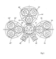
- the reference numeral 40 designates the central distribution chamber into which the panes to be treated can be introduced via lock chambers 42 and can be removed again after the treatment.
- the intermediate chambers 44, 44 'and 44 ⁇ are connected on three sides and each of these intermediate chambers are assigned three process chambers in the exemplary embodiment, which are shown schematically in FIG. 2 with 45, 46 and 47 or 45', 46 ' 47 'and 45 ⁇ , 46 ⁇ and 47 ⁇ are designated.
- the connection between the distribution chamber and the connected intermediate chambers is given by the valves 48 or 48 'or 48', which are opened and closed accordingly by a control device for the processes to be carried out.
- first and second mechanisms are accommodated in the central distributor chamber or in the intermediate chambers flanged to them; they provide process-oriented transport of the disks in and out of the individual chambers, similar to that described with reference to the example in FIG. 1.
- Fig. 3 shows the first and second mechanisms used in the embodiment of Fig. 1 and the interaction of the two. Where used, the reference numerals are the same as in FIG. 1.
- a plate is fastened to the robot arm 10 controlled by the drive device 11, which plate engages under the disks and takes them over from the cassette in the lock chamber and then after retraction and rotation of the Robot arms from the position 10 'in the position 10 (see Fig. 1) to the gripper 21 in the chamber 15.
- the second mechanism the disks are then brought into the correct position relative to the opening of a process chamber by rotating about the axis 20 '.
- the device according to FIG. 11 is designed in such a way that the disk in question is already in this position opposite the process chamber 24 after transfer to the second mechanism.
- the method according to the invention for operating the vacuum system is explained with reference to FIG. 1 and is characterized in that the first transport mechanism 10, 11, 12 arranged in the distribution chamber 7 successively removes and opens a workpiece from a magazine 4 in the lock 1 transported through the distribution chamber 7 into an intermediate chamber 15 and the second transport mechanism 20, 21 arranged in the intermediate chamber takes over the workpiece from the first transport mechanism 10, 11, 12 and in one to the connection opening holds 22 or 23 between the intermediate chamber 15 and a process chamber 24 or 25 coaxial position.
- this operating method in the presence of a plurality of process chambers 24, 25 assigned to an intermediate chamber 15 and below the connecting openings 22, 23 between the latter and the intermediate chamber 15 arranged in this lifting devices 26, 27 for the up and down transport of the panes into and out of the process chambers characterized in that the second transport mechanism 20, 21 deposits the workpiece taken over from the first transport mechanism 10, 11, 12 on one of the lifting devices 26, 27, which transports the workpiece into one of the process chambers 24, 25 located above the lifting devices, and that the workpiece is transported back to the starting position in the same way with the reverse order of the transport steps.
- the method for operating the vacuum system can in particular be designed in such a way that, in the presence of at least two process chambers 24, 25 each assigned to an intermediate chamber 15, each of these process chambers is activated and regenerated alternately after loading during successive time intervals, the process chamber being regenerated another chamber is put into operation.
- a certain period of time during which a disk is treated in this chamber is followed by a period of time during which this chamber is regenerated.
- this can be carried out alternately, so that the regeneration phase and the treatment phase are constantly exchanged.
- the method for operating the vacuum system can also be designed according to the invention in such a way that a magazine with a supply instead of a lifting device 26 or 27 is placed in an intermediate chamber 15 Disks is arranged and that an intermediate chamber with several, for example, three of these assigned process chambers is then put into operation as a unit that is functional independently of the rest of the vacuum system and, in other words, can work autonomously if, for example, the other parts of the vacuum system fail due to a malfunction.
- the vacuum system in each existing intermediate chamber has lifting devices which serve to bring a disc placed on the lifting device into a process chamber arranged above the intermediate chamber.
- the disk-shaped workpiece must be secured on the base of the lifting device, i.e. the workpiece must be held on the edge so that it maintains a certain position.
- gripper-like leaf springs for holding the workpiece, for example in the form of a disk, which encompass the disk edge.
- These holding means can be brought into an open and a closed position in which they hold the disc.
- This treatment is, for example, a coating with 1
- the treatment is an aez process
- the Festhal also etched and the material removed from them can contaminate the pane surface.
- the holding means also cause potential distortions and, as a result, often a kind of courtyard or shadow.
- the pane to be treated should also be positioned with a certain orientation of its position on the base of the lifting device before the pane is transported into the process chamber.
- the wafer has, for example, a contour that deviates from the circular shape, with a circular segment being cut away, which serves to identify the crystal orientation, and the base for the wafer has the same contour that deviates from the circular shape and the pane must be held and transported precisely in relation to this base.
- a lifting device in the form of a special lifting table with holding means is required, which is able to bring the workpiece into an oriented position on the base and to secure the workpiece during transport without it itself are exposed to the effects of this treatment during the treatment of the workpiece.
- the lifting table to be used in the vacuum system should also make it possible for the workpiece to be treated in the process chamber at certain temperatures which are to be kept exactly constant. This may require the application of heat against the underside of the workpiece or cooling.
- the workpiece support is equipped with a heating plate which can be heated by a heating element and with a large number of channels opening onto the surface of the support, which are jointly connected to a gas supply line, in order to provide a gas cushion between the support and the workpiece as a homogeneous one To generate heat conduction for heating the workpiece.
- the gas cushion ensures an absolutely even heat distribution underneath the workpiece. So that the workpiece does not stand out from the base due to the gas cushion, a loose ring serves as the weight load, which comes to rest on the outer edge of the workpiece in the processing station. This ring also has the task of keeping the existing annular gap between the support carrying the workpiece and the cover closed.
- a ring can of course also be used for this purpose, which only rests on the edge of the base but not on the edge of the workpiece, so that it can also be transported exposed. This makes it possible to process either an exposed or an edge-secured workpiece with the same device, depending on what type of processing is currently required.
- the ring preferably lies along the entire edge of the workpiece, if a sealing effect for the gas cushion between the workpiece and the base is to be achieved.
- the ring can be attached in a gas-tight manner to the housing of the vacuum system by means of a bellows, wherein the spring action of the bellows can also be used to counteract the pressure of the gas cushion. If, on the other hand, the workpiece is to be treated to the extreme edge, the ring can also rest on the workpiece edge with hooks arranged on the inner edge, so that the majority of the workpiece edge is machined in addition to these hook areas.
- the lifting table with the holding members pivotably arranged in and out of holding engagement has the advantage that the holding members protected behind the cover in the out of holding engagement position cannot stick to the workpiece due to the effects of the treatment.
- the pivotable holding members in their position pivoted inward against the workpiece, fulfill the function of separating the workpiece from the ring by tearing when the lifting table returns to the starting position.
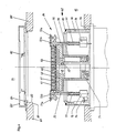
- FIG. 4 shows the essential parts of one of the lifting devices 26 and 27 shown in FIG. 1, which are each designed as a lifting table for moving a workpiece up and down within the intermediate chamber 15.
- the lifting table 26 is shown in FIG. 4 in the so-called loading position, in which a disk-shaped workpiece 61 is placed on the workpiece support 62 consisting of several parts, specifically on the central part 63, which in the example shown is equipped with a heating plate 64 which is heated by a heating element 65 and which heating plate is provided with a plurality of vertical bores 66 through which a gas passes between the disc-shaped Workpiece 61 and the top of the heating plate 64 can reach.
- the heating element 65 can heat the heating plate 64 to temperatures above 500 ° C.
- the heated gas then serves as a heat conduction means in order to heat the workpiece completely uniformly over its surface.
- the same gas is preferably used, which is also used in a process carried out in the vacuum system, because a gas-tight seal at the edge of the heating plate is very difficult to achieve.
- a flange 67 located below the heating plate 64 serves for fastening the heating element 65 and for supplying gas to the bores 66 in the heating plate.
- This heating plate and the flange 67 are fastened together on a further flange 68, which contains channels 69 of a rapid cooling device.
- the flange 68 is connected in a heat-insulating manner by means of a thin-walled tube 70 to a part 71, which is also cooled and is electrically insulated, and is connected in a gas-tight manner.
- the workpiece support 62 which can be moved up and down, also includes holding members 72 and 73 which can be pivoted about it. From FIG. 7 it can be seen that two of these holding members 72 are present on one side and a holding member 73 is present on the opposite side. After the workpiece 61 has been placed on the support 62, the holding members are pivoted from a position 72a or 73a, in which they are not in engagement with the workpiece, to the position 72b or 73b, in which they are in engagement. For this purpose, they are pivoted about an axis 74 parallel to the central axis of the workpiece support 62. If necessary, this movement also corrects the position of the workpiece 62 on the support, which will be explained in more detail later with reference to FIG. 7.
- the holding members 72 and 73 each consist of a rod-shaped body 75 which is in a bearing 76 about its axis is rotatably mounted. Each holding element can be pressed down against the action of a compression spring 77 supported on the bearing and surrounding the rod-shaped body 15.
- the workpiece support 62 which can be moved up and down, also includes a cylindrical outer part 78, within which the holding members 72 and 73 are arranged so as to be pivotable.
- the lifting table 26 extends from below through a recess in the chamber wall 79 of the intermediate chamber 15, the lifting table being flanged against this wall 79 on the underside. 1 and 4 there is a process chamber 24 above the intermediate chamber 15, which are connected to one another via a connecting opening 22 in the wall 80 located between them.
- the upper edge of the cylindrical outer part 78 comes into sealing contact with a seal 82 against a region formed on this wall 80 at the edge of the opening 22 as the lift table 26 is raised in order to treat a workpiece 61 within the process chamber 24.
- the lifting table 26 thus serves not only for the up and down transport of the workpieces, but also represents a valve which separates the intermediate chamber 15 from the process chamber in a gas-tight manner.
- an annular cover 83 located within the process chamber 24 is fastened to the chamber wall 80.
- a loose ring 84 rests on the edge of the chamber wall and is guided in the opening 22.
- this ring 84 has hooks 85 arranged distributed around the circumference.
- the workpiece support 62 is shown raised to an intermediate station.
- the workpiece 61 lying on the base has slightly raised the loose ring 84 and the ring hangs with its hooks 85 on the edge of the workpiece, so that the latter is against the heating plate 64 is pressed and secured against slipping sideways.
- the ring also serves as a weight load to counteract the aforementioned gas cushion between the workpiece and the heating plate.
- the ring 84 has the task of covering the annular gap present between the cover 83 and the workpiece which has been raised on the base, in order to protect the parts underneath from the effects of the treatment taking place in the process chamber.
- the holding members 72 and 73 are shown in Fig. 5 in the position out of holding engagement, ie pivoted outwards.
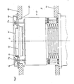
- Fig. 6 the workpiece support 62 is shown raised to the end position and is in the processing position. This position is reached when the cylindrical outer part 78 of the base 62 is moved against the edge of the chamber wall 80 which is designed as a valve seat 81. The workpiece 61 then projects beyond the cover 83 and is fully exposed to the treatment in the process chamber 24.
- the holding members 72 and 73 are pressed against the cover 83 on the underside, wherein they are pushed inward against the action of the spring 77. In this position, below the cover 83, the holding members 72 and 73 are protected from the effects of the workpiece treatment.
- FIG. 6 shows different embodiments on the left and on the right half, and the movable ring 84 can only be seen in the left half.
- an annular shield 86 is shown which is fastened to the base 62 and which covers the annular gap between the cover 83 and the workpiece in order to protect the parts underneath from the effects of the process chamber.
- This shielding in the form of a channel has to absorb gradually build-up of coverings during coating processes, for example an aluminum up to 7mm thick nium layer. Such layers can also grow on the cover 83, which is why this cover can be easily replaced from the process chamber 24, which also applies to the loose ring 84 and the shield 86.
- the right half of FIG. 6 shows the possible design only with a workpiece support plate, ie without a heating plate
- FIG. 7 shows the loose ring 84 with the hook 85 arranged on the inner edge in a top view from above, as well as the holding members 72 and 73 in cooperation with the disk-shaped workpiece 61 shown in broken lines.
- the viewing direction is from the process chamber 24, when the cover 83 is removed.
- FIG. 7 shows the situation after reaching the workpiece support 62 in the intermediate position according to FIG. 5, but before the holding members 72 and 73 swivel outward.
- the representation according to FIG. 7 is in other words identical to the situation in the loading position according to FIG 4 after the holding members have been pivoted inward, if one imagines the loose ring 84 lying in a plane above the workpiece 61 and the holding members in FIG.
- the two aforementioned situations are repeated when the workpiece is returned from the machining position to the loading position.
- the workpiece orientation is corrected twice in each machining cycle with back and forth transport, namely when the holding members 72 and 73 are pivoted inward into the position shown in FIG.
- the two holding members 72 are pivoted about axes 87 parallel to the central axis, which are not shown in FIG. 4, and pressed hard against a mechanical stop.
- the holding member 73 is pivoted inward about the axis 74 also shown in FIG. 4.
- the holding member presses the workpiece 61 with the segment edge 6la (or flat) against the two holding members 72 and thereby corrects the Workpiece orientation if the holding members 72 are not simultaneously touched by the segment edge 61a, ie if the holding members 72 and this edge 6la were not parallel from the start.
- a displacement of the workpiece in the direction of the axis 88 by the process of the orientation correction can be limited in both positions, namely in the loading position by the means not described here for the workpiece transport from one station to another and in the intermediate station through the loose ring 84 or thereon fastened parts.
Landscapes
- Container, Conveyance, Adherence, Positioning, Of Wafer (AREA)
- Coating Apparatus (AREA)
- Physical Vapour Deposition (AREA)
- Drying Of Semiconductors (AREA)
- Applications Or Details Of Rotary Compressors (AREA)
- Manipulator (AREA)
- Fluid-Driven Valves (AREA)
- Electron Tubes For Measurement (AREA)
Abstract
Die Vakuumanlage zum Behandeln von scheibenförmigen Werkstücken weist eine zentrale Verteilerkammer (7) auf, in welche die Werkstücke von einer Schleuse durch eine mittels eines Verschlusselements (8) verschliessbare Verbindungsöffnung mit Hilfe eines in der Verteilerkammer angeordneten Transport-Mechanismus (10,11,12), vorzugsweise in Form eines Robotarms, eingebracht werden. An die Verteilerkammer (7) schliessen ferner über den Umfang derselben verteilt Zwischenkammern (15) als auswechselbare Module an, wobei die Verbindung zwischen diesen bei jeder Anschlussstelle durch ein Verschlusselement (14) geschlossen werden kann. Eine Zwischenkammer (15) steht mit mindestens einer Prozesskammer (24,25) über eine zugeordnete Verbindungs-öffnung (22,23) in Verbindung, welch letztere zwecks Abtrennung der Prozesskammer von der Zwischenkammer erschliessbar ist. In der Zwischenkammer (15) ist ein weiterer Transport-Mechanismus (20,21) zwecks Uebernahme der Werkstücke vom ersten Transport-Mechanismus (10,11 ,12) angeordnet, welcher die Werkstücke auf einen unterhalb einer Prozesskammer (24,25) angeordneten Hubtisch (26,27) ablegt. Dieser bringt das Werkstück in die zugeordnete Prozesskammer und trennt dabei gleichzeitig diese von der Verteilerkammer (15) ab. Vorzugsweise sind jeder Zwischenkammer (15) mehrere Prozeskkammern (24,25) zugeordnet. Die Verschlusselemente (8,14,26,27) an den Verbindungsöffnungen zwischen den Kammern (7,15,24,25) werden bei der Durchführung von Prozessen so gesteuert, dass kein unerwünschter Uebertritt von Gasen oder Partikeln von einer Prozesskammer in die andere stattfinden kann. 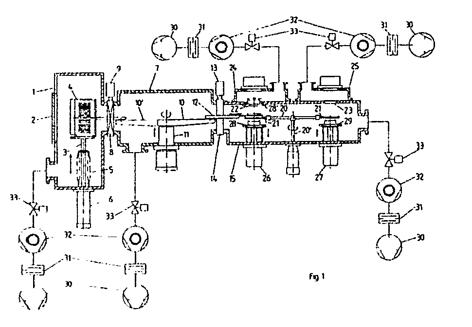
Description
Die vorliegende Erfindung betrifft eine Vakuumanlage zum Behandeln von Werkstücken, mit mindestens einer Prozesskammer für die Werkstücke und einer zentralen evakuierbaren Verteilerkammer, in welche die Werkstücke über Schleusen mittels eines ersten TransportMechanismus ein- und nach Behandlung wieder ausgebracht werden.The present invention relates to a vacuum system for treating workpieces, with at least one process chamber for the workpieces and a central evacuable distributor chamber, into which the workpieces are introduced via locks by means of a first transport mechanism and then removed again after treatment.
Aus der Zeitschrift Solid State Technology/Oktober 1987 (Seiten 55/56) ist eine solche Mehrkammeranlage für die Behandlung von Siliziumwafern bekannt, die in einer zentralen Verteilerkammer einen Robotarm aufweist, der die einzelnen zu behandelnden Halbleiterscheiben gemäss einem vorgegebenen Programm den einzelnen Prozesskammern zuführt bzw. sie nach Durchführung eines Prozesses, z.B. einer Beschichtung, wieder daraus entnimmt. An eine solche zentrale Verteilerkammer kann eine Mehrzahl von Prozesskammern angeschlossen sein, wobei die Halbleiterscheiben, ohne dass sie zwischen den einzelnen Prozessen in die freie Atmosphäre übergeführt werden müssen, durch die Verteilerkammer hindurch von einer Prozesskammer in die andere befördert werden können. Bei sehr empfindlichen Prozessen besteht dabei aber die Gefahr, dass Restgase, die z.B. in einem Verfahrensschritt in einer Prozesskammer benötigt werden, in eine andere gelangen, wo sie den dort durchzuführenden Prozess stören, oder dass Partikel die bei dem einen oder anderen Prozessschritt etwa aufgewirbelt werden, verschleppt werden. Auch können mit den noch unbehandelten Halbleiterscheiben aus dem Aussenraum in die Verteilerkammer eingebrachte Partikel beim Vorbeibewegen an teilweise bereits behandelten Halbleiterscheiben auf diese gelangen und die an diesen noch unbehandelten Halbleiterscheiben nachfolgend durchzuführenden Prozesse beeinträchtigen.Such a multi-chamber system for the treatment of silicon wafers is known from the magazine Solid State Technology / October 1987 (pages 55/56), which has a robot arm in a central distributor chamber which feeds the individual semiconductor wafers to be treated to the individual process chambers in accordance with a predetermined program after removal of a process, for example a coating, takes it out of it again. A plurality of process chambers can be connected to such a central distributor chamber, the semiconductor wafers being able to be conveyed through the distributor chamber from one process chamber to the other without having to be transferred into the free atmosphere between the individual processes. In the case of very sensitive processes, however, there is a risk that residual gases that are required, for example, in one process step in one process chamber, will get into another, where they interfere with the process to be carried out there, or that particles that are whirled up in one or the other process step , be kidnapped. Can also with the still untreated semiconductor wafers from the outside in the distribution chamber Particles that have been introduced move past semiconductor wafers that have already been treated and adversely affect the processes to be carried out on these still untreated semiconductor wafers.
Es ist schon vorgeschlagen worden, die einzelnen Prozessschritte durch Druckstufenschleusen, die den Prozesskammern vorgeschaltet werden, z.B. mittels eines sogenannten Druckstufensystems, das aus drei separat auspumpbaren Vakuumkammern besteht und wobei die Wafer durch entsprechende Schlitze in den Wänden zwischen den einzelnen Kammern hindurch in die Prozesskammern befördert werden, zu entkoppeln. Hauptzweck der Druckstufenschleusen war dabei aber lediglich die Aufrechterhaltung einer Druckdifferenz zwischen den verschiedenen Räumen des Vakuumsystems.It has already been suggested that the individual process steps be carried out by compression locks which are connected upstream of the process chambers, e.g. by means of a so-called compression stage system, which consists of three vacuum chambers which can be pumped out separately and the wafers are conveyed through corresponding slots in the walls between the individual chambers into the process chambers. The main purpose of the compression locks was only to maintain a pressure difference between the different rooms of the vacuum system.
Der vorliegenden Erfindung liegt nun die Aufgabe zugrunde, eine Vakuumanlage mit einer Mehrzahl von Prozesskammern bereitzustellen, bei der die erwähnte Gefahr der Verschleppung von Restgasen und Partikeln von einer Prozesskammer in eine andere bzw. von einem Werkstück auf ein anderes auf ein Minimum reduziert oder überhaupt ausgeschlossen ist.The present invention is based on the object of providing a vacuum system with a plurality of process chambers, in which the aforementioned risk of carryover of residual gases and particles from one process chamber to another or from one workpiece to another is reduced to a minimum or is eliminated at all is.
Zur Lösung der Aufgabe weist die Vakuumanlage die Merkmale nach Anspruch 1 auf. In bevorzugter Ausführungsform der Erfindung können an die Verteilerkammer mehrere Zwischenkammern mit zugeordneten Prozesskamern angeschlossen sein und/oder einer Zwischenkammer mehrere Prozesskammern zugeordnet sein.To achieve the object, the vacuum system has the features of claim 1. In a preferred embodiment of the invention, several intermediate chambers with associated process chambers can be connected to the distribution chamber and / or several process chambers can be assigned to an intermediate chamber.
Ein Ausführungsbeispiel der Erfindung wird anhand der anliegenden Zeichnungen näher erläutert. Es zeigen:
- Fig. 1 in schematischer Darstellung einen Vertikalschnitt durch die Vakuumanlage;
- Fig. 2 schematisch in Draufsicht die Vakuumanlage mit drei Zwischenkammern und neun Prozesskammern;
- Fig. 3 in schaubildlicher Darstellung das Prinzip der Uebergabe einer Scheibe vom ersten zum zweiten Transport-Mechanismus;
- Fig. 4 einen Vertikalschnitt durch einen in einer Zwischenkammer angeordneten Hubtisch mit Haltevorrichtung für die Scheibe, in einer ersten Hubstellung;
- Fig. 5 den Hubtisch gemäss Fig. 4, in einer Zwischenstellung;
- Fig. 6 den Hubtisch gemäss Fig. 4, in der Endstellung bei Behandlung der Scheibe in der Prozesskammer, und
- Fig. 7 eine Ansicht von oben auf zum Hubtisch gehörende Teile.
- Figure 1 is a schematic representation of a vertical section through the vacuum system.
- 2 shows a schematic top view of the vacuum system with three intermediate chambers and nine process chambers;
- 3 shows a diagram of the principle of transferring a disk from the first to the second transport mechanism;
- 4 shows a vertical section through a lifting table arranged in an intermediate chamber with a holding device for the disk, in a first lifting position;
- FIG. 5 the lifting table according to FIG. 4, in an intermediate position;
- 6, the lifting table according to FIG. 4, in the end position when the disc is treated in the process chamber, and
- Fig. 7 is a top view of parts belonging to the lifting table.
Figur 1 zeigt die Schleusenkammer mit einem Tor 2 zur freien Atmospähre und mit in der Kammer angeordneter Halterung 3 für ein Wafermagazin 4. Dieses kann mittels einer mit Faltenbalgdichtung 5 und Betätigungsvorrichtung 6 versehenen Hubeinrichtung so gehoben und gesenkt werden, dass jeweils eine bestimmte zu behandelnde Scheibe des Magazins 4 in passender Höhe liegt für die Einführung in die Verteilerkammer 7 durch die Oeffnung des Ventils 8 hindurch; letzteres wird durch eine Betätigungseinrichtung 9 nach Bedarf geöffnet oder geschlossen.FIG. 1 shows the lock chamber with a
In der Verteilerkammer 7 ist ein erster Mechanismus 10,11 zur Weiterbeförderung der jeweils dem Magazin entnommenen Scheibe an die Zwischenkammer 15 vorgesehen. Dieser Verteilermechanismus weist einen drehbar angeordneten Robotarm 10 auf, dem eine steuerbare Antriebsvorrichtung 11 zugeordnet ist. Der Robotarm 10 entnimmt beim Betrieb dem Magazin 4 mittels der Scheibenauflage 12 bei geöffnetem Ventil 8 jeweils eine Scheibe und bringt sie durch das geöffnete, durch die Hilfseinrichtung 13 betätigbare Ventil 14 in die Zwischenkammer 15. Bei Vorhandensein mehrerer Zwischenkammern wird die Scheibe in die dem Verfahrensprogramm jeweils entsprechende Zwischenkammer eingebracht.In the distribution chamber 7, a
In der Fig. 1 ist diejenige Stellung des drehbaren Robotarms 10, in welcher er die Scheibe vom Magazin 4 übernimmt, mit 10′ strichpunktiert, dagegen die Stellung, in welcher er diese bei geöffnetem Ventil 14 an die Zwischenkammer 15 weitergibt, mit 10 in vollen Linien gezeichnet. In der Zwischenkammer 15, von welcher aus die Weitergabe der Scheiben an die einzelnen angeschlossenen Prozesskammern 24 und 25 erfolgt, in denen sie bestimmten Prozessschritten, z.B. einer Beschichtung oder einer Aetzung im Zuge eines Herstellungsverfahrens unterworfen werden, ist ein zweiter Mechanismus zur Handhabung der Scheiben untergebracht.In Fig. 1, the position of the
Dieser zweite Mechanismus ist ähnlich wie der erste als Dreharm 20 mit Greifern 21 für die Uebernahme der vom ersten Mechanismus überbrachten Scheiben ausgestaltet. Durch entsprechende Drehung der Greifer 21 längs einer Kreisbahn können die Scheiben unter die auf einem Kreis befindlichen Oeffnungen 22 und 23 zu den Prozesskammern 24 und 25 gebracht und von dort mittels Hubeinrichtungen 26 und 27 (die ähnlich wie diejenige in der Schleusenkammer 1 ausgestattet werden können) in die Behandlungspositionen der einzelnen Prozesskammern hochgehoben bzw. nach Durchführung einer Behandlung wieder abgesenkt und zu einer anderen Prozessstation weiterbefördert werden. Im gezeichneten Ausführungsbeispiel sind die Hubeinrichtungen noch mit Ringdichtungen 28 und 29 ausgestattet, die beim Anpassen derselben an die Decke der Zwischenkammern rund um die Oeffnungen 22 und 23 eine vakuumdichte Absperrung zwischen der Zwischenkammer und den Prozesskammern ergeben; in Fig. 1 ist die Schliessposition der Dichtung 28 mit 28′ angedeutet.Similar to the first, this second mechanism is designed as a rotating
Die Fig. 1 zeigt noch schematisch die den verschiedenen Kammern zugeordneten Pumpstände, von denen jeder z.B. aus einer Vorpumpe 30, einem Kondensator 31, einer Hochvakuumpumpe 32 und einem Ventil 33 bestehen kann. Sämtliche Ventile und die Pumpen können mit einem Steuermechanismus bzw. einem Steuercomputer verbunden werden, um sie einem gewünschten Prozessablauf entsprechend (welcher nicht den Gegenstand der vorliegenden Erfindung bildet) zu betätigen.1 also shows schematically the pumping stations assigned to the various chambers, of which each can consist, for example, of a
In Fig. 1 ist zwar nur eine vereinfachte Anordnung mit nur einer an die Kammer 7 angeschlossenen Zwischenkammer 15 dargestellt, doch ist es für den Fachmann ersichtlich, dass mit der Verteilerkammer 7 auch zwei oder mehrere Zwischenkammern verbunden werden könnten, von denen aus die Scheiben einem vorgegebenen Programm entsprechend durch den zweiten Mechanismus an die an die Zwischenkammern angeschlossenen Prozesskammern verteilt werden können.Although only a simplified arrangement with only one
Das Schema einer solchen Anordnung zeigt die Fig. 2. Mit dem Bezugszeichen 40 ist die zentrale Verteilerkammer bezeichnet, in welche die zu behandelnden Scheiben über Schleusenkammern 42 ein- und nach der Behandlung wieder ausgebracht werden können. An diese zentrale Verteilerkammer sind an drei Seiten die Zwischenkammern 44, 44′ und 44˝ angeschlossen und jeder dieser Zwischenkammern sind im Ausführungsbeispiel je drei Prozesskammern zugeordnet, die in der Fig. 2 schematisch mit 45, 46 und 47 bzw. 45′, 46′ 47′ und 45˝, 46˝ und 47˝ bezeichnet sind. Die Verbindung zwischen der Verteilerkammer und den angeschlossenen Zwischenkammern ist durch die Ventile 48 bzw. 48′ bzw. 48˝ gegeben, die von einer Steuereinrichtung den durchzuführenden Prozessen entsprechend geöffnet und geschlossen werden. Die oben erwähnten (in Fig. 2 nicht dargestellten) ersten und zweiten Mechanismen sind in der zentralen Verteilerkammer bzw. in den an diese angeflanschten Zwischenkammern untergebracht; sie besorgen den prozessgerechten Transport der Scheiben in die bzw. aus den einzelnen Kammern, ähnlich wie anhand des Beispiels der Fig. 1 beschrieben.The diagram of such an arrangement is shown in FIG. 2. The
Die Fig. 3 zeigt den im Ausführungsbeispiel der Fig. 1 verwendeten ersten und zweiten Mechanismus und das Zusammenwirken der beiden. Die Bezugsziffern sind, soweit verwendet, dieselben wie in Fig. 1. An dem von der Antriebsvorrichtung 11 gesteuerten Robotarm 10 ist eine Platte so befestigt, welche unter die Scheiben greifend diese von der Kassette in der Schleusenkammer übernimmt und sie sodann nach Rückziehen und Drehung des Robotarmes aus der Position 10′ in die Position 10 (siehe Fig. 1) an die Greifer 21 in der Kammer 15 abgibt. Durch den zweiten Mechanismus werden die Scheiben dann durch Drehen um die Achse 20′ in die richtige Position gegenüber der Oeffnung einer Prozesskammer gebracht. Die Vorrichtung gemäss Fig. 1 1 ist so ausgestaltet, dass die betreffende Scheibe schon nach Uebergabe an den zweiten Mechanismus sich in dieser Lage gegenüber der Prozesskammer 24 befindet. In der Darstellung der Fig. 3 wird gerade eine auf der Platte so liegende Scheibe 51 an den Greifer 21 abgegeben (und würde sich somit unterhalb der Oeffnung 22 der Fig. befinden), während eine weitere Scheibe 52 in einer Stellung unterhalb der Oeffnung 23 der Prozesskammer 25 weitergedreht dargestellt ist (bei 3er-Teilung 120° Weiterdrehung).Fig. 3 shows the first and second mechanisms used in the embodiment of Fig. 1 and the interaction of the two. Where used, the reference numerals are the same as in FIG. 1. A plate is fastened to the
Das erfindungsgemässe Verfahren zum Betrieb der Vakuumanlage wird anhand der Fig. 1 erläutert und ist dadurch gekennzeichnet, dass der in der Verteilerkammer 7 angeordnete erste Transport-Mechanismus 10,11 ,12 nacheinander jeweils ein Werkstück aus einem Magazin 4 in der Schleuse 1 entnimmt und auf dem Weg durch die Verteilerkammer 7 in eine Zwischenkammer 15 transportiert und der in der Zwischenkammer angeordnete zweite Transport-Mechanismus 20,21 das Werkstück vom ersten Transport-Mechanismus 10,11,12 übernimmt und in einer zur Verbindungsöff nung 22 oder 23 zwischen der Zwischenkammer 15 und einer Prozesskammer 24 oder 25 koaxialen Lage bereithält. Insbesondere ist dieses Betriebsverfahren bei Vorhandensein mehrerer einer Zwischenkammer 15 zugeordneten Prozesskammern 24,25 und unterhalb der Verbindungsöffnungen 22,23 zwischen letzteren und der Zwischenkammer 15 in dieser angeordneten Hubeinrichtungen 26,27 für den Auf- und Abtransport der Scheiben in und aus den Prozesskammern erfindungsgemäss dadurch gekennzeichnet, dass der zweite Transport-Mechanismus 20,21 das vom ersten Transport-Mechanismus 10,11,12 übernommene Werkstück auf eine der Hubeinrichtungen 26,27 ablegt, die das Werkstück in eine der oberhalb der Hubeinrichtungen befindliche Prozesskammer 24,25 transportiert und dass das Werkstück auf dem selben Weg bei umgekehrter Reihenfolge der Transportschritte zu der Ausgangslage zurücktransportiert wird.The method according to the invention for operating the vacuum system is explained with reference to FIG. 1 and is characterized in that the
Das Verfahren zum Betrieb der Vakuumanlage kann insbesondere so gestaltet werden, dass bei Vorhandensein von mindestens zwei jeweils einer Zwischenkammer 15 zugeordneten Prozesskammern 24,25 jede dieser Prozesskammern während aufeinanderfolgenden Zeitintervallen abwechselnd nach Beschickung in Funktion gesetzt und regeneriert wird, wobei während der Regenerierung einer Prozesskammer die weitere Kammer in Funktion gesetzt wird. Das bedeutet mit anderen Worten, dass bei jeder Prozesskammer auf eine bestimmte Zeitspanne, während der eine Scheibe in dieser Kammer behandelt wird, eine Zeitspanne folgt, während der diese Kammer regeneriert wird. Bei zwei vorhandenen Prozesskammern lässt sich dies abwechselnd durchführen, sodass die Regenerierungsphase und die Behandlungsphase ständig vertauscht werden.The method for operating the vacuum system can in particular be designed in such a way that, in the presence of at least two
Schliesslich lässt sich das Verfahren zum Betrieb der Vakuumanlage erfindungsgemäss auch in der Weise gestalten, dass in einer Zwischenkammer 15 anstelle einer Hubeinrichtung 26 oder 27 ein Magazin mit einem Vorrat an Scheiben angeordnet wird und dass dann eine Zwischenkammer mit mehreren beispielsweise drei dieser zugeordneten Prozesskammern als eine von der übrigen Vakuumanlage unabhängig funktionsfähige Einheit in Betrieb gesetzt wird, die mit anderen Worten autonom arbeiten kann, wenn beispielsweise die übrigen Teile der Vakuumanlage durch eine Betriebsstörung ausfallen.Finally, the method for operating the vacuum system can also be designed according to the invention in such a way that a magazine with a supply instead of a
Wie vorstehend bereits erwähnt worden ist, weist die Vakuumanlage in jeder vorhandenen Zwischenkammer Hubeinrichtungen auf, welche dazu dienen, eine auf der Hubeinrichtung abgelegte Scheibe in eine oberhalb der Zwischenkammer angeordnete Prozesskammer zu bringen. Bei diesem Vorgang muss das scheibenförmige Werkstück auf der Unterlage der Hubeinrichtung gesichert werden, d.h. das Werkstück ist am Rand festzuhalten, damit es eine bestimmte Lage beibehält.As has already been mentioned above, the vacuum system in each existing intermediate chamber has lifting devices which serve to bring a disc placed on the lifting device into a process chamber arranged above the intermediate chamber. During this process, the disk-shaped workpiece must be secured on the base of the lifting device, i.e. the workpiece must be held on the edge so that it maintains a certain position.
Es ist bekannt, zum Festhalten des Werkstückes beispielsweise in Form einer Scheibe greiferartige Blattfedern zu verwenden, die den Scheibenrand umfassen. Diese Festhaltemittel können in eine offene und in eine geschlossene Stellung gebracht werden, in welcher sie die Scheibe festhalten. Dabei entsteht das Problem, dass diese Festhaltemittel in der Prozesskammer auch der darin für die Scheibe durchgeführten Behandlung ausgesetzt sind. Diese Behandlung ist beispielsweise eine Beschichtung mit 1|m Aluminium pro Scheibe bei einem Durchsatz von einer Scheibe pro Minute, was dann zur Folge hat, dass auf den Festhaltemitteln innerhalb von fünf Tagen eine über 7mm starke Aluminiumschicht aufwachsen wird. Es können überhängende Aluminium-Knollen entstehen, die oft zu unerwünschten Abschattungen bei der Beschichtung der Scheibe führen. Es kann auch vorkommen, dass die Scheibe mit den Festhaltemitteln zusammenwächst und dann daran kleben bleibt. Wenn es sich andererseits bei der Behandlung um einen Aezprozess handelt, so werden die Festhal temittel auch mitgeäzt und das von diesen abgetragene Material kann dabei die Scheibenoberfläche verunreinigen. Beim Reinigungsäzen der Scheibe durch Kathodenzerstäubung verursachen die Festhaltemittel auch Potenzialverzerrungen und infolge dessen oft eine Art Hof oder Schatten.It is known to use gripper-like leaf springs for holding the workpiece, for example in the form of a disk, which encompass the disk edge. These holding means can be brought into an open and a closed position in which they hold the disc. This creates the problem that these holding means in the process chamber are also exposed to the treatment carried out therein for the pane. This treatment is, for example, a coating with 1 | m aluminum per disc with a throughput of one disc per minute, which has the consequence that an over 7 mm thick aluminum layer will grow on the holding means within five days. Overhanging aluminum bulbs can occur, which often lead to undesired shadowing when coating the pane. It can also happen that the pane grows together with the holding means and then sticks to it. On the other hand, if the treatment is an aez process, then the Festhal also etched and the material removed from them can contaminate the pane surface. When the disc is etched by cathode sputtering, the holding means also cause potential distortions and, as a result, often a kind of courtyard or shadow.
In vielen Fällen soll die zu behandelnde Scheibe auch noch mit einer bestimmten Orientierung ihrer Lage auf der Unterlage der Hubeinrichtung positioniert sein, bevor die Scheibe in die Prozesskammer transportiert wird. Bei der Behandlung von Halbleiterscheiben für die Herstellung integrierter Mikroelektronik-Bausteine weist die Scheibe beispielsweise eine von der Kreisform abweichende Kontur auf, wobei ein Kreissegment weggeschnitten ist, was zur Kennzeichnung der Kristallorientierung dient, und die Unterlage für die Scheibe hat dieselbe von der Kreisform abweichende Kontur und die Scheibe muss bezüglich dieser Unterlage genau orientiert festgehalten und transportiert werden.In many cases, the pane to be treated should also be positioned with a certain orientation of its position on the base of the lifting device before the pane is transported into the process chamber. In the treatment of semiconductor wafers for the production of integrated microelectronic components, the wafer has, for example, a contour that deviates from the circular shape, with a circular segment being cut away, which serves to identify the crystal orientation, and the base for the wafer has the same contour that deviates from the circular shape and the pane must be held and transported precisely in relation to this base.
Für die Vakuumanlage der eingangs genannten Art ist daher eine Hubeinrichtung in Form eines besonderen Hubtisches mit Festhaltemitteln erforderlich, die in der Lage sind, das Werkstück in eine orientierte Lage auf der Unterlage zu bringen und das Werkstück während des Transports zu sichern, ohne dass sie selbst während der Behandlung des Werkstückes den Einwirkungen dieser Behandlung ausgesetzt sind.For the vacuum system of the type mentioned at the outset, a lifting device in the form of a special lifting table with holding means is required, which is able to bring the workpiece into an oriented position on the base and to secure the workpiece during transport without it itself are exposed to the effects of this treatment during the treatment of the workpiece.
Der in der Vakuumanlage zu verwendende Hubtisch soll es ferner ermöglichen, dass die Behandlung des Werkstücks in der Prozesskammer bei bestimmten und genau konstant zu haltenden Temperaturen erfolgen kann. Hierfür kann die Zuführung von Wärme gegen die Unterseite des Werkstückes oder auch eine Kühlung erforderlich sein.The lifting table to be used in the vacuum system should also make it possible for the workpiece to be treated in the process chamber at certain temperatures which are to be kept exactly constant. This may require the application of heat against the underside of the workpiece or cooling.
Für die Lösung der erstgenannten Aufgabe der lageorientierten Anordnung des Werkstücks auf einer Unterlage und der Sicherung des Transports in die Pro zesskammer dient ein Hubtisch für den Auf- und Abtransport eines scheibenförmigen Werkstückes, der eine bewegbare Werkstück-Unterlage aufweist, an der Halteorgane in und ausser Halteeingriff schwenkbewegbar angeordnet sind, um sie kurz vor Erreichen der Bearbeitungsposition der bewegten Unterlage in die Stellung ausser Halteeingriff zu bringen und in dieser Stellung während der restlichen Transportbewegung der Unterlage in die Bearbeitungsstation bis hinter eine Abdeckung zu bewegen, welche die Halteorgane vor den Einwirkungen durch die Werkstückbehandlung schützt.For the solution of the first-mentioned task of the position-oriented arrangement of the workpiece on a base and the securing of the transport to the Pro Zesskammer serves a lifting table for the up and down transport of a disk-shaped workpiece, which has a movable workpiece support on the holding members in and out of holding engagement are pivotally arranged to bring them shortly before reaching the processing position of the moving support in the position out of holding engagement and in this position during the remaining transport movement of the base into the processing station to move behind a cover which protects the holding members from the effects of the workpiece treatment.
Zur Lösung der weiteren Aufgabe ist die Werkstück-Unterlage mit einer durch ein Heizelement aufheizbaren Heizplatte und mit einer Vielzahl von an der Oberfläche der Unterlage mündenden Kanälen ausgestattet, welche gemeinsam an eine Gaszuführungsleitung angeschlossen sind, um zwischen der Unterlage und dem Werkstück ein Gaspolster als homogenes Wärmeleitungsmittel zum Erhitzen des Werkstückes zu erzeugen. Das Gaspolster sorgt für eine absolut gleichmässige Wärmeverteilung unterhalb des Werkstücks. Damit das Werkstück durch das Gaspolster sich nicht von der Unterlage abhebt, dient als Gewichtsbelastung ein loser Ring, der in der Bearbeitungsstation auf dem Aussenrand des Werkstücks aufzuliegen kommt. Dieser Ring hat ausserdem noch die Aufgabe, den vorhandenen Ringspalt zwischen der das Werkstück tragenden Unterlage und der Abdeckung geschlossen zu halten. Zu diesem Zweck kann natürlich auch ein Ring verwendet werden, der nur am Rand der Unterlage aufliegt aber nicht am Rand des Werkstückes, sodass dieses auch freiliegend transportiert werden kann. Damit ist es möglich, mit derselben Einrichtung entweder ein freiliegendes oder ein am Rand gesichertes Werkstück zu bearbeiten, je nach dem welche Art der Verarbeitung gerade verlangt wird. Der Ring liegt vorzugsweise längs des ganzen Werkstückrands auf, wenn eine Dichtwirkung für das Gaspolster zwischen dem Werkstück un der Unterlage erzielt werden soll. In diesem Fall kann der Ring mittels eines Federbalgs gasdicht am Gehäuse der Vakuumanlage befestigt sein, wobei auch die Federwirkung des Federbalgs ausgenutzt werden kann, um dem Druck des Gaspolsters entgegenzuwirken. Wenn hingegen das Werkstück bis zum äussersten Rand behandelt werden soll, kann der Ring auch mit am Innenrand angeordneten Haken am Werkstückrand aufliegen, sodass ausser diesen Hakenbereichen der grösste Teil des Werkstückrands bearbeitet wird.To solve the further task, the workpiece support is equipped with a heating plate which can be heated by a heating element and with a large number of channels opening onto the surface of the support, which are jointly connected to a gas supply line, in order to provide a gas cushion between the support and the workpiece as a homogeneous one To generate heat conduction for heating the workpiece. The gas cushion ensures an absolutely even heat distribution underneath the workpiece. So that the workpiece does not stand out from the base due to the gas cushion, a loose ring serves as the weight load, which comes to rest on the outer edge of the workpiece in the processing station. This ring also has the task of keeping the existing annular gap between the support carrying the workpiece and the cover closed. A ring can of course also be used for this purpose, which only rests on the edge of the base but not on the edge of the workpiece, so that it can also be transported exposed. This makes it possible to process either an exposed or an edge-secured workpiece with the same device, depending on what type of processing is currently required. The ring preferably lies along the entire edge of the workpiece, if a sealing effect for the gas cushion between the workpiece and the base is to be achieved. In this case, the ring can be attached in a gas-tight manner to the housing of the vacuum system by means of a bellows, wherein the spring action of the bellows can also be used to counteract the pressure of the gas cushion. If, on the other hand, the workpiece is to be treated to the extreme edge, the ring can also rest on the workpiece edge with hooks arranged on the inner edge, so that the majority of the workpiece edge is machined in addition to these hook areas.
Der Hubtisch mit den in und ausser Halteeingriff schwenkbewegbar angeordneten Halteorganen hat den Vorteil dass die in der Stellung ausser Halteeingriff hinter der Abdeckung geschützten Halteorgane mit dem Werkstück durch die Einwirkungen der Behandlung nicht verkleben können. Wenn jedoch das Werkstück mit dem am Rand aufliegenden Ring verklebt, erfüllen die schwenkbewegbaren Halteorgane in ihrer gegen das Werkstück einwärts geschwenkten Stellung die Funktion, bei der Rückbewegung des Hubtisches in die Ausgangslage das Werkstück durch Abreissen vom Ring zu trennen.The lifting table with the holding members pivotably arranged in and out of holding engagement has the advantage that the holding members protected behind the cover in the out of holding engagement position cannot stick to the workpiece due to the effects of the treatment. However, if the workpiece is glued to the ring resting on the edge, the pivotable holding members, in their position pivoted inward against the workpiece, fulfill the function of separating the workpiece from the ring by tearing when the lifting table returns to the starting position.
Fig. 4 zeigt die wesentlichen Teile einer der in Fig. 1 dargestellten Hubeinrichtungen 26 bzw. 27, die jeweils als Hubtisch zum Auf- und Abbewegen eines Werkstücks innerhalb der Zwischenkammer 15 ausgebildet sind. Der Hubtisch 26 ist in Fig. 4 in der sogenannten Ladeposition dargestellt, in welcher ein scheibenförmiges Werkstück 61 auf der aus mehreren Teilen bestehenden Werkstück-Unterlage 62 abgelegt ist, und zwar auf dem Zentralteil 63, der im dargestellten Beispiel mit einer Heizplatte 64 ausgestattet ist, die durch ein Heizelement 65 aufgeheizt wird und welche Heizplatte mit einer Vielzahl von vertikalen Bohrungen 66 versehen ist, durch welche hindurch ein Gas zwischen das scheibenförmige Werkstück 61 und die Oberseite der Heizplatte 64 gelangen kann. Das Heizelement 65 kann die Heizplatte 64 auf Temperaturen bis über 500°C aufheizen und das erhitzte Gas dient dann als Wärmeleitungsmittel um das Werkstück vollkommen gleichmässig über seine Fläche zu erhitzen. Man verwendet hierfür vorzugsweise dasselbe Gas, das auch bei einem in der Vakuumanlage durchgeführten Prozess verwendet wird, weil eine gasdichte Abdichtung am Rand der Heizplatte nur sehr schwer zu erreichen ist.FIG. 4 shows the essential parts of one of the
Ein unterhalb der Heizplatte 64 befindlicher Flansch 67 dient zur Befestigung des Heizelements 65 und für die Gaszufuhr zu den Bohrungen 66 in der Heizplatte. Diese Heizplatte und der Flansch 67 sind zusammen auf einem weiteren Flansch 68 befestigt, der Kanäle 69 einer Schnellkühleinrichtung enthält. Der Flansch 68 ist mittels eines dünnwandigen Rohrs 70 wärmeisolierend mit einem ebenfalls gekühlten und elektrisch isoliert befestigten Teil 71 gasdicht verbunden.A
Zur auf- und abbewegbaren Werkstück-Unterlage 62 gehören ferner schwenkbewegbar an diese angeordnete Halteorgane 72 und 73. Aus Fig. 7 ist erkennbar, dass auf der einen Seite zwei dieser Halteorgane 72 vorhanden sind und auf der gegenüberliegenden Seite ein Halteorgan 73 vorhanden ist. Nach dem Ablegen des Werkstücks 61 auf der Unterlage 62 werden die Halteorgane von einer Stellung 72a bzw. 73a, in der sie sich ausser Halteeingriff am Werkstück befinden, in die Stellung 72b bzw. 73b verschwenkt, in der sie sich in Halteeingriff befinden. Zu diesem Zweck werden sie um eine zur Mittelachse der Werkstück-Unterlage 62 parallele Achse 74 verschwenkt. Bei dieser Bewegung erfolgt nötigenfalls auch eine Korrektur der Lage des Werkstücks 62 auf der Unterlage, was später noch im einzelnen anhand der Fig. 7 erläutert wird. Die Halteorgane 72 und 73 bestehen jeweils aus einem stangenförmigen Körper 75, der in einem Lager 76 um seine Achse drehbar gelagert ist. Gegen die Wirkung einer auf dem Lager abgestützten und den stangenförmigen Körper 15 umschiessenden Druckfeder 77 kann jedes Halteorgan nach unten gedrückt werden.The
Zur auf- und abbewegbaren Werkstück-Unterlage 62 gehört ferner ein zylindrischer Aussenteil 78, innerhalb welchem die Halteorgane 72 und 73 schwenkbewegbar angeordnet sind. Wie auch aus Fig. 1 hervorgeht, erstreckt sich der Hubtisch 26 von unten durch eine Ausnehmung in der Kammerwand 79 der Zwischenkammer 15, wobei der Hubtisch unterseitig gegen diese Wand 79 angeflanscht ist. Oberhalb der Zwischenkammer 15 befindet sich gemäss Fig. 1 und 4 eine Prozesskammer 24, die über eine Verbindungsöffnung 22 in der dazwischen befindlichen Wand 80 miteinander in Verbindung stehen. Gegen einen an dieser Wand 80 am Rand der Oeffnung 22 als Ventilsitz 81 ausgebildeten Bereich kommt die Oberkante des zylindrischen Aussenteils 78 mit einer Dichtung 82 in Dichtungskontakt, wenn der Hubtisch 26 angehoben ist, um ein Werkstück 61 innerhalb der Prozesskammer 24 zu behandeln. Der Hubtisch 26 dient somit nicht nur für den Auf- und Abtransport der Werkstücke, sondern stellt gleichzeitig ein Ventil dar, welches die Zwischenkammer 15 von der Prozesskammer gasdicht abtrennt.The
In Fig. 4 ist an der Kammerwand 80 eine innerhalb der Prozesskammer 24 befindliche ringförmige Abdekkung 83 befestigt. Unterhalb dieser Abdeckung liegt ein loser Ring 84 auf dem Rand der Kammerwand auf und ist in der Oeffnung 22 geführt. Am Innenrand besitzt dieser Ring 84 umfangsmässig verteilt angeordnete Haken 85.4, an
In Fig. 5 ist die Werkstück-Unterlage 62 in eine Zwischenstation hochgefahren dargestellt. Dabei hat das auf der Unterlage liegende Werkstück 61 den losen Ring 84 etwas angehoben und der Ring hängt mit seinen Haken 85 am Rand des Werkstückes, sodass dieses gegen die Heizplatte 64 angedrückt wird und gegen seitliches Verrutschen gesichert wird. Der Ring dient dabei auch als Gewichtsbelastung, um dem zuvor erwähnten Gaspolster zwischen dem Werkstück und der Heizplatte entgegenzuwirken. Ausserdem hat der Ring 84 die Aufgabe, den zwischen der Abdeckung 83 und dem auf der Unterlage hochgefahrenen Werkstück vorhandenen Ringspalt abzudecken, um die darunter befindlichen Teile von der Einwirkung durch die in der Prozesskammmer stattfindende Behandlung zu schützen. Die Halteorgane 72 und 73 sind in Fig. 5 in der Stellung ausser Halteeingriff, d.h. nach aussen geschwenkt dargestellt.5, the
In Fig. 6 ist die Werkstück-Unterlage 62 bis in die Endstellung hochgefahren dargestellt und befindet sich in der Bearbeitungsposition. Diese Stellung ist erreicht, wenn der zylindrische Aussenteil 78 der Unterlage 62 gegen den als Ventilsitz 81 ausgebildeten Rand der Kammerwand 80 angefahren ist. Das Werkstück 61 überragt dann die Abdeckung 83 und ist der Behandlung in der Prozesskammer 24 voll ausgesetzt. Die Halteorgane 72 und 73 sind unterseitig gegen die Abdeckung 83 angedrückt, wobei sie gegen die Wirkung der Feder 77 einwärtsgeschoben werden. In dieser Stellung unterhalb der Abdeckung 83 liegen die Halteorgane 72 und 73 geschützt vor den Einwirkungen durch die Werkstückbe-handlung.In Fig. 6 the
In Fig. 6 sind auf der linken und auf der rechten Hälfte verschiedene Ausführungsformen dargestellt und der bewegliche Ring 84 ist nur in der linken Hälfte erkennbar. In der rechten Hälfte dieser Figur ist eine ringförmige Abschirmung 86 dargestellt, die an der Unterlage 62 befestigt ist und die den Ringspalt zwischen der Abdeckung 83 und dem Werkstück abdeckt, um die darunterliegenden Teile vor den Einwirkungen aus der Prozesskammer zu schützen. Diese Abschirmung in Form einer Rinne muss bei Beschichtungsprozessen sich allmählich aufbauende Beläge aufnehmen, z.B. eine bis zu 7mm dicke Alumi niumschicht. Auch auf der Abdeckung 83 können solche Schichten aufwachsen, weshalb diese Abdeckung von der Prozesskammer 24 aus leicht auswechselbar ist, was ebenso auch für den losen Ring 84 und die Abschirmung 86 gilt. Die rechte Hälfte der Fig. 6 zeigt die mögliche Ausführung nur mit einer Werkstückauflageplatte, d.h. ohne Heizplatte6 shows different embodiments on the left and on the right half, and the
Fig. 7 zeigt den losen Ring 84 mit dem am Innenrand angeordneten Haken 85 in der Draufsicht von oben so wie ferner die Halteorgane 72 und 73 im Zusammenwirken mit dem strichpunktiert dargestellten scheibenförmigen Werkstück 61. Die Blickrichtung ist mit anderen Worten von der Prozesskammer 24 aus, wenn die Abdeckung 83 entfernt ist. Fig. 7 zeigt die Situation nach Erreichen der Werkstück-Unterlage 62 in der Zwischenposition gemäss Fig. 5, jedoch vor dem Auswärtsschwenken der Halteorgane 72 und 73. Die Darstellung gemäss Fig. 7 ist mit anderen Worten identisch mit der Situation in der Ladeposition gemäss Fig. 4 nach dem Einwärtsschwenken der Halteorgane, wenn man sich in Fig. 4 den losen Ring 84 in einer Ebene oberhalb des Werkstücks 61 und der Halteorgane liegend vorstellt. Die beiden vorerwähnten Situationen wiederholen sich beim Rücktransport des Werkstücks von der Bearbeitungsposition in die Ladeposition. Zweimal bei jedem Bearbeitungszyklus mit Hin- und Rücktransport, nämlich jeweils beim Einwärtsschwenken der Halteorgane 72 und 73 in die Stellung gemäss Fig. 7 wird die Werkstückorientierung korrigiert. Dabei werden zunächst die beiden Halteorgane 72 um zu der Mittelachse parallele Achsen 87, die in Fig. 4 nicht dargestellt sind, verschwenkt und hart an einen mechanischen Anschlag gedrückt. Sodann wird das Halteorgan 73 um die auch in Fig. 4 dargestellte Achse 74 einwärts geschwenkt. Das Halteorgan drückt das Werkstück 61 mit der Segmentkante 6la (oder Flat) weich gegen die beiden Halteorgane 72 und korrigiert dabei die Werkstückorientierung, wenn die Halteorgane 72 von der Segmentkante 61a nicht gleichzeitig berührt werden, d.h. wenn die Halteorgane 72 und diese Kante 6la nicht von vornherein parallel liegend waren. Eine Verschiebung des Werkstücks in Richtung der Achse 88 durch den Vorgang der Orientierungskorrektur kann in beiden Positionen begrenzt werden, nämlich in der Ladeposition durch das hier nicht beschriebene Mittel für den Werkstücktransport von einer zur anderen Station und in der Zwischenstation durch den losen Ring 84 oder daran befestigte Teile.7 shows the
Claims (32)
Applications Claiming Priority (6)
| Application Number | Priority Date | Filing Date | Title |
|---|---|---|---|
| CH195188 | 1988-05-24 | ||
| CH1951/88 | 1988-05-24 | ||
| CH195188 | 1988-05-24 | ||
| CH272288 | 1988-07-15 | ||
| CH272288 | 1988-07-15 | ||
| CH2722/88 | 1988-07-15 |
Publications (3)
| Publication Number | Publication Date |
|---|---|
| EP0343530A2 true EP0343530A2 (en) | 1989-11-29 |
| EP0343530A3 EP0343530A3 (en) | 1990-12-27 |
| EP0343530B1 EP0343530B1 (en) | 2001-11-14 |
Family
ID=25689081
Family Applications (1)
| Application Number | Title | Priority Date | Filing Date |
|---|---|---|---|
| EP89109054A Expired - Lifetime EP0343530B1 (en) | 1988-05-24 | 1989-05-19 | Vacuum installation |
Country Status (6)
| Country | Link |
|---|---|
| US (2) | US4990047A (en) |
| EP (1) | EP0343530B1 (en) |
| JP (4) | JP3121602B2 (en) |
| AT (1) | ATE208961T1 (en) |
| DE (1) | DE58909880D1 (en) |
| ES (1) | ES2163388T3 (en) |
Cited By (3)
| Publication number | Priority date | Publication date | Assignee | Title |
|---|---|---|---|---|
| DE4235674A1 (en) * | 1992-10-22 | 1994-04-28 | Balzers Hochvakuum | Chamber for transporting components under vacuum - with a second transport mechanism with elements movable axially and radially relative to the rotary first transport mechanism. |
| EP0452939B1 (en) * | 1990-04-19 | 2000-11-02 | Applied Materials, Inc. | Apparatus and method for loading workpieces in a processing system |
| RU2700872C1 (en) * | 2018-08-23 | 2019-09-23 | Акционерное общество "Объединенная двигателестроительная корпорация" (АО "ОДК") | Pyrolysis vacuum unit |
Families Citing this family (101)
| Publication number | Priority date | Publication date | Assignee | Title |
|---|---|---|---|---|
| US5484011A (en) * | 1986-12-19 | 1996-01-16 | Applied Materials, Inc. | Method of heating and cooling a wafer during semiconductor processing |
| US5228501A (en) * | 1986-12-19 | 1993-07-20 | Applied Materials, Inc. | Physical vapor deposition clamping mechanism and heater/cooler |
| EP0350752B1 (en) * | 1988-07-15 | 1993-10-13 | Balzers Aktiengesellschaft | Holding device for a disc and its use |
| US5098245A (en) * | 1989-02-24 | 1992-03-24 | U.S. Philips Corporation | High speed wafer handler |
| DE3915038A1 (en) * | 1989-05-08 | 1990-11-22 | Balzers Hochvakuum | HOLDING AND TRANSPORTING DEVICE FOR A DISC |
| US5094885A (en) * | 1990-10-12 | 1992-03-10 | Genus, Inc. | Differential pressure cvd chuck |
| JPH0419081A (en) * | 1990-05-15 | 1992-01-23 | Seiko Instr Inc | In-vacuum conveyor robot |
| DE69113553T2 (en) * | 1990-07-23 | 1996-06-20 | Dainippon Screen Mfg | Interface device for transporting substrates between processing devices. |
| JPH081923B2 (en) * | 1991-06-24 | 1996-01-10 | ティーディーケイ株式会社 | Clean transfer method and device |
| JP3030667B2 (en) * | 1991-07-29 | 2000-04-10 | 東京エレクトロン株式会社 | Transfer device |
| JP3238432B2 (en) * | 1991-08-27 | 2001-12-17 | 東芝機械株式会社 | Multi-chamber type single wafer processing equipment |
| US5658115A (en) * | 1991-09-05 | 1997-08-19 | Hitachi, Ltd. | Transfer apparatus |
| JP2598353B2 (en) * | 1991-12-04 | 1997-04-09 | アネルバ株式会社 | Substrate processing device, substrate transfer device, and substrate replacement method |
| JPH0552808U (en) * | 1991-12-24 | 1993-07-13 | 富士写真光機株式会社 | Projector projection lens |
| JPH05218176A (en) * | 1992-02-07 | 1993-08-27 | Tokyo Electron Tohoku Kk | Heat treatment and transfer of article to be treated |
| US5404894A (en) * | 1992-05-20 | 1995-04-11 | Tokyo Electron Kabushiki Kaisha | Conveyor apparatus |
| JPH0616206A (en) * | 1992-07-03 | 1994-01-25 | Shinko Electric Co Ltd | Transport system in clean room |
| US5697749A (en) * | 1992-07-17 | 1997-12-16 | Tokyo Electron Kabushiki Kaisha | Wafer processing apparatus |
| KR100302012B1 (en) * | 1992-11-06 | 2001-11-30 | 조셉 제이. 스위니 | Micro-environment container connection method and micro-environment load lock |
| KR100303075B1 (en) | 1992-11-06 | 2001-11-30 | 조셉 제이. 스위니 | Integrated circuit wafer transfer method and apparatus |
| US6136168A (en) * | 1993-01-21 | 2000-10-24 | Tdk Corporation | Clean transfer method and apparatus therefor |
| US5352294A (en) * | 1993-01-28 | 1994-10-04 | White John M | Alignment of a shadow frame and large flat substrates on a support |
| JP3218488B2 (en) * | 1993-03-16 | 2001-10-15 | 東京エレクトロン株式会社 | Processing equipment |
| KR960009975B1 (en) * | 1993-04-26 | 1996-07-25 | 한국베리안 주식회사 | Heat treatment device for thin film using second space |
| US5538390A (en) * | 1993-10-29 | 1996-07-23 | Applied Materials, Inc. | Enclosure for load lock interface |
| US5447431A (en) * | 1993-10-29 | 1995-09-05 | Brooks Automation, Inc. | Low-gas temperature stabilization system |
| US5588827A (en) * | 1993-12-17 | 1996-12-31 | Brooks Automation Inc. | Passive gas substrate thermal conditioning apparatus and method |
| JPH09506744A (en) * | 1993-12-17 | 1997-06-30 | ブルックス オートメーション インコーポレイテッド | Wafer heating / cooling device |
| US5791895A (en) * | 1994-02-17 | 1998-08-11 | Novellus Systems, Inc. | Apparatus for thermal treatment of thin film wafer |
| DE9407482U1 (en) * | 1994-05-05 | 1994-10-06 | Balzers und Leybold Deutschland Holding AG, 63450 Hanau | Functional device for a vacuum system for the treatment of disc-shaped workpieces |
| US5476549A (en) * | 1995-01-24 | 1995-12-19 | Cvd, Inc. | Process for an improved laminate of ZnSe and ZnS |
| US5680502A (en) * | 1995-04-03 | 1997-10-21 | Varian Associates, Inc. | Thin film heat treatment apparatus with conductively heated table and surrounding radiation shield |
| US6193506B1 (en) | 1995-05-24 | 2001-02-27 | Brooks Automation, Inc. | Apparatus and method for batch thermal conditioning of substrates |
| KR100238998B1 (en) * | 1995-07-26 | 2000-01-15 | 우치가사키 기이치로 | Heating furnace |
| US6053982A (en) * | 1995-09-01 | 2000-04-25 | Asm America, Inc. | Wafer support system |
| US6113702A (en) | 1995-09-01 | 2000-09-05 | Asm America, Inc. | Wafer support system |
| US5881208A (en) * | 1995-12-20 | 1999-03-09 | Sematech, Inc. | Heater and temperature sensor array for rapid thermal processing thermal core |
| TW332311B (en) * | 1996-03-08 | 1998-05-21 | Nat Denki Kk | The substrate treatment apparatus |
| US5855465A (en) * | 1996-04-16 | 1999-01-05 | Gasonics International | Semiconductor wafer processing carousel |
| US5863170A (en) * | 1996-04-16 | 1999-01-26 | Gasonics International | Modular process system |
| US6183565B1 (en) * | 1997-07-08 | 2001-02-06 | Asm International N.V | Method and apparatus for supporting a semiconductor wafer during processing |
| US5789878A (en) * | 1996-07-15 | 1998-08-04 | Applied Materials, Inc. | Dual plane robot |
| US6714832B1 (en) * | 1996-09-11 | 2004-03-30 | Hitachi, Ltd. | Operating method of vacuum processing system and vacuum processing system |
| US5848670A (en) * | 1996-12-04 | 1998-12-15 | Applied Materials, Inc. | Lift pin guidance apparatus |
| US6432203B1 (en) * | 1997-03-17 | 2002-08-13 | Applied Komatsu Technology, Inc. | Heated and cooled vacuum chamber shield |
| US5879461A (en) * | 1997-04-21 | 1999-03-09 | Brooks Automation, Inc. | Metered gas control in a substrate processing apparatus |
| US6034000A (en) | 1997-07-28 | 2000-03-07 | Applied Materials, Inc. | Multiple loadlock system |
| US6183186B1 (en) * | 1997-08-29 | 2001-02-06 | Daitron, Inc. | Wafer handling system and method |
| JP3406488B2 (en) * | 1997-09-05 | 2003-05-12 | 東京エレクトロン株式会社 | Vacuum processing equipment |
| TW432578B (en) | 1997-09-18 | 2001-05-01 | Tokyo Electron Ltd | A vacuum processing apparatus |
| US6132165A (en) * | 1998-02-23 | 2000-10-17 | Applied Materials, Inc. | Single drive, dual plane robot |
| US6000905A (en) * | 1998-03-13 | 1999-12-14 | Toro-Lira; Guillermo L. | High speed in-vacuum flat panel display handler |
| US6045299A (en) * | 1998-04-13 | 2000-04-04 | International Business Machines Corp. | Unidirectional gate between interconnecting fluid transport regions |
| US6149368A (en) * | 1998-06-12 | 2000-11-21 | Advanced Micro Devices, Inc. | Wafer disk pad having one or more wafer loading points to facilitate vacuum wand wafer loading and unloading |
| US6183564B1 (en) * | 1998-11-12 | 2001-02-06 | Tokyo Electron Limited | Buffer chamber for integrating physical and chemical vapor deposition chambers together in a processing system |
| NL1011487C2 (en) * | 1999-03-08 | 2000-09-18 | Koninkl Philips Electronics Nv | Method and device for rotating a wafer. |
| JP2000299367A (en) * | 1999-04-15 | 2000-10-24 | Tokyo Electron Ltd | Processing apparatus and method of transporting object to be processed |
| US6949143B1 (en) | 1999-12-15 | 2005-09-27 | Applied Materials, Inc. | Dual substrate loadlock process equipment |
| NL1013989C2 (en) | 1999-12-29 | 2001-07-02 | Asm Int | Method and device for treating a wafer. |
| US20010035403A1 (en) | 2000-05-18 | 2001-11-01 | Albert Wang | Method and structure for producing flat wafer chucks |
| KR20030032034A (en) * | 2000-09-15 | 2003-04-23 | 어플라이드 머티어리얼스, 인코포레이티드 | Double dual slot load lock for process equipment |
| US7316966B2 (en) * | 2001-09-21 | 2008-01-08 | Applied Materials, Inc. | Method for transferring substrates in a load lock chamber |
| US6899507B2 (en) * | 2002-02-08 | 2005-05-31 | Asm Japan K.K. | Semiconductor processing apparatus comprising chamber partitioned into reaction and transfer sections |
| US20030168174A1 (en) | 2002-03-08 | 2003-09-11 | Foree Michael Todd | Gas cushion susceptor system |
| US7207766B2 (en) * | 2003-10-20 | 2007-04-24 | Applied Materials, Inc. | Load lock chamber for large area substrate processing system |
| US6883250B1 (en) | 2003-11-04 | 2005-04-26 | Asm America, Inc. | Non-contact cool-down station for wafers |
| WO2005113853A1 (en) * | 2004-05-14 | 2005-12-01 | The Boc Group, Inc. | Methods and apparatuses for transferring articles through a load lock chamber under vacuum |
| JP4653418B2 (en) * | 2004-05-17 | 2011-03-16 | 芝浦メカトロニクス株式会社 | Vacuum processing apparatus and optical disc manufacturing method |
| JP4653419B2 (en) * | 2004-05-17 | 2011-03-16 | 芝浦メカトロニクス株式会社 | Vacuum processing equipment |
| US7497414B2 (en) * | 2004-06-14 | 2009-03-03 | Applied Materials, Inc. | Curved slit valve door with flexible coupling |
| US20060137609A1 (en) * | 2004-09-13 | 2006-06-29 | Puchacz Jerzy P | Multi-single wafer processing apparatus |
| JP4619854B2 (en) * | 2005-04-18 | 2011-01-26 | 東京エレクトロン株式会社 | Load lock device and processing method |
| US20060273815A1 (en) * | 2005-06-06 | 2006-12-07 | Applied Materials, Inc. | Substrate support with integrated prober drive |
| US20070006936A1 (en) * | 2005-07-07 | 2007-01-11 | Applied Materials, Inc. | Load lock chamber with substrate temperature regulation |
| KR100972255B1 (en) * | 2005-08-05 | 2010-07-23 | 어드밴스드 마이크로 패브리케이션 이큅먼트 인코퍼레이티드 아시아 | Semiconductor workpiece processing system and processing method |
| US7845891B2 (en) * | 2006-01-13 | 2010-12-07 | Applied Materials, Inc. | Decoupled chamber body |
| US7918938B2 (en) * | 2006-01-19 | 2011-04-05 | Asm America, Inc. | High temperature ALD inlet manifold |
| US7665951B2 (en) * | 2006-06-02 | 2010-02-23 | Applied Materials, Inc. | Multiple slot load lock chamber and method of operation |
| US7845618B2 (en) | 2006-06-28 | 2010-12-07 | Applied Materials, Inc. | Valve door with ball coupling |
| US8124907B2 (en) * | 2006-08-04 | 2012-02-28 | Applied Materials, Inc. | Load lock chamber with decoupled slit valve door seal compartment |
| US20080251019A1 (en) * | 2007-04-12 | 2008-10-16 | Sriram Krishnaswami | System and method for transferring a substrate into and out of a reduced volume chamber accommodating multiple substrates |
| US8082741B2 (en) * | 2007-05-15 | 2011-12-27 | Brooks Automation, Inc. | Integral facet cryopump, water vapor pump, or high vacuum pump |
| AU2008316467A1 (en) | 2007-10-24 | 2009-04-30 | Oc Oerlikon Balzers Ag | Method for manufacturing workpieces and apparatus |
| US8092606B2 (en) * | 2007-12-18 | 2012-01-10 | Asm Genitech Korea Ltd. | Deposition apparatus |
| US9478428B2 (en) * | 2010-10-05 | 2016-10-25 | Skyworks Solutions, Inc. | Apparatus and methods for shielding a plasma etcher electrode |
| US20120083129A1 (en) | 2010-10-05 | 2012-04-05 | Skyworks Solutions, Inc. | Apparatus and methods for focusing plasma |
| US8801950B2 (en) * | 2011-03-07 | 2014-08-12 | Novellus Systems, Inc. | Reduction of a process volume of a processing chamber using a nested dynamic inert volume |
| US9574268B1 (en) | 2011-10-28 | 2017-02-21 | Asm America, Inc. | Pulsed valve manifold for atomic layer deposition |
| US9388492B2 (en) | 2011-12-27 | 2016-07-12 | Asm America, Inc. | Vapor flow control apparatus for atomic layer deposition |
| US10662527B2 (en) | 2016-06-01 | 2020-05-26 | Asm Ip Holding B.V. | Manifolds for uniform vapor deposition |
| SG11201901208RA (en) * | 2016-10-18 | 2019-05-30 | Mattson Tech Inc | Systems and methods for workpiece processing |
| US11482434B2 (en) | 2016-10-18 | 2022-10-25 | Belting E-Town Semiconductor Technology Co., Ltd | Systems and methods for workpiece processing |
| EP3479848B1 (en) * | 2017-11-07 | 2022-10-05 | Metall + Plastic GmbH | Surface decontamination device and method of operation |
| CN108007488B (en) * | 2017-11-29 | 2020-04-28 | 赫立科技(成都)有限公司 | A position adjustment device used in a vacuum chamber |
| US11492701B2 (en) | 2019-03-19 | 2022-11-08 | Asm Ip Holding B.V. | Reactor manifolds |
| US12516414B2 (en) | 2019-03-19 | 2026-01-06 | Asm Ip Holding B.V. | Reactor manifolds |
| US10998209B2 (en) * | 2019-05-31 | 2021-05-04 | Applied Materials, Inc. | Substrate processing platforms including multiple processing chambers |
| US11574826B2 (en) * | 2019-07-12 | 2023-02-07 | Applied Materials, Inc. | High-density substrate processing systems and methods |
| US20210013069A1 (en) * | 2019-07-12 | 2021-01-14 | Applied Materials, Inc. | Multi-lid structure for semiconductor processing system |
| KR20210048408A (en) | 2019-10-22 | 2021-05-03 | 에이에스엠 아이피 홀딩 비.브이. | Semiconductor deposition reactor manifolds |
| CN112391608A (en) * | 2020-11-13 | 2021-02-23 | 宁波沁圆科技有限公司 | CVD processing system and processing method |
Family Cites Families (39)
| Publication number | Priority date | Publication date | Assignee | Title |
|---|---|---|---|---|
| US3930684A (en) * | 1971-06-22 | 1976-01-06 | Lasch Jr Cecil A | Automatic wafer feeding and pre-alignment apparatus and method |
| US3874525A (en) * | 1973-06-29 | 1975-04-01 | Ibm | Method and apparatus for handling workpieces |
| US4405435A (en) * | 1980-08-27 | 1983-09-20 | Hitachi, Ltd. | Apparatus for performing continuous treatment in vacuum |
| JPH0670897B2 (en) * | 1982-05-25 | 1994-09-07 | バリアン・アソシエイツ・インコ−ポレイテッド | Device for removing heat from thin and flexible articles |
| JPS58207217A (en) * | 1982-05-28 | 1983-12-02 | Fujitsu Ltd | Object transfer method in vacuum |
| JPS59129778A (en) * | 1983-01-13 | 1984-07-26 | Tokuda Seisakusho Ltd | Sputtering device |
| JPH0669027B2 (en) * | 1983-02-21 | 1994-08-31 | 株式会社日立製作所 | Method for forming thin film on semiconductor wafer |
| JPS6074531A (en) * | 1983-09-30 | 1985-04-26 | Hitachi Ltd | Vacuum processing equipment |
| JPH06105742B2 (en) * | 1983-11-28 | 1994-12-21 | 株式会社日立製作所 | Vacuum processing method and device |
| GB8332394D0 (en) * | 1983-12-05 | 1984-01-11 | Pilkington Brothers Plc | Coating apparatus |
| JPS60125371A (en) * | 1983-12-09 | 1985-07-04 | Hitachi Ltd | Device for heating substrate in vacuum |
| US4553069A (en) * | 1984-01-05 | 1985-11-12 | General Ionex Corporation | Wafer holding apparatus for ion implantation |
| US4603466A (en) * | 1984-02-17 | 1986-08-05 | Gca Corporation | Wafer chuck |
| JPS60238134A (en) * | 1984-04-16 | 1985-11-27 | Tokuda Seisakusho Ltd | Vacuum treatment apparatus |
| JPS611017A (en) * | 1984-06-13 | 1986-01-07 | Kokusai Electric Co Ltd | Heat treatment equipment for semiconductor substrates |
| US4534816A (en) * | 1984-06-22 | 1985-08-13 | International Business Machines Corporation | Single wafer plasma etch reactor |
| JPS6130030A (en) * | 1984-07-12 | 1986-02-12 | インタ−ナショナル ビジネス マシ−ンズ コ−ポレ−ション | Method of annealing multi-element semiconductor |
| JPS61107720A (en) * | 1984-10-31 | 1986-05-26 | Hitachi Ltd | Molecular beam epitaxy equipment |
| JPS61112312A (en) * | 1984-11-07 | 1986-05-30 | Hitachi Ltd | Vacuum continuous treater |
| US4693777A (en) * | 1984-11-30 | 1987-09-15 | Kabushiki Kaisha Toshiba | Apparatus for producing semiconductor devices |
| US4874312A (en) * | 1985-03-11 | 1989-10-17 | Hailey Robert W | Heating and handling system for objects |
| EP0198501B1 (en) * | 1985-04-17 | 1992-07-01 | Hitachi, Ltd. | Gripping device |
| JPH07105345B2 (en) * | 1985-08-08 | 1995-11-13 | 日電アネルバ株式会社 | Substrate processing equipment |
| JPS6251170U (en) * | 1985-09-19 | 1987-03-30 | ||
| JP2540524B2 (en) * | 1985-10-24 | 1996-10-02 | テキサス インスツルメンツ インコ−ポレイテツド | Wafer support |
| US4709655A (en) * | 1985-12-03 | 1987-12-01 | Varian Associates, Inc. | Chemical vapor deposition apparatus |
| US4796562A (en) * | 1985-12-03 | 1989-01-10 | Varian Associates, Inc. | Rapid thermal cvd apparatus |
| US4909695A (en) * | 1986-04-04 | 1990-03-20 | Materials Research Corporation | Method and apparatus for handling and processing wafer-like materials |
| US4705951A (en) * | 1986-04-17 | 1987-11-10 | Varian Associates, Inc. | Wafer processing system |
| US4715921A (en) * | 1986-10-24 | 1987-12-29 | General Signal Corporation | Quad processor |
| CA1331163C (en) * | 1986-04-18 | 1994-08-02 | Applied Materials, Inc. | Multiple-processing and contamination-free plasma etching system |
| US4917556A (en) * | 1986-04-28 | 1990-04-17 | Varian Associates, Inc. | Modular wafer transport and processing system |
| ATE84276T1 (en) * | 1986-04-28 | 1993-01-15 | Varian Associates | MODULAR CONVEYING AND PROCESSING SYSTEM FOR SEMICONDUCTOR WAFER. |
| GB8709064D0 (en) * | 1986-04-28 | 1987-05-20 | Varian Associates | Wafer handling arm |
| JPS62277234A (en) * | 1986-05-23 | 1987-12-02 | Canon Inc | electrostatic chuck device |
| DE3633386A1 (en) * | 1986-10-01 | 1988-04-14 | Leybold Ag | Method and device for treating substrates in a vacuum |
| US4874273A (en) * | 1987-03-16 | 1989-10-17 | Hitachi, Ltd. | Apparatus for holding and/or conveying articles by fluid |
| US4828224A (en) * | 1987-10-15 | 1989-05-09 | Epsilon Technology, Inc. | Chemical vapor deposition system |
| ATE96576T1 (en) * | 1987-12-03 | 1993-11-15 | Balzers Hochvakuum | METHOD AND DEVICE FOR TRANSFERRING THERMAL ENERGY ON RESPECTIVELY. FROM A PLATE SUBSTRATE. |
-
1989
- 1989-05-19 EP EP89109054A patent/EP0343530B1/en not_active Expired - Lifetime
- 1989-05-19 DE DE58909880T patent/DE58909880D1/en not_active Expired - Lifetime
- 1989-05-19 AT AT89109054T patent/ATE208961T1/en not_active IP Right Cessation
- 1989-05-19 ES ES89109054T patent/ES2163388T3/en not_active Expired - Lifetime
- 1989-05-24 US US07/356,872 patent/US4990047A/en not_active Expired - Lifetime
- 1989-05-24 JP JP12901389A patent/JP3121602B2/en not_active Expired - Lifetime
-
1990
- 1990-09-04 US US07/577,462 patent/US5090900A/en not_active Expired - Lifetime
-
1998
- 1998-09-16 JP JP10261550A patent/JPH11145252A/en not_active Withdrawn
-
1999
- 1999-04-16 JP JP10972699A patent/JP3455468B2/en not_active Expired - Lifetime
-
2005
- 2005-01-12 JP JP2005005068A patent/JP4012941B2/en not_active Expired - Lifetime
Cited By (7)
| Publication number | Priority date | Publication date | Assignee | Title |
|---|---|---|---|---|
| EP0452939B1 (en) * | 1990-04-19 | 2000-11-02 | Applied Materials, Inc. | Apparatus and method for loading workpieces in a processing system |
| US6454508B2 (en) | 1990-04-19 | 2002-09-24 | Applied Materials, Inc. | Dual cassette load lock |
| US6454519B1 (en) | 1990-04-19 | 2002-09-24 | Applied Materials, Inc. | Dual cassette load lock |
| US6599076B2 (en) | 1990-04-19 | 2003-07-29 | Applied Materials, Inc. | Dual cassette load lock |
| DE4235674A1 (en) * | 1992-10-22 | 1994-04-28 | Balzers Hochvakuum | Chamber for transporting components under vacuum - with a second transport mechanism with elements movable axially and radially relative to the rotary first transport mechanism. |
| DE4235674C2 (en) * | 1992-10-22 | 2000-12-28 | Balzers Ag Liechtenstein | Chamber for the transport of workpieces in a vacuum atmosphere, chamber combination and method for transporting a workpiece |
| RU2700872C1 (en) * | 2018-08-23 | 2019-09-23 | Акционерное общество "Объединенная двигателестроительная корпорация" (АО "ОДК") | Pyrolysis vacuum unit |
Also Published As
| Publication number | Publication date |
|---|---|
| ATE208961T1 (en) | 2001-11-15 |
| US5090900A (en) | 1992-02-25 |
| JP3455468B2 (en) | 2003-10-14 |
| ES2163388T3 (en) | 2002-02-01 |
| EP0343530A3 (en) | 1990-12-27 |
| JP3121602B2 (en) | 2001-01-09 |
| JP4012941B2 (en) | 2007-11-28 |
| EP0343530B1 (en) | 2001-11-14 |
| DE58909880D1 (en) | 2001-12-20 |
| JPH0297035A (en) | 1990-04-09 |
| US4990047A (en) | 1991-02-05 |
| JPH11145252A (en) | 1999-05-28 |
| JP2005167270A (en) | 2005-06-23 |
| JPH11345860A (en) | 1999-12-14 |
Similar Documents
| Publication | Publication Date | Title |
|---|---|---|
| EP0343530A2 (en) | Vacuum installation | |
| DE3788973T2 (en) | Method and device for handling and treating disc-like materials. | |
| DE69219771T2 (en) | MODULE FOR TREATING SEMICONDUCTOR DISC | |
| EP0396923B1 (en) | Elevating platform and conveyance method | |
| EP1025277B1 (en) | Vacuum coating installation and coupling device and process for producing work pieces | |
| DE2454544C4 (en) | VACUUM COATING SYSTEM | |
| DE3051188C2 (en) | ||
| EP0396951B1 (en) | Supporting and transporting device for a wafer | |
| DE3650057T2 (en) | Vacuum treatment system. | |
| EP0291690B1 (en) | Device for loading work pieces to and from a coating chamber | |
| DE4009603A1 (en) | DEVICE FOR INPUTING AND EXHAUSTING A WORKPIECE IN A VACUUM CHAMBER | |
| DE3735284A1 (en) | DEVICE ACCORDING TO THE CAROUSEL PRINCIPLE FOR COATING SUBSTRATES | |
| DE4230808A1 (en) | SYSTEM FOR HANDLING AND PROCESSING A SUBSTRATE | |
| CH691376A5 (en) | Vacuum system for surface machining of workpieces. | |
| EP0905275B1 (en) | Apparatus for coating an essentially flat, disc-shaped substrate | |
| WO2011138315A1 (en) | Storage magazine of a cvd plant | |
| DE3317574A1 (en) | WORKPIECE COLLECTING AND TRANSPORTATION DEVICE | |
| DE3750734T2 (en) | Method and device for handling and treating disc-like materials. | |
| DE4408947A1 (en) | Vacuum treatment installation with a valve arrangement | |
| WO2021043754A1 (en) | Loading module for a cvd reactor system | |
| EP0389820A1 (en) | Device for transferring a workpiece into and out of a vacuum chamber | |
| EP0609489B1 (en) | Apparatus for attaching and/or removing a mask on a substrate | |
| EP1524215B1 (en) | Vacuum processing chamber for planar rectangular in particular square substrate | |
| EP0448782B1 (en) | Apparatus for loading and unloading an article into a vacuum chamber | |
| DE4332674C2 (en) | Device for locking a flat, preferably circular disk-shaped substrate on the substrate plate of a vacuum coating system |
Legal Events
| Date | Code | Title | Description |
|---|---|---|---|
| PUAI | Public reference made under article 153(3) epc to a published international application that has entered the european phase |
Free format text: ORIGINAL CODE: 0009012 |
|
| AK | Designated contracting states |
Kind code of ref document: A2 Designated state(s): AT BE CH DE ES FR GB GR IT LI LU NL SE |
|
| PUAL | Search report despatched |
Free format text: ORIGINAL CODE: 0009013 |
|
| AK | Designated contracting states |
Kind code of ref document: A3 Designated state(s): AT BE CH DE ES FR GB GR IT LI LU NL SE |
|
| 17P | Request for examination filed |
Effective date: 19910118 |
|
| 17Q | First examination report despatched |
Effective date: 19931020 |
|
| GRAG | Despatch of communication of intention to grant |
Free format text: ORIGINAL CODE: EPIDOS AGRA |
|
| GRAG | Despatch of communication of intention to grant |
Free format text: ORIGINAL CODE: EPIDOS AGRA |
|
| GRAG | Despatch of communication of intention to grant |
Free format text: ORIGINAL CODE: EPIDOS AGRA |
|
| RAP1 | Party data changed (applicant data changed or rights of an application transferred) |
Owner name: UNAXIS BALZERS AKTIENGESELLSCHAFT |
|
| GRAG | Despatch of communication of intention to grant |
Free format text: ORIGINAL CODE: EPIDOS AGRA |
|
| GRAH | Despatch of communication of intention to grant a patent |
Free format text: ORIGINAL CODE: EPIDOS IGRA |
|
| GRAH | Despatch of communication of intention to grant a patent |
Free format text: ORIGINAL CODE: EPIDOS IGRA |
|
| GRAA | (expected) grant |
Free format text: ORIGINAL CODE: 0009210 |
|
| AK | Designated contracting states |
Kind code of ref document: B1 Designated state(s): AT BE CH DE ES FR GB GR IT LI LU NL SE |
|
| PG25 | Lapsed in a contracting state [announced via postgrant information from national office to epo] |
Ref country code: GR Free format text: LAPSE BECAUSE OF FAILURE TO SUBMIT A TRANSLATION OF THE DESCRIPTION OR TO PAY THE FEE WITHIN THE PRESCRIBED TIME-LIMIT Effective date: 20011114 |
|
| REF | Corresponds to: |
Ref document number: 208961 Country of ref document: AT Date of ref document: 20011115 Kind code of ref document: T |
|
| REG | Reference to a national code |
Ref country code: CH Ref legal event code: EP |
|
| REF | Corresponds to: |
Ref document number: 58909880 Country of ref document: DE Date of ref document: 20011220 |
|
| REG | Reference to a national code |
Ref country code: GB Ref legal event code: IF02 |
|
| REG | Reference to a national code |
Ref country code: ES Ref legal event code: FG2A Ref document number: 2163388 Country of ref document: ES Kind code of ref document: T3 |
|
| GBT | Gb: translation of ep patent filed (gb section 77(6)(a)/1977) |
Effective date: 20020116 |
|
| ET | Fr: translation filed | ||
| PG25 | Lapsed in a contracting state [announced via postgrant information from national office to epo] |
Ref country code: LU Free format text: LAPSE BECAUSE OF NON-PAYMENT OF DUE FEES Effective date: 20020519 |
|
| PLBQ | Unpublished change to opponent data |
Free format text: ORIGINAL CODE: EPIDOS OPPO |
|
| PLBI | Opposition filed |
Free format text: ORIGINAL CODE: 0009260 |
|
| PLBF | Reply of patent proprietor to notice(s) of opposition |
Free format text: ORIGINAL CODE: EPIDOS OBSO |
|
| 26 | Opposition filed |
Opponent name: KATSUHIRO FUJINO Effective date: 20020814 |
|
| NLR1 | Nl: opposition has been filed with the epo |
Opponent name: KATSUHIRO FUJINO |
|
| PLBF | Reply of patent proprietor to notice(s) of opposition |
Free format text: ORIGINAL CODE: EPIDOS OBSO |
|
| PLBF | Reply of patent proprietor to notice(s) of opposition |
Free format text: ORIGINAL CODE: EPIDOS OBSO |
|
| PGFP | Annual fee paid to national office [announced via postgrant information from national office to epo] |
Ref country code: NL Payment date: 20040505 Year of fee payment: 16 |
|
| PGFP | Annual fee paid to national office [announced via postgrant information from national office to epo] |
Ref country code: SE Payment date: 20040506 Year of fee payment: 16 |
|
| PGFP | Annual fee paid to national office [announced via postgrant information from national office to epo] |
Ref country code: AT Payment date: 20040512 Year of fee payment: 16 |
|
| PGFP | Annual fee paid to national office [announced via postgrant information from national office to epo] |
Ref country code: ES Payment date: 20040518 Year of fee payment: 16 |
|
| PLCK | Communication despatched that opposition was rejected |
Free format text: ORIGINAL CODE: EPIDOSNREJ1 |
|
| PGFP | Annual fee paid to national office [announced via postgrant information from national office to epo] |
Ref country code: BE Payment date: 20040715 Year of fee payment: 16 |
|
| PGFP | Annual fee paid to national office [announced via postgrant information from national office to epo] |
Ref country code: CH Payment date: 20040827 Year of fee payment: 16 |
|
| PLBN | Opposition rejected |
Free format text: ORIGINAL CODE: 0009273 |
|
| STAA | Information on the status of an ep patent application or granted ep patent |
Free format text: STATUS: OPPOSITION REJECTED |
|
| 27O | Opposition rejected |
Effective date: 20040331 |
|
| NLR2 | Nl: decision of opposition |
Effective date: 20040331 |
|
| PG25 | Lapsed in a contracting state [announced via postgrant information from national office to epo] |
Ref country code: IT Free format text: LAPSE BECAUSE OF NON-PAYMENT OF DUE FEES;WARNING: LAPSES OF ITALIAN PATENTS WITH EFFECTIVE DATE BEFORE 2007 MAY HAVE OCCURRED AT ANY TIME BEFORE 2007. THE CORRECT EFFECTIVE DATE MAY BE DIFFERENT FROM THE ONE RECORDED. Effective date: 20050519 Ref country code: AT Free format text: LAPSE BECAUSE OF NON-PAYMENT OF DUE FEES Effective date: 20050519 |
|
| PG25 | Lapsed in a contracting state [announced via postgrant information from national office to epo] |
Ref country code: SE Free format text: LAPSE BECAUSE OF NON-PAYMENT OF DUE FEES Effective date: 20050520 Ref country code: ES Free format text: LAPSE BECAUSE OF NON-PAYMENT OF DUE FEES Effective date: 20050520 |
|
| PG25 | Lapsed in a contracting state [announced via postgrant information from national office to epo] |
Ref country code: CH Free format text: LAPSE BECAUSE OF NON-PAYMENT OF DUE FEES Effective date: 20050531 Ref country code: BE Free format text: LAPSE BECAUSE OF NON-PAYMENT OF DUE FEES Effective date: 20050531 Ref country code: LI Free format text: LAPSE BECAUSE OF NON-PAYMENT OF DUE FEES Effective date: 20050531 |
|
| BERE | Be: lapsed |
Owner name: *UNAXIS BALZERS A.G. Effective date: 20050531 |
|
| PG25 | Lapsed in a contracting state [announced via postgrant information from national office to epo] |
Ref country code: NL Free format text: LAPSE BECAUSE OF NON-PAYMENT OF DUE FEES Effective date: 20051201 |
|
| REG | Reference to a national code |
Ref country code: CH Ref legal event code: PL |
|
| EUG | Se: european patent has lapsed | ||
| NLV4 | Nl: lapsed or anulled due to non-payment of the annual fee |
Effective date: 20051201 |
|
| REG | Reference to a national code |
Ref country code: ES Ref legal event code: FD2A Effective date: 20050520 |
|
| BERE | Be: lapsed |
Owner name: *UNAXIS BALZERS A.G. Effective date: 20050531 |
|
| PGFP | Annual fee paid to national office [announced via postgrant information from national office to epo] |
Ref country code: DE Payment date: 20080522 Year of fee payment: 20 |
|
| PGFP | Annual fee paid to national office [announced via postgrant information from national office to epo] |
Ref country code: GB Payment date: 20080521 Year of fee payment: 20 |
|
| REG | Reference to a national code |
Ref country code: GB Ref legal event code: PE20 Expiry date: 20090518 |
|
| PG25 | Lapsed in a contracting state [announced via postgrant information from national office to epo] |
Ref country code: GB Free format text: LAPSE BECAUSE OF EXPIRATION OF PROTECTION Effective date: 20090518 |
|
| PGFP | Annual fee paid to national office [announced via postgrant information from national office to epo] |
Ref country code: FR Payment date: 20080514 Year of fee payment: 20 |