EP0341394B2 - Dispositif pour élargir une cheminée à revêtir intérieurement par fraisage, ainsi que des applications - Google Patents
Dispositif pour élargir une cheminée à revêtir intérieurement par fraisage, ainsi que des applications Download PDFInfo
- Publication number
- EP0341394B2 EP0341394B2 EP89104394A EP89104394A EP0341394B2 EP 0341394 B2 EP0341394 B2 EP 0341394B2 EP 89104394 A EP89104394 A EP 89104394A EP 89104394 A EP89104394 A EP 89104394A EP 0341394 B2 EP0341394 B2 EP 0341394B2
- Authority
- EP
- European Patent Office
- Prior art keywords
- chimney
- fluid
- motor
- milling
- fluid motor
- Prior art date
- Legal status (The legal status is an assumption and is not a legal conclusion. Google has not performed a legal analysis and makes no representation as to the accuracy of the status listed.)
- Expired - Lifetime
Links
- 238000003801 milling Methods 0.000 title claims abstract description 167
- 239000012530 fluid Substances 0.000 claims abstract description 110
- 239000000463 material Substances 0.000 claims abstract description 12
- 239000000725 suspension Substances 0.000 claims abstract description 11
- 238000010276 construction Methods 0.000 claims description 18
- 230000005540 biological transmission Effects 0.000 claims description 5
- 230000008878 coupling Effects 0.000 claims description 5
- 238000010168 coupling process Methods 0.000 claims description 5
- 238000005859 coupling reaction Methods 0.000 claims description 5
- 125000006850 spacer group Chemical class 0.000 description 20
- 230000007246 mechanism Effects 0.000 description 16
- 238000013461 design Methods 0.000 description 15
- 230000009467 reduction Effects 0.000 description 14
- UGFAIRIUMAVXCW-UHFFFAOYSA-N Carbon monoxide Chemical compound [O+]#[C-] UGFAIRIUMAVXCW-UHFFFAOYSA-N 0.000 description 10
- 239000000428 dust Substances 0.000 description 10
- 239000003546 flue gas Substances 0.000 description 10
- 238000000227 grinding Methods 0.000 description 10
- 238000009418 renovation Methods 0.000 description 10
- 230000009471 action Effects 0.000 description 9
- 239000003921 oil Substances 0.000 description 8
- 238000004140 cleaning Methods 0.000 description 7
- 230000008901 benefit Effects 0.000 description 6
- 230000006835 compression Effects 0.000 description 6
- 238000007906 compression Methods 0.000 description 6
- 238000005553 drilling Methods 0.000 description 6
- 241000446313 Lamella Species 0.000 description 5
- 229910000831 Steel Inorganic materials 0.000 description 5
- 230000004323 axial length Effects 0.000 description 5
- 230000000694 effects Effects 0.000 description 5
- 238000009413 insulation Methods 0.000 description 5
- 238000009419 refurbishment Methods 0.000 description 5
- 239000007787 solid Substances 0.000 description 5
- 239000010959 steel Substances 0.000 description 5
- 238000000034 method Methods 0.000 description 4
- 230000002441 reversible effect Effects 0.000 description 4
- 239000004071 soot Substances 0.000 description 4
- 238000002485 combustion reaction Methods 0.000 description 3
- 239000004567 concrete Substances 0.000 description 3
- 238000006073 displacement reaction Methods 0.000 description 3
- 239000007789 gas Substances 0.000 description 3
- 238000009940 knitting Methods 0.000 description 3
- 229910052751 metal Inorganic materials 0.000 description 3
- 239000002184 metal Substances 0.000 description 3
- 230000003287 optical effect Effects 0.000 description 3
- 230000002093 peripheral effect Effects 0.000 description 3
- 230000002787 reinforcement Effects 0.000 description 3
- IJGRMHOSHXDMSA-UHFFFAOYSA-N Atomic nitrogen Chemical compound N#N IJGRMHOSHXDMSA-UHFFFAOYSA-N 0.000 description 2
- 241000289669 Erinaceus europaeus Species 0.000 description 2
- XUMBMVFBXHLACL-UHFFFAOYSA-N Melanin Chemical compound O=C1C(=O)C(C2=CNC3=C(C(C(=O)C4=C32)=O)C)=C2C4=CNC2=C1C XUMBMVFBXHLACL-UHFFFAOYSA-N 0.000 description 2
- 230000006978 adaptation Effects 0.000 description 2
- 230000003321 amplification Effects 0.000 description 2
- 239000000919 ceramic Substances 0.000 description 2
- 238000001816 cooling Methods 0.000 description 2
- 238000003780 insertion Methods 0.000 description 2
- 230000037431 insertion Effects 0.000 description 2
- 238000009434 installation Methods 0.000 description 2
- 239000007788 liquid Substances 0.000 description 2
- 238000003199 nucleic acid amplification method Methods 0.000 description 2
- 238000013021 overheating Methods 0.000 description 2
- 238000009527 percussion Methods 0.000 description 2
- 230000003014 reinforcing effect Effects 0.000 description 2
- 238000009423 ventilation Methods 0.000 description 2
- 238000004804 winding Methods 0.000 description 2
- 229910000851 Alloy steel Inorganic materials 0.000 description 1
- 241000510097 Megalonaias nervosa Species 0.000 description 1
- 241000284417 Odezia atrata Species 0.000 description 1
- 239000000853 adhesive Substances 0.000 description 1
- 230000001070 adhesive effect Effects 0.000 description 1
- 239000002969 artificial stone Substances 0.000 description 1
- 230000004888 barrier function Effects 0.000 description 1
- 238000010009 beating Methods 0.000 description 1
- 238000007664 blowing Methods 0.000 description 1
- 239000011449 brick Substances 0.000 description 1
- 239000004566 building material Substances 0.000 description 1
- 230000001413 cellular effect Effects 0.000 description 1
- 239000004568 cement Substances 0.000 description 1
- 230000008859 change Effects 0.000 description 1
- 238000006243 chemical reaction Methods 0.000 description 1
- 230000000295 complement effect Effects 0.000 description 1
- 230000007423 decrease Effects 0.000 description 1
- 238000011161 development Methods 0.000 description 1
- 230000018109 developmental process Effects 0.000 description 1
- 238000009792 diffusion process Methods 0.000 description 1
- 229920001971 elastomer Polymers 0.000 description 1
- 230000005611 electricity Effects 0.000 description 1
- 238000004880 explosion Methods 0.000 description 1
- 230000002349 favourable effect Effects 0.000 description 1
- 239000011521 glass Substances 0.000 description 1
- 230000005484 gravity Effects 0.000 description 1
- 239000011440 grout Substances 0.000 description 1
- 239000011261 inert gas Substances 0.000 description 1
- 206010022000 influenza Diseases 0.000 description 1
- 238000007689 inspection Methods 0.000 description 1
- 230000003993 interaction Effects 0.000 description 1
- 235000000396 iron Nutrition 0.000 description 1
- 238000003754 machining Methods 0.000 description 1
- 229910001092 metal group alloy Inorganic materials 0.000 description 1
- 150000002739 metals Chemical class 0.000 description 1
- 230000004048 modification Effects 0.000 description 1
- 238000012986 modification Methods 0.000 description 1
- 229910052757 nitrogen Inorganic materials 0.000 description 1
- 230000010355 oscillation Effects 0.000 description 1
- 229920001568 phenolic resin Polymers 0.000 description 1
- 239000004033 plastic Substances 0.000 description 1
- 239000013641 positive control Substances 0.000 description 1
- 238000012805 post-processing Methods 0.000 description 1
- 230000008569 process Effects 0.000 description 1
- 230000001105 regulatory effect Effects 0.000 description 1
- 229920005989 resin Polymers 0.000 description 1
- 239000011347 resin Substances 0.000 description 1
- 238000009420 retrofitting Methods 0.000 description 1
- 230000000630 rising effect Effects 0.000 description 1
- 238000007789 sealing Methods 0.000 description 1
- 238000010112 shell-mould casting Methods 0.000 description 1
- 239000010935 stainless steel Substances 0.000 description 1
- 229910001220 stainless steel Inorganic materials 0.000 description 1
- 238000012549 training Methods 0.000 description 1
- 230000007704 transition Effects 0.000 description 1
- 230000000007 visual effect Effects 0.000 description 1
- 238000005406 washing Methods 0.000 description 1
Images


Classifications
-
- B—PERFORMING OPERATIONS; TRANSPORTING
- B08—CLEANING
- B08B—CLEANING IN GENERAL; PREVENTION OF FOULING IN GENERAL
- B08B9/00—Cleaning hollow articles by methods or apparatus specially adapted thereto
- B08B9/02—Cleaning pipes or tubes or systems of pipes or tubes
- B08B9/027—Cleaning the internal surfaces; Removal of blockages
- B08B9/04—Cleaning the internal surfaces; Removal of blockages using cleaning devices introduced into and moved along the pipes
- B08B9/049—Cleaning the internal surfaces; Removal of blockages using cleaning devices introduced into and moved along the pipes having self-contained propelling means for moving the cleaning devices along the pipes, i.e. self-propelled
- B08B9/051—Cleaning the internal surfaces; Removal of blockages using cleaning devices introduced into and moved along the pipes having self-contained propelling means for moving the cleaning devices along the pipes, i.e. self-propelled the cleaning devices having internal motors, e.g. turbines for powering cleaning tools
-
- B—PERFORMING OPERATIONS; TRANSPORTING
- B28—WORKING CEMENT, CLAY, OR STONE
- B28D—WORKING STONE OR STONE-LIKE MATERIALS
- B28D1/00—Working stone or stone-like materials, e.g. brick, concrete or glass, not provided for elsewhere; Machines, devices, tools therefor
- B28D1/18—Working stone or stone-like materials, e.g. brick, concrete or glass, not provided for elsewhere; Machines, devices, tools therefor by milling, e.g. channelling by means of milling tools
- B28D1/181—Working stone or stone-like materials, e.g. brick, concrete or glass, not provided for elsewhere; Machines, devices, tools therefor by milling, e.g. channelling by means of milling tools using cutters loosely mounted on a turning tool support
-
- F—MECHANICAL ENGINEERING; LIGHTING; HEATING; WEAPONS; BLASTING
- F23—COMBUSTION APPARATUS; COMBUSTION PROCESSES
- F23J—REMOVAL OR TREATMENT OF COMBUSTION PRODUCTS OR COMBUSTION RESIDUES; FLUES
- F23J3/00—Removing solid residues from passages or chambers beyond the fire, e.g. from flues by soot blowers
- F23J3/02—Cleaning furnace tubes; Cleaning flues or chimneys
- F23J3/026—Cleaning furnace tubes; Cleaning flues or chimneys cleaning the chimneys
-
- Y—GENERAL TAGGING OF NEW TECHNOLOGICAL DEVELOPMENTS; GENERAL TAGGING OF CROSS-SECTIONAL TECHNOLOGIES SPANNING OVER SEVERAL SECTIONS OF THE IPC; TECHNICAL SUBJECTS COVERED BY FORMER USPC CROSS-REFERENCE ART COLLECTIONS [XRACs] AND DIGESTS
- Y10—TECHNICAL SUBJECTS COVERED BY FORMER USPC
- Y10T—TECHNICAL SUBJECTS COVERED BY FORMER US CLASSIFICATION
- Y10T29/00—Metal working
- Y10T29/45—Scale remover or preventor
- Y10T29/4528—Scale remover or preventor with rotary head
Definitions
- the invention relates to a device according to the features of the preamble of claim 1.
- the invention further relates to applications of the device according to claims 19 to 22.
- FR-A 2 074 527 shows an example of cleaning flue gas pipes of a boiler system.
- a cleaning brush is inserted into the boiler pipe to be cleaned together with a pneumatic motor driven by compressed air.
- the use of fluid motors in the cleaning of chimney flues is also known from DE-A-2 756 561.
- the device does not act as a milling device, but rather as a radial grinding machine (cf. also DE-A1 29 53 685 working with a washing brush).
- a chimney cleaning device with a servo motor shows the unpublished DD-A1 262 073. Solid residues are first removed using a milling head. Then the milling head is replaced by a brush head and the inner wall surface of the chimney is further cleaned. In all these known cleaning methods, the inner wall surface of the pipe to be cleaned should be exposed as unharmed as possible.
- a new flue gas-carrying inner pipe string must be drawn into the chimney in need of refurbishment (so-called lining), in certain cases with an additional radial distance outside this inner pipe string to be pulled in, be it because of the need to pull in a thermal insulation layer together with this, be it for Arrangement of another space, for example for ventilation purposes.
- the new flue gas-carrying inner pipe string must each have a predefined inner and thus also an order of magnitude predefined outer diameter, so that, as a rule, pulling the new inner pipe string used for refurbishment into the existing clear width of the chimney in need of renovation is out of the question. It is therefore necessary in all of these cases to remove at least the inner shell of the chimney in need of renovation prior to the installation of renovation pipe elements.
- the materials of the inner pipes of existing chimneys and also of the rehabilitation layers to be included are very different and almost always very resistant.
- Older chimneys made of natural or artificial stones, e.g. certain bricks, bricked up or in single-shell moldings made of concrete, in particular made of heat-insulating concrete.
- the flue gas-carrying inner pipes often consist of chamottes of different qualities up to glass, ceramic and stainless steel pipes.
- the inner pipe lining was also made from elements in the manner of ceramic tiles.
- chimneys are often placed in sections on floor openings, so that, for example, actual building material in the floor area, such as concrete from floors or ceilings of rooms and reinforcing elements embedded therein, including reinforcing irons, reach into the clear cross section of the flue gas pipe and often even there Form cross-sectional constrictions. Corresponding cross-sectional constrictions are often found even when mortaring work was carried out improperly when moving the original chimney.
- the invention is based on AT-A 203 707, in which, in addition to the use of grinding or beating tools, milling tools have also already been considered.
- the grinding or milling tool in question can be moved up and down in this known device together with its drive motor in the clear cross section of the chimney.
- CS-B1 232 019 also shows a drive motor that can be moved in the clear cross-section of a chimney with a connected milling cutter.
- the invention prefers the use of actual milling tools. To the extent that milling tools are mentioned, they can also be replaced, in particular for special applications or additional work steps, by drilling or grinding tools, which are included in the term cutting tools. In any case, the interior wall material of the chimney should be removed and not just an interior wall surface cleaned.
- This previously known device differs from further-standing devices in which the drive motor is arranged outside the chimney and its torque is transmitted into the interior of the chimney via a possibly flexible shaft (cf. DE-A 1 229 230, WO 86/00391 of WIPO ).
- the drive can be mounted on the roof, whereby a greater range than about 10 m can only be achieved by further coupling flexible extension shafts in the event of loss of power.
- starting the drive motor has only proven possible if the shaft end piece is removed from the chimney with tools.
- the flexible shaft and the tool therefore move outdoors and pose a great danger to the operator (s).
- the shafts, together with their connecting couplings wear out quickly and also tend to break suddenly. Their handling is generally problematic. Use in chimneys that do not run in a straight line is only of limited use.
- the AT-A 203 707 and the CS-B1 232 019 each have an electric motor drive.
- the stator of the electric motor also serves as a guide for the motor on the inside wall of the chimney.
- the expenditure on equipment and the associated minimum diameter of the device are so great that they do not appear to be suitable for drilling out chimneys with nominal diameters of less than 150 mm. It certainly does not seem possible to pass such a device through the clear cross-section of a chimney of this nominal diameter, which is additionally provided with internal deposits, in order to then mill from bottom to top.
- electromotive drives do not appear to be suitable at all for insertion into a chimney.
- the risk of explosion in soot that is separated if there is a spark the risk of electrical short circuits on conductive areas of the inside wall of the chimney (e.g. protruding metal reinforcements or as a result Sooting due to areas that have become conductive), fire risk due to overheating due to insufficient ventilation while avoiding the additional space required by liquid cooling, risk of accidents for the operators, large working weight, infrequent availability of high-voltage electricity at the place of work and the like.
- Both AT-A 203 707 and CS-B1 232 019 already have a guide device for interacting with the inner surface of the chimney for the up and / or down movement of the work unit, which has guide and support elements whose radial distances from the motor axis of the Drive motor are variable.
- the guide and support elements guide the work unit and with it the milling tool along the working axis in the chimney and also support the working torque of the milling tool in the chimney.
- the guide and support elements are arranged axially offset with respect to the drive motor, so that the overall arrangement is not very compact and the drive axis between the drive motor and milling tool of the work unit is exposed to high lateral moments, which lead to inaccurate axial working direction and damage to the drive axis can.
- the invention has for its object to provide a device for milling a chimney to be lined, which is safe, convenient and universally applicable while retaining the advantages of the known device, and a compact, optical inspection of the work site construction of the milling tool permitted from above.
- the fluid motor used in the device according to the invention can be operated, for example, with oil or with compressed air. If compressed air or another pneumatic gas is used, for example an inert gas such as nitrogen, there is no danger to the chimney from the outset. Pressure oils are expediently chosen in a non-inflammable manner. If such pressure oil escapes in a sooty chimney, it could even lead to the liquid binding of the soot and thus to a reduction in the original soot fire risk. In addition, fluid lines are less likely to get caught on projections and joints on the inner surface of a chimney to be milled out than electric lines.
- the guide and support elements for the fluid motor which are designed as runners, are expediently arranged only locally around the fluid motor in the chimney.
- the guide elements under consideration in AT-A 203 707 are each designed to be closed in a ring.
- the runners can be adjusted by changing the inside diameter of the chimney.
- the runners which are slightly curved like sled runners in their central area and can be bent at their ends - also for maneuverability both upwards and downwards - ensure smooth sliding even if the inside wall of the chimney is not uniform, without the risk of getting caught too often.
- the pressure fluid which is also used as the operating means of the fluid motor, but is expediently supplied via a separate control line and is controlled outside the chimney, for example at the upper end of the chimney.
- the control line and the pressure fluid line are connected to form a line part, for example by tying them together by means of fastening tapes distributed over the length, in particular adhesive strips.
- Small diameter and small axial design can be combined conveniently into an overall compact design, especially with fluid motors. This has a whole series of advantages, such as light weight and thus easy accessibility even at very large working depths, even with chimneys with a round inner cross section, sufficient visual insight into the working location of the milling tool from above, and easy maneuverability along uneven working paths.
- Fluid motors also do not require cooling to prevent the motor from overheating.
- the internal structure is technically simple and at the same time robust. There is therefore no risk if the fluid motor strikes the inner wall surface of the chimney even at greater working depths. Even a construction that is safe against damage when falling from a great height can be easily constructed.
- the operating elements can be protected against the dust generated during milling with simple means, e.g. a simple housing that can be shielded, especially since the elements of a fluid motor show from the outset a narrow, elongated design affecting the chimney.
- An oil pressure pump which provides the operating fluid from outside the chimney, or in the case of a pneumatic pump of a compressor, can be driven at any work location simply by means of an internal combustion engine, for example a modern low-noise diesel engine, without the need for a high-voltage connection.
- the device according to the invention is not limited to the applicability in these problem cases because of its universal applicability, but the same fluid motor can be used for all applications with a respectively adapted milling tool, ie even a fluid motor of very small diameter with chimneys of maximum width.
- the device according to the invention can be used both for milling flue gas-carrying inner tubes with a round, clear cross section and for those with a non-round, for example approximately rectangular or square, cross section.
- the end cross-section is round due to the rotating mode of operation of the milling tool, with non-circular cross-sections initially only partially hollowing out the cross-section in the smallest diameter areas.
- pressurized oil as the operating fluid is known to offer the advantage of being able to work with rod-like and relatively delay-free working with relatively high working pressures.
- compressed air or other pneumatic gases is preferred for the present application of milling a chimney to be lined. Even if a leak should ever occur in a compressed air line, the leakage flow disappears without residue as long as the pneumatic fluid is not provided with moist components, which may even be preferred according to the description below. However, any moisture it contains evaporates from a chimney.
- an operation with compressed air or the like can be regulated very simply and continuously from the outside of the chimney by changing the pressure of the compressed air via a control valve, for example directly on the compressor, but also at the location of the worker on the chimney, e.g. on the roof. Because of the compressibility of a pneumatic pressure fluid, the milling tool also runs gently against any resistances, so that the milling tool will hardly ever seize in the chimney, depending on the mode of operation.
- the exhaust air (atmospheric air or other pneumatic pressure fluid) can be led out of the chimney via a separate outlet line.
- the exhaust air is allowed to escape directly into the flue gas duct of the chimney. This creates an air cushion with a slight overpressure in this area. It has been shown that the dust formed during the milling process, which, in contrast to larger-sized milling lift - which has the tendency to fall down under the force of gravity from the outset - has the tendency to rise upwards, has a flow direction for flowing downward receives. This has a double advantage.
- the dust formed can flow downwards in a simple manner without or only with a low suction power; the suction power of a suction device arranged at the lower end of the chimney can also be kept small.
- the possibility of a geometric optical cross-section of the view from above past the fluid motor in the direction of the working place of the tool can be made fully usable for the operator, since the space above the milling tool or the air cushion mentioned remains free from dust clouding.
- a pleasant side effect is that the operators are not soiled by dust.
- the exhaust air outlet is even directed downward onto the milling tool arranged below the fluid motor, it can be continuously cooled and kept free of undesired deposits. You can even do without an air dryer in the open pneumatic circuit; because it has been found that moisture in the compressed air is even favorable for binding fine dust.
- the unit of fluid motor and milling tool is preferably suspended from a pure tension element, as is known per se from AT-A 203 707.
- the fluid hose itself can serve as the pulling element, which must then be suitably equipped with a load.
- a separate traction element such as a traction cable actuated by a winch, for example made of steel, is possible.
- the suspension chain used in AT-A 203 707 can be easily replaced by such a pulling cable because of the lower weight of the fluid motor according to the invention.
- the distance of the runners from the axis of the fluid motor is adjustable.
- a radial movement control for this provides claim 8.
- Fluid motors in particular pneumatic motors, can in principle achieve very high speeds, even in transition areas from milling to grinding (20,000 rpm and more). Without gear reduction, however, only relatively crumbly materials can be milled off.
- the design of the fluid motor provided in the device according to the invention is suitable not only to be carried along with the milling tool in an already milled-out area of the chimney, as is usually the case with milling from top to bottom, but instead also to be guided downwards together with the milling tool through an area of the chimney that is still to be milled, in order to then carry out the milling upwards. It is known per se to connect milling tools of devices for milling a chimney to be lined with a drive motor arranged above the milling tool via a flexible shaft and to close the chimney cross-section with the milling tool moving up and down expand (preamble of claim 1 of DE-A 12 29 230).
- Such a milling process can be carried out in one step from bottom to top (see, for example, WO 86/00391 of WIPO) or in several steps with milling in layers, optionally with finishing finishing.
- the device according to the invention is suitable for all possible working methods upwards and downwards as well as in one stage and in multiple stages.
- All milling tools in question can be designed so that the same milling tool can easily be converted from one orientation for milling from top to bottom into a milling from bottom to top, or vice versa, by repositioning.
- a reversible milling tool requires retrofitting after every working stroke. Particularly for a machining expansion in several stages under chip removal both in the downward stroke and in the upward stroke of the milling tool, however, analogous to the double-acting design of the guide elements according to claim 12, a double-acting design of the milling tool is recommended, so that it is designed to cut both upwards and downwards.
- the cheapest is a double-acting geometry of the milling tool. This can e.g. be easily realized with known chains on the milling tool. If the working edge of the milling tool lies on a knitting cone, this is expediently arranged in tandem in such a way that the large areas of the knitting cone face each other.
- milling tools are preferred in which such an arrangement is not possible. Training is then recommended in which the effectiveness of the working direction of the milling tool in question can be changed in one direction at the end of the working stroke without having to disassemble and reassemble the milling tool.
- a changeover can again be carried out, for example, by means of the operating fluid, in particular pneumatically, by having a separate changeover line to the operator's workplace leads outside the chimney. This reversing line can also be combined with the fluid hose to form a unit.
- the milling tools with hammer mechanism according to claims 13 to 16 have already been mentioned above in connection with an increase in the milling effect.
- they offer the advantage of being able to keep the torque support (the support function of the guide and support elements) to a minimum, since the milling element bounces back like a hammer on an anvil at its place of work and a compensation of the counter-torque occurs.
- the measure according to claim 17 can also be provided to compensate for a counter torque.
- Claim 18 specifies a measure for quickly changing various milling tools in order not to impair the very high working speed possible within the scope of the invention due to set-up dead times.
- single-family houses have chimney heights from the basement floor to the upper chimney mouth, as a rule, at most in the range of 8 to 12 m height.
- Three-story apartment buildings start at a height of 16 to 17 m from the basement level.
- Eight-story apartment buildings, for example, have a corresponding height of around 48 to 50 m. All such heights from three-storey dwellings upwards can be easily milled with the device according to the invention in one go with the torque remaining the same, with basically no height restriction due to the very low weight and great flexibility. Should you ever want to work from the side of a chimney, this is also easily possible because of the simple construction of the device according to the invention.
- the length of the pressure fluid hose there is practically no limitation with regard to the length of the pressure fluid hose, so that it is also possible to mill far from the location of a pressure oil pump or a compressor. As a rule, the latter can always be set up next to the building whose chimney is to be renovated.
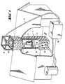
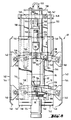
- Fig. 1 shows a schematic representation of a "cut" house with a chimney also shown in section.
- a compressor 10 parked on the floor is connected to a fluid motor 12 which is drained off in the chimney and is designed as a pneumatic motor via a fluid hose 14 which supplies compressed air.
- the fluid motor carries a milling tool 16, which is here formed by chains, e.g. but can also be formed by a suitably designed milling crown.
- the milling tool 16 When the fluid motor 12 is pressurized with the compressed air, the milling tool 16 is set in rotation and thereby mills the chimney to the desired diameter, also with removal of sooting in the inner shell of the chimney and with the removal of protruding wall parts.
- the chimney is continuously milled from bottom to top by slowly pulling up the fluid motor 12 together with the milling tool 16.
- Working from top to bottom is also possible, e.g. with the milling crown mentioned.
- a suction device is introduced, through which the dust that is formed is suctioned off.
- a pressure oil pump 10 can replace the compressor 10 and the pneumatic motor and a hydraulic motor as the fluid motor 12.
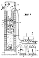
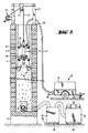
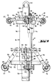
- a chimney 4 here as a house chimney, is erected on a chimney foundation 2 and has an outer chimney construction 6 running all around and an inner shell surrounded by it, which is provided as an inner pipe string 8 carrying flue gas.
- the load-bearing chimney structure 6 is shown here as masonry made of artificial or natural stones and the inner pipe string 8 as a continuous layer, for example made of centrifugal cement. Any other single or multi-layer chimney construction with or without additional intermediate shells, such as thermal insulation layers or vapor diffusion insulation layers, is alternatively possible.
- the inner pipe string can also consist of fireclay or steel pipes and can also consist in the usual way of axially adjoining and mostly sealed by grout or other sealing strands.
- a chimney slide 18 In the area of the lower end of the chimney 4 above the chimney foundation 2 there is an opening with a chimney slide 18 through which soot is usually removed.
- the chimney 4 ends at the top in a frontal plateau 20, on which a chimney head (not shown), in the case of more modern chimneys, possibly via an end plate (not shown), can be placed on the building.
- the chimney 4 is expediently milled out with the chimney head removed and, if appropriate, also with the end plate removed.
- a support frame or support frame 22 is mounted so that it is immovable laterally, for example by Clinging on the upper outer chimney edge.
- the supporting frame 22 carries a roller 24, via which the fluid hose 14 in the arrangement according to FIG. 1 and a pull rope in the arrangement according to FIGS. 2 to 4 26 is performed.
- the fluid motor 12 is suspended here on this traction cable 26, for which purpose the fluid hose 14 itself is used according to FIG. 1. If this fluid hose 14 itself is to take over the traction function, it must be designed to be suitably tensile, for example by a tensile hose reinforcement or hose casing.
- the cable winch 28 or a hose unwinding roller are rigidly attached to the support structure with their shaft during operation, so that the winding forces are absorbed via the support structure at the upper end of the chimney 4.
- the cable winch 28 is expediently adjustable in height.
- the fluid hose 14 is here guided separately from the pull cable 26 from the upper end of the chimney 4 and connected to a compressor (cf. compressor 10 in FIG. 1) outside the chimney, which is driven by an internal combustion engine, expediently a diesel engine. Both the compressor and the internal combustion engine are mounted on a chassis 30 with a parking brake 32 and surrounded by a sound-absorbing hood 34.
- the chassis 30 can on any flat base 36, next to the building in which the chimney 4 is built, set up and braked against this base.
- about two electric motors 46 or, alternatively, compressed air motors can be provided, which can then be appropriately fed by the compressor arranged under the hood 34.
- the two electric motors 46 enable the available drive power to be multiplied correspondingly when supplied by local mains voltage and can thus save a high-voltage connection. If necessary, more than two such motors 46 can also be provided.
- the main separator is designed, for example, as an industrial vacuum cleaner and is connected via the suction lines shown through the opening of the chimney slide 18 to the floor space of the chimney 4 above the chimney foundation 2.
- the milling tool 16 shown in FIG. 2 is described in more detail below with reference to FIG. 14.
- the milling tool 16 used in FIGS. 3 and 4 is described in more detail below with reference to FIG. 15.
- the fluid motor 12 also carries a guide 48, as is described in more detail with reference to FIGS. 9 and 10a to 10d.
- the fluid motor 12 itself has the type described below with reference to FIG. 5, possibly with FIG. 6, which requires guidance.
- the guide 48 is omitted with the basic construction according to FIGS. 2 to 4 remaining the same.
- the flue gas-carrying inner pipe string 8 is milled in one go from bottom to top, in the arrangement according to FIG. 4 also in one go from top to bottom.
- the inner layer 8 interpreted here as inner pipe string 8 could also only be used include an inner zone detected during the milling process, with radially successive zones being able to be removed downwards, upwards, downwards, etc., one after the other, in alternating milling operations.
- Post-processing steps, such as finishing operations can also be carried out by changing the milling tool 16 by means of the same fluid motor 12.
- the milling tool 16 can optionally also be arranged at the top and the fluid motor 12 at the bottom in a manner not shown; however, this presents the difficulty of having to direct the fluid motor through the body of the milling tool when it is supplied from above or, alternatively, of supplying the fluid hose 14 from the start through the opening of the chimney slide 18, or another opening.
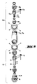
- the pneumatic motor 12 shown in FIG. 5 has a cylinder 50, along the axis of which the rotor 52 of the pneumatic motor 12 extends.
- the cylinder 50 is delimited on the outside and inside by a cylinder surface, but the inner cylinder surface is arranged eccentrically to the outer cylinder surface.
- the cylinder 50 has a correspondingly changing wall thickness.
- the rotor 52 has a cylindrical outer surface which, with the eccentric inner surface of the cylinder 50, delimits a compression space 54 (shown in cross-hatching).
- the rotor 52 is in turn attached to a rotor shaft 56.
- Slits 58 extending tangentially to the rotor shaft 56 are distributed over the circumference of the rotor 52, which is formed from a solid cylinder shell, and extend over the entire axial length of the rotor 52 and end at a radial distance from the rotor shaft 56. In practical embodiments, between four and six such slots are provided, for example. Rotor blades are loosely inserted in the slots. While the fluid motor 12 can otherwise be made of steel, the rotor blades 60 can be made of a suitable plastic, for example of phenoplasts or melanin resins, such as are sold under the protected trade name "Pertinax", for example.
- the rotor lamellae 60 are rectilinear on their longitudinal edge interacting with the cylindrical inner surface of the cylinder 50 and complementary to a corresponding one on their longitudinal edge engaging in the slots Basic design of the slots is flattened to be axially guided in the slots in their radially lowest engagement position.
- the rotor lamellas are pressed outwards into contact with the inner wall surface of the cylinder 50. They divide the compression space 54 into traveling chambers distributed over the circumference of the rotor shaft, short-circuit air between the chambers being largely avoided by sufficiently close contact of the slots on the rotor lamellae.
- two continuous axially parallel bores 62 run alongside one another in the circumferential direction, via which the compressed air supplied by the compressor 10 via a compressed air hose 14 is fed to the compression space 54 via four slots 64.
- the slots 64 extend in the circumferential direction of the cylinder 50 and are arranged in pairs in the vicinity of the two ends of the cylinder.
- Radially through outlet holes 66 are distributed in the sickle of the tapering wall thickness of the cylinder, which decreases in the running direction of the rotor 52, and several, for example five, of these holes are expediently arranged in several, for example two, rows across the axial area between the slots 64 Distributed circumference of the cylinder 50.
- the cylinder 50 is sealed off at both ends by a cover 68.
- Each cover 68 carries on its side facing away from the compression space 54 a ball bearing 71 for the rotor shaft 56, which extends through axial openings in both covers 68 and is secured against axial displacement.
- the rotor shaft 56 is extended beyond the ball bearing 71 as an input shaft of a single-stage reduction gear, here a planetary gear.
- the planetary gear corresponds to the lower half of the exposure drawing according to FIG. 6, in the upper half of which further elements for the two-stage design of the reduction gear are shown, here an axially connected two-stage planetary gear.
- a pinion 70 is seated on the driven end of the rotor shaft outside the cylinder 50.
- This pinion engages in an internal toothing of a planet gear cage 72.
- the planet gears 74 supported in this mesh with a sun gear ring 76.
- This is rigid on the inside of a pot-shaped extension 78 of an output shaft 80 , on which the shaft of the milling tool 16 is coupled in a rotationally fixed manner.
- a second planetary gear stage is arranged axially between the output shaft 80 and the described first stage of the planetary gear, the elements of which in FIG. 6 are identified with the addition a while the functional parts are otherwise the same.
- first stage of the planetary gear is not connected directly to the output shaft 80, but that with an otherwise identical design as the end of the output shaft facing the pneumatic motor, an axially aligned intermediate shaft 82 is used, on which a pinion 70a sits, which corresponds to the pinion 70 in the force introduction function at the input of the first gear stage.
- the entire unit which is described by the cylinder 50 together with covers 68, the rotor shaft 56 mounted therein and the planetary gear (85) (designated as a whole) (85), is surrounded by a two-part solid armored housing 84 on its side facing the suspension and all around , wherein a solid lower end plate 86, which carries a first ball bearing 88 for the output shaft 80 on the inside and is connected tightly to the armor housing 84, closes the housing on the side facing the milling tool 16.
- the output shaft 80 is also supported by a second ball bearing 90, which is fastened to the inside of a first part 92 of the tank housing.
- This first part 92 is arranged in the form of a hood and, starting from the end plate 86, comprises all the above-mentioned parts of the output housing (s) and pneumatic motor, the hood base 94 being opposite the free end 96 of the rotor shaft 56 opposite the output shaft 80.
- the cylinder 50 is provided with a slightly protruding ring flange at each of its two ends, and these ring flanges are tightly fitted into the housing of the first part 92 of the armored housing 84. This creates a certain annular gap between the outer surface of the cylinder 50, the two ring flanges and the inner surface of said first part 92, through which the exhaust air from the compression space 54 emerging from the outlet holes 66 can be freely distributed. This exhaust air can escape radially further outwards through a ring of outlet holes distributed over the wall of the first part 92 in the circumferential direction.
- the compressed air is fed to the pneumatic motor through an inlet nozzle 100 projecting axially upwards, which is integrally formed in the hood bottom 94. From there, the compressed air reaches the bores 62 via the free space 102 formed below the hood base 94 within the first part 92 and from there finally into the compression space 54 in the manner described.
- the second part 104 is screwed around the outside on the side of the suspension of the fluid motor. As will be described later with reference to FIG. 9, the entire unit of fluid motor 12 and milling tool 16 is suspended from this second part 104.
- the second part 104 surrounds the first part 92 of the armor housing 84 to below the exit holes 98 and is screwed into a recess on the first part such that both parts 92 and 104 of the armor housing 84 have a common, small-diameter cylindrical outer surface.
- annular gap 106 is formed in the overlapping area between the two parts 92 and 104 of the armor housing 84, which lies opposite the exit holes 98 and is sealed in the area of the joint located underneath between the two parts of the armor housing.
- the annular space 106 is extended radially inward in relation to the outer end face of the hood base 94 by an annular gap 108 between the outer end face of the hood base 94 and a massive continuation part 110 of the second part 104 which leads axially upward.
- a radial bore 112 is first formed, which extends outside the tank housing with an inlet connection piece extending axially next to it leads to the connection with the compressed air hose 14. This connection bore 112 is sealed off from the outer end of the inlet connector 100 on the hood base 94.
- the annular gap 108 communicates with axially and radially extending bores 105 and 107 in the continuation part 110 of the second part 104 of the armored housing 84, in order to finally exhaust the air from the pneumatic motor through an exhaust shaft 114 attached to the side of the armored housing, and during milling to escape into the interior of the chimney.
- the exit direction of this exhaust shaft is chosen axially parallel to the milling tool 16.
- the exhaust air escaping only over a portion of the circumference of the armor housing is distributed as a jacket flow in such a way that not only blowing on the milling tool is possible, but also a barrier against the rising of milling dust over the entire circumference of the armor housing.
- the pneumatic motor according to FIG. 7 can basically be constructed in the same way, without prejudice to the graphic deviations in FIG. 7.
- the torque transmission from the pneumatic motor to the milling tool takes place here in the absence of a reduction gear in the ratio 1: 1, i.e. directly.
- the free end of the rotor shaft 56 protruding from the cylinder 50 on the milling tool 16 side is connected to an output shaft 115, which corresponds to the output shaft 80 according to FIG. 5, via a striking mechanism 117.
- This converts the continuous rotary movement of the rotor shaft 56 into a rotary impact movement with impact action in the angular direction due to one per revolution of the Rotor shaft effective interaction of a so-called hammer and a so-called anvil of the striking tool.
- An axial oscillation of the milling tool 116 can be dispensed with entirely if an axial component could also be included if necessary.
- An essential feature of switching on such a striking mechanism is to compensate for a counter torque occurring when the milling tool 16 is working - an elastic hammer blow between the hammer and anvil of the striking mechanism per revolution - by the impact of the impact in the striking mechanism.
- the output shaft 115 is hollow, with a polygonal inner cross section, in particular as a hexagon. This allows marketable Milling tools, which are generally provided with a hexagon connection, can be simply plugged in while transferring very high torques.
- a corresponding plug-in piece 118 of a milling tool 16 is shown in FIG. 7.
- the bore of the hollow output shaft 115 can also be used as a supply channel for control fluid, in particular compressed air, for the milling tool.
- a control line connection 120 is led out at the milling-side end of the hollow shaft, for example in order to reverse a milling tool which can be reversed for working directions upwards and downwards when the working direction changes.
- FIG. 8 and 9 to 11 show two possible preferred construction types of positive guides which can be used in the construction of a pneumatic motor according to FIG. 6 which requires torque support. Both types are characterized by a relatively little covered viewing gap between the tank housing 84 and the inner surface of the chimney 4.
- connection coupling 124 here a so-called socket, for connecting the output shaft 80 according to FIG. 5 to the milling tool 16.
- an eyelet 122 is provided at the upper end on the second part 104 of the tank housing, on which the Pull rope 26 can be latched.
- the connecting piece 126 which is arranged here laterally on the tank housing and communicates with the connecting bore 112, on the fluid motor analogously to the eyelet 122 in a manner not shown and train to transmit force, ie with connecting means to the reinforcement or tensile casing of the fluid hose 14.
- a retaining washer 128 is arranged with sufficient axial spacing for guidance in the area of both ends of the armor housing 84 (see in particular also FIGS. 10a and 10b, in which the retaining washer 128 in plan view and in Side view is shown).
- the retaining washer is clamped along the action line 130 shown in dashed lines in FIG. 10a by means of tensioning screws 132 on the outer circumference of the armored housing 84.
- the dashed double line 134 in FIG. 10 a describes in the large square cross section of the holding disks 128 in the area of the center of the boundary lines of the square a pivot axis 134 for swivel arms 136.
- These are straight levers, one end of which in the area of the axis 134 on a pivot pin 138 on the armored housing 84 is articulated and the other end is articulated to a cheek 140 on the radially inner side of a runner 142.
- four runners 142 are distributed over the circumference of the pneumatic motor. These have an elongated, at least approximately rectilinear central section 144 and, at the top and bottom, ends 146 which are each curved inwards or at an angle.
- the outer surface of the armor housing 84, the runners and the two swivel arms articulating the respective runners above and below form a parallel guide linkage.
- All four parallel guide rods are radial in their axially displaceable actuating plate 147 Width adjusted together.
- the circumference of the actuating plate in the region of a linkage 148 is connected to a linkage 152 in the central region of the respective upper swivel arm 136 via a pull lever 150 which extends along the outside of the tank housing.
- the actuating plate 147 is axially displaceably guided on two diagonally opposite guide rods 154.
- the guide rods in turn are screwed with their lower ends into the upper holding disk 128 and connected at their upper ends by a transverse yoke 156 to which the eyelet 122 is welded.
- the actuating plate 147 lies in its lowest position due to the weight of the rods with runners articulated on it.
- a pneumatically actuated servo cylinder 158 is used to lift the actuating plate 147, which is fastened to the end face of the armor housing 84 and can be loosely supported with its stamp 160 at the axial center of the actuating plate.
- a fastening 162 at the point of attack on the actuating plate 147 is preferred.
- the holding disk 128 is bevelled at the corners of its large square floor plan, and in each of the corners a radially extending incision 163 is provided, which in the area of the line of action 130 for tightening on the circumference of the Armor housing is formed as a continuous slot as in the above-described embodiment.
- the free end of the lever is formed with a one-sided projection as fork 169, a shaft 172 being arranged on the two arms 170 of fork 169, on each of which a cutting wheel 174, or alternatively a roller or roller, is rotatably mounted.
- An elastic, flexible buffer element in the form of a circumferential cellular rubber ring 176 is secured against the axial displacement, under which the central area of the respective lever lies loosely to limit its downward pivoting position. If necessary, the axial position of this buffer element 176 can also be adjusted. With the appropriate setting, it is also possible to choose the same or desired different radial exposure (for example in adaptation to the conical shape of the chimney) with different lengths of the levers 164. In this sense, the upper levers 164 are drawn with a shorter length than the lower levers 164. The somewhat further radial projection of the lower levers 164, which can also be seen in FIG.
- a notch 178 can be seen in FIG. 9 on the outer circumference of the armored cylinder. This notch 178 is opposite a corresponding parallel notch on the covered other side. As a result, the two parts 92 and 104 of the armor housing 84 can be screwed on with a tool by applying a sufficient torque.
- the guide rods 154 of the embodiment according to FIG. 8 are replaced here by a connecting pin 180 which is fixed at the top by the eyelet 122 and is rigidly connected to the end face of the armored housing 84 at the bottom.
- the connecting pin 180 a solid cylinder, with a smaller diameter than the armored housing 84.
- This has the advantage of being able to arrange the upper levers 164 with a particularly small radial projection. Because of the greater load on the lower levers, the problem does not arise to such an extent. All in all, this has the possibility of adapting to particularly small clear chimney widths.
- Fig. 11 shows a simple modification with which the same structure of the guide can be designed double-acting, with a constant geometry without the need for conversion work.
- the levers which are arranged in the form of a ring at the top and bottom, are connected to one another by tension elements 182 which extend along the armor housing 84 and which are expediently tension springs.
- tension elements 182 which extend along the armor housing 84 and which are expediently tension springs.
- the milling tool has a central support body 192 around which milling-effective elements held by the support body extend.
- the upper end of the support body is shown here as a square, with hexagons instead being provided in the case of a design which complies with the standards.
- These are rigidly attached to the output shaft of the respective fluid motor 12 in axial alignment with its effective axis via fastening pins 194 which engage in corresponding fastening bores in the support body 192.
- fastening pins 194 which engage in corresponding fastening bores in the support body 192.
- the support body 192 extends with a constant cross section over the entire axial height of the milling element.
- the lower end is formed as a support 196 which is fastened axially immovably to the support body 192 via a fastening pin 194.
- spacer sleeves 198 and spacers 200 are loosely attached to the support body.
- the spacers 200 are preferably arranged equidistantly, in which case the spacer sleeves 198 arranged between them each have the same axial length or can each be of the same design.
- the bottom spacer sleeve 198 can be made shorter, as shown. Alternatively, you can do without them entirely and place the lowest spacer directly on the support 196.
- each spacer disk has a single chain link 202 distributed around the circumference of the milling tool, each chain link 202 carrying a milling disk 204 at its outer end.
- FIG. 12 an illustration is drawn in FIG. 12, in which the rotational state of the milling tool is assumed, so that the outer chain links 202, which are connected in a chain-like manner to both the spacer disks 200 and the milling disks 204, fly horizontally outward, as is also the case in FIG. 1 for longer chain-like Milling tools is shown.
- the idle state such chains hang down under their own weight so that they can then easily be passed through areas of the chimney that have not yet been milled out.
- the milling disks 204 describe an active cone which initially widens conically from top to bottom and then tapers again conically, and which is axially symmetrical with respect to the middle spacer disk 200a in order to be able to mill equally effectively both upwards and downwards with the same geometry. Since the milling disks of the middle spacer 200a are subjected to the greatest stress due to their largest radial projection and should therefore be chosen to be particularly robust in each case, it is also advisable, as shown, to make the middle spacer 200a stronger than the other spacers (with the same Material with greater thickness). The spacers have different radial widths corresponding to the respective radial radius of the active cone at the point in question, while the individual chain links 202 can all be selected in the same way.
- the support body 192 is, as mentioned with regard to the milling tool described above, provided with a lower support, not shown, analogous to the support 196, on which a single elongated spacer sleeve 198a rests (instead of the majority of the spacer sleeves) 198 and spacers 200 of the previously described embodiment).
- support plate 206 is arranged, which is square here.
- a radially extending slot 208 is formed in each of the four corner regions of this square support plate 206, in each of which a set screw 210 engages from the sides facing away from the spacer sleeve 198a.
- a set screw 210 engages from the sides facing away from the spacer sleeve 198a.
- four bow-shaped milling blades 212 can be pivoted out over the circumference of the milling tool, but can also be fixed in a specific angular position when the set screws 210 are tightened.
- the milling blades 212 can be freely axially displaced along the elongated holes 208, this displaceability also being excluded when the adjusting screw is tightened.
- the milling tools each have a cutting edge 214 on at least one outer narrow side. It is also conceivable to provide a cutting edge 214 on both edges of the milling lamella, although only one cutting edge is used in one working direction, be it for working under different operating conditions, be it for reverse assembly for subsequent wear of both cutting edges.
- the cross section of the milling lamella 212 can also be selected such that a cutting edge 214 is only possible on one edge.
- the cutting edges 214 are also radially axially from top to bottom issued on the outside to describe a conical knitting cone again. If the working direction is reversed, this workpiece can also be repositioned by exchanging the legs of the bow-shaped milling blades, on which the set screws 210 engage between the support plates 206.
- this workpiece can also choose to issue the milling lamella itself in the manner of a double cone, as has already been described with regard to the embodiment according to FIG. Here the double cone would then be formed by the same milling element.
- articulations of the bow-shaped milling lamellae can also be provided simply via individual chain links, as is the case in the embodiment according to FIG. 12 with regard to the connection of the spacer disks 200 there with the outer milling disks 204 on the basis of the individual ones Chain links 202 is described.
- a support disk 216 is fastened to the lower end of the support body 192 in a manner similar to the previously described support 196, for example by means of a fastening screw, not shown, with which the support disk 216 is attached to the form-fitting from below is partially screwed into the support body 216 engaging support body 216.
- Each rectangular groove 218 which are equidistant in the circumferential direction and which run axially are distributed over the circumference of the support disk 216.
- an oscillating block 220 which forms a straight, short lever and essentially occupies the width of the rectangular groove with relative mobility, is articulated on a bearing pin 222 so as to be oscillatable.
- the bearing pin 222 is driven in with a form fit by means of through bores 224 opposite each other on the respective rectangular groove 218.
- the oscillating blocks are essentially flush with the upper end face of the support disk 216.
- the upper ends of the oscillating blocks 220 are also beveled at least on their radially inner side of the milling head.
- a roof 226 of the same type inside and outside is shown with a flat ridge design.
- the ridge is essentially flush with the surface of the support plate 216 after the pivoting position of the oscillating block 220, while the radially inner roof slope 228 strikes the base of the rectangular groove 218 at a predetermined pivoting position of the oscillating block 220 and thus limits the pivoting out.
- the double-sided roof design can be used to reverse the direction of installation if the vibrating block wears on one side.
- a threaded bore 230 is recessed.
- a high stress-absorbing stud 232 is screwed in, which, with a little radial play, serves as a bearing shaft for a cylindrical shell-shaped base body 234 of a milling head 236.
- the milling head is complemented by milling pins 238, which fit into the cylindrical circumferential surface of the base body 234 are rigidly embedded and protrude radially from this peripheral surface, so that the base body and burrs together form a kind of radial hedgehog.
- the burrs have the same length, so that the peripheral surface of the hedgehog describes a cylindrical, but possibly also a different envelope surface, for example an envelope surface slightly bulged in the middle axial length.
- the pins themselves are straight and made of hard metal, for example a steel alloy or other hard metals or hard metal alloys.
- the receiving holes of these rows are offset from one another with a gap, the rows being arranged equidistantly.
- the head of the respective stud 232 is embedded in the base body on its outer end face.
- this tool can be used with the same geometry working both downwards and upwards, with a support body 192 then optionally being provided on both end faces the support disc 216 provides.
- a support body 192 then optionally being provided on both end faces the support disc 216 provides.
- the oscillating blocks 220 which act as straight oscillating arms, can still hang vertically downwards somewhat freely, if the milling tool is not set in rotation. Then the outer enveloping surfaces of the three milling heads 236 are supported against one another in such a way that all three milling heads are essentially axially aligned, so that insertion into a chimney cross-section which has not yet been milled is conveniently possible.
- the vibrating blocks can also be brought into contact with their internal longitudinal surface at the bottom of the rectangular groove 218 in this operating mode. You can also design the bottom of the "rectangle" groove bulged, in order to hold the vibrating block axially if necessary.
- the embodiment shown does not permit a double-acting operation in terms of its geometry without repositioning a support body 192 provided on both sides when attaching it to the output shaft of the fluid motor 12.
- the stop of the oscillating block 220 on the bottom of the rectangular groove 218 can be made detachable by means of a servo device such that the oscillating block is pivoted out of the hanging arrangement according to FIG. 5 into an essentially standing arrangement and there also by an outside, also servo-adjustable support is fixed.
- a servo control can in turn be carried out by means of the same equipment which is used for the operation of the fluid motor 12, but via a separate control line.
- Such a striking mechanism can also be arranged at a different location, in particular between the fluid motor and its suspension, it is described below in a direct connection after the rotor of the fluid motor. In this respect it replaces a separate reduction gear, in which the torque amplification of a reduction gear is exchanged for an increase in effectiveness by hammering.
- a separate reduction gear in which the torque amplification of a reduction gear is exchanged for an increase in effectiveness by hammering.
- a hammer carrier 242 of the striking mechanism is driven with a ratio of 1: 1 by the rotor 52 of the pneumatic motor.
- Two hammers 246 and two hammer pins 244 are loosely arranged in the hammer carrier 242 at diametrically opposite circumferential locations, the hammer pins 244 as end stops limiting a movement of the hammers 246 radially outwards under the centrifugal force.
- the hammers 246 are carried in the direction of rotation.
- the arrangement of the hammers 246 in the hammer carrier 242 is designed differently, which manifests itself in different circumferential lengths of the circumferential grooves to be accommodated and their different geometries.
- the hammers 246 make a wobbling movement.
- the hammers 246 interact in the direction of rotation with an anvil 248, which forms a non-rotatable, preferably rigid, unit with the output shaft 80 carrying the milling tool 16.
- the anvil 248 is supported in the impact tool housing 250 via the bearing bush 252.
- the output shaft 80 is thus also given a uniform mounting.
Landscapes
- Engineering & Computer Science (AREA)
- Mechanical Engineering (AREA)
- Mining & Mineral Resources (AREA)
- General Engineering & Computer Science (AREA)
- Working Measures On Existing Buildindgs (AREA)
- Finish Polishing, Edge Sharpening, And Grinding By Specific Grinding Devices (AREA)
- Milling Processes (AREA)
- Structures Of Non-Positive Displacement Pumps (AREA)
- Drilling And Boring (AREA)
Claims (22)
- Dispositif pour fraiser l'intérieur d'une cheminée (4) à chemiser intérieurement, comportanta. une unité de travail (12, 16) qui comprend un moteur d'entraînement (12) et un outil de fraisage (16) entraîné par celui-ci, et qui est conçue de manière que du matériau de construction de la paroi de la cheminée (4) puisse être éliminé par fraisage ;b. une source de puissance (10) pouvant être disposée à l'extérieur de la cheminée (4) et destinée au moteur d'entraînement (12) ;c. un dispositif de suspension (14, 26) pour l'unité de travail (12, 16), à l'aide duquel l'unité de travail (12, 16) peut être déplacée vers le haut et vers le bas dans la cheminée (4) ;d. une conduite de transmission de puissance (14) permettant la transmission de la puissance d'entraînement de la source de puissance (10) au moteur d'entraînement (12) ;e. un dispositif de guidage coopérant avec la surface intérieure de la cheminée (4), destiné au mouvement de soulèvement et/ou d'abaissement de l'unité de travail (12, 16) et comportant des éléments de guidage et d'appui dont les distances radiales à l'axe-moteur du moteur d'entraînement (12) sont variables, caractérisé en ce quef. le moteur d'entraînement est un moteur à fluide (12) ;g. la source de puissance est une source de fluide (10) ;h. la conduite de transmission de puissances est un tuyau de fluide (14), eti. le moteur à fluide (12) comporte en tant qu'éléments de guidage et d'appui des patins (142) s'étendant sur la périphérie du moteur à fluide (12) et le long de l'axe du moteur à fluide (12).
- Dispositif selon la revendication 1, caractérisé en ce que le moteur à fluide (12) est un moteur pneumatique, le tuyau de fluide (14) une conduite d'air comprimé, et la source de fluide (10) un compresseur.
- Dispositif selon la revendication 2, caractérisé en ce que l'échappement d'air (114) du moteur pneumatique (12) est agencé sur l'unité de travail (12, 16).
- Dispositif selon la revendication 3, caractérisé en ce que l'échappement d'air (114) est dirigé vers le bas en direction de l'outil de fraisage (16).
- Dispositif selon l'une des revendications 1 à 4, caractérisé en ce que l'unité de travail (12, 16) constituée du moteur à fluide (12) et de l'outil de fraisage (16) est suspendue à un élément étant uniquement un élément de traction (14 ; 26).
- Dispositif selon la revendication 5, caractérisé en ce que l'unité de travail (12, 16) est suspendue au tuyau de fluide (14).
- Dispositif selon l'une des revendications 1 à 6, caractérisé en ce que le moteur à fluide (12) comporte en tant qu'éléments de guidage et d'appui des patins (142) s'étendant sur la périphérie du moteur à fluide (12) et le long de l'axe du moteur à fluide (12) la distance des patins (142) à l'axe du moteur à fluide (12) est réglable.
- Dispositif selon la revendication 7, caractérisé par une commande par fluide, de préférence pneumatique, pour le réglage des patins (142).
- Dispositif selon l'une des revendications 1 à 8, caractérisé en ce que le rotor du moteur à fluide (12) est relié à l'outil de fraisage (16) par l'intermédiaire d'un réducteur (85, 85a).
- Dispositif selon la revendication 9, caractérisé en ce que le réducteur (85, 85a) est à plusieurs rapports.
- Dispositif selon la revendication 9 ou 10, caractérisé en ce que ledit réducteur (85, 85a) est réalisé sous la forme d'un train épicycloïdal.
- Dispositif selon l'une des revendications 1 à 11, caractérisé en ce que les patins (142) du moteur à fluide (12) sont à double effet, c'est-à-dire sont réalisés de manière à effectuer un guidage aussi bien vers le haut que vers le bas.
- Dispositif selon l'une des revendications 1 à 12, caractérisé en ce qu'entre le moteur à fluide (12) et l'outil de fraisage (16) est intercalé un mécanisme à percussion (117) agissant en direction angulaire.
- Dispositif selon la revendication 13, caractérisé en ce que le mécanisme à percussion (117) est réalisé sous la forme d'une pièce axiale de prolongement, amovible, et est disposé, le cas échéant, entre le moteur à fluide (12) et un réducteur (85, 85a).
- Dispositif selon la revendication 13 ou 14, caractérisé en ce que le moteur à fluide (12) est relié selon un rapport 1:1 au mécanisme à percussion (117) et celui-ci est relié à l'outil de fraisage (16) selon un rapport 1:1.
- Dispositif selon l'une des revendications 13 à 15, caractérisé par un dispositif de commande qui met en route automatiquement le mécanisme de percussion (117), uniquement à une vitesse de rotation limite de l'outil de fraisage, de par exemple 2 500 tr/min.
- Dispositif selon l'une des revendications 1 à 16, caractérisé en ce qu'entre le moteur à fluide (12) et sa suspension (14 ; 26) est agencé un mécanisme à percussion de compensation.
- Dispositif selon l'une des revendications 1 à 17, caractérisé en ce que l'accouplement entre le moteur à fluide (12) et l'outil de fraisage (16) est réalisé sous la forme d'un raccord rapide.
- Utilisation du dispositif selon l'une des revendications 1 à 18 pour le fraisage intérieur en un seul passage de longueurs de cheminée de plus de 15 m, par exemple d'immeubles d'au moins trois étages ou de cheminées d'usine complètes.
- Utilisation du dispositif selon l'une des revendications 1 à 18 dans des cheminées à axe courbe.
- Utilisation du dispositif selon l'une des revendications 1 à 18 dans des cheminées devant subir un fraisage intérieur, présentant un diamétre nominal de 140 mm ou moins (plus petit diamètre dans le cas de cheminées non circulaires) de leur section transversale intérieure.
- Utilisation selon la revendication 21 avec comme condition que le diamètre nominal est au plus égal à 100 mm.
Priority Applications (2)
| Application Number | Priority Date | Filing Date | Title |
|---|---|---|---|
| AT89104394T ATE83305T1 (de) | 1988-03-12 | 1989-03-13 | Vorrichtung zum ausfraesen eines auszufuetternden schornsteins sowie anwendungen. |
| DD33864990A DD297866A5 (de) | 1989-03-13 | 1990-03-13 | Verfahren und vorrichtung zum spanabhebenden erweitern, insbesondere zum ausfraesen, eines auszufuetternden schornsteins sowie anwendungen |
Applications Claiming Priority (2)
| Application Number | Priority Date | Filing Date | Title |
|---|---|---|---|
| DE3808376A DE3808376A1 (de) | 1988-03-12 | 1988-03-12 | Vorrichtung zum ausfraesen eines auszufuetternden schornsteins |
| DE3808376 | 1988-03-12 |
Publications (4)
| Publication Number | Publication Date |
|---|---|
| EP0341394A2 EP0341394A2 (fr) | 1989-11-15 |
| EP0341394A3 EP0341394A3 (en) | 1990-01-31 |
| EP0341394B1 EP0341394B1 (fr) | 1992-12-09 |
| EP0341394B2 true EP0341394B2 (fr) | 1995-09-13 |
Family
ID=6349637
Family Applications (1)
| Application Number | Title | Priority Date | Filing Date |
|---|---|---|---|
| EP89104394A Expired - Lifetime EP0341394B2 (fr) | 1988-03-12 | 1989-03-13 | Dispositif pour élargir une cheminée à revêtir intérieurement par fraisage, ainsi que des applications |
Country Status (7)
| Country | Link |
|---|---|
| US (1) | US5096262A (fr) |
| EP (1) | EP0341394B2 (fr) |
| AT (1) | ATE83305T1 (fr) |
| DE (3) | DE3808376A1 (fr) |
| HU (1) | HU208574B (fr) |
| RU (1) | RU2071580C1 (fr) |
| WO (1) | WO1989008802A2 (fr) |
Families Citing this family (20)
| Publication number | Priority date | Publication date | Assignee | Title |
|---|---|---|---|---|
| AT27U1 (de) * | 1991-06-06 | 1994-10-25 | Kuny Kaminbau Ing Fritz Baum & | Vorrichtung zum aufweiten von schächten |
| DE4227309A1 (de) * | 1992-08-18 | 1994-02-24 | Harm Willem Holman | Verfahren zur Vorbereitung der Demolierung bzw. Zerstörung von Gebäuden und dergleichen und Vorrichtung zur Anwendung des Verfahrens |
| DE19534794C1 (de) * | 1995-07-30 | 1997-01-16 | Jaeger Und Peters Schornsteint | Vorrichtung zum Fräsen von Schornsteinen mit Fräswerkzeug |
| US5555939A (en) * | 1995-10-27 | 1996-09-17 | Berger; Martin T. | Apparatus for extinguishing chimney fires |
| US5992778A (en) * | 1998-07-31 | 1999-11-30 | Martin Engineering Company | Cutting member for a cleaning apparatus used to dislodge adherent bulk material in a storage container |
| DE19948683C2 (de) * | 1998-09-30 | 2002-11-07 | Varioclean Lueftungsanlagenrei | Verfahren zur Sanierung von Abluftanlagen im Wohnbereich |
| NO328188B1 (no) * | 2008-03-11 | 2010-01-04 | Qsst As | Anordning og femgangsmåte for fjerning av avleiring i en borehullsinstallasjon |
| US8245779B2 (en) * | 2009-08-07 | 2012-08-21 | Geodaq, Inc. | Centralizer apparatus |
| US8794712B2 (en) * | 2010-10-13 | 2014-08-05 | Gerard J. MacNeil | Refractory material removal system and method |
| US20130220381A1 (en) * | 2010-10-13 | 2013-08-29 | Gerard J. MacNeil | Lining material removal system and method |
| ITVI20130236A1 (it) * | 2013-09-26 | 2015-03-27 | Mpr S R L | Dispositivo di ingrassaggio |
| NL2014360B1 (nl) * | 2015-02-26 | 2016-10-13 | Van Manen Gerrit | Schoorsteenboor met geleiding. |
| US10562081B2 (en) * | 2015-10-08 | 2020-02-18 | Pneumat Systems, Inc. | Counter-rotational dual whip-head device for fragmenting solidified bulk materials in containment vessels |
| MX2018012865A (es) * | 2016-04-19 | 2019-08-22 | Ecolab Usa Inc | Dispositivo de limpieza para el sistema de transporte neumatico. |
| WO2018187290A1 (fr) * | 2017-04-03 | 2018-10-11 | Micronova Manufacturing, Inc. | Configuration de balai-éponge plan à espacement réglable |
| CN110216591B (zh) * | 2019-05-29 | 2020-04-21 | 大庆华油石油科技开发有限公司 | 一种具有收放装置垂直管道喷砂器 |
| US20210102699A1 (en) * | 2019-10-04 | 2021-04-08 | ChimSteam, LLC | Method and Apparatus for Cleaning Chimneys |
| CN111298925B (zh) * | 2020-03-03 | 2022-04-08 | 许婷婷 | 一种工业用除尘装置 |
| CN111472518B (zh) * | 2020-04-14 | 2021-04-20 | 湖北工业大学 | 一种环保型建筑设计用烟道结构 |
| CN111808620B (zh) * | 2020-06-30 | 2021-08-17 | 安徽创能环保材料有限公司 | 煤热解废弃物的回收利用装置及其方法 |
Family Cites Families (38)
| Publication number | Priority date | Publication date | Assignee | Title |
|---|---|---|---|---|
| DE274605C (fr) * | ||||
| US1293777A (en) * | 1918-11-04 | 1919-02-11 | William J Hogue | Oil-well-cleaning appliance. |
| US1558596A (en) * | 1922-10-02 | 1925-10-27 | Gauntlett & Company Inc | Centrifugal reamer for oil wells and the like |
| FR569632A (fr) * | 1923-08-09 | 1924-04-15 | Appareil permettant le nettoyage intérieur des tuyaux sans les déplacer | |
| US1592268A (en) * | 1923-11-01 | 1926-07-13 | Frank F Hill | Well reamer |
| US1569203A (en) * | 1923-11-21 | 1926-01-12 | Marland Refining Company | Scraping device |
| US1899727A (en) * | 1930-08-08 | 1933-02-28 | Sandstone Harvey David | Combination cutting drill and reaming bit |
| US2095725A (en) * | 1934-07-12 | 1937-10-12 | Standard Oil Co | Tube cleaner |
| US2232018A (en) * | 1937-12-04 | 1941-02-18 | Lon D Wright | Safety device for an apparatus for cleaning water mains |
| US2175406A (en) * | 1938-08-31 | 1939-10-10 | William D Osborn | Chain-head, descaling auger |
| US2275939A (en) * | 1941-03-04 | 1942-03-10 | Baker Oil Tools Inc | Casing scraper |
| US2497659A (en) * | 1944-10-21 | 1950-02-14 | Thomas J Davis | Tubing cleaning device |
| US2641791A (en) * | 1949-06-21 | 1953-06-16 | Harold W Wells | Air-operated apparatus for removing dust accumulations from regenerative checkerwork |
| US2937008A (en) * | 1955-09-30 | 1960-05-17 | Whittle Frank | High-speed turbo-drill with reduction gearing |
| US2889612A (en) * | 1957-09-23 | 1959-06-09 | Joosepson Aser | Semi-automatic roto scaler |
| AT203707B (de) * | 1957-12-13 | 1959-06-10 | Konrad Maly | Vorrichtung zum Regulieren und Erweitern von Kaminen, Rauchfängen od. dgl. |
| DE1229230B (de) * | 1958-03-25 | 1966-11-24 | Hildegard Maly Geb Hartmann | Vorrichtung zum Reinigen und Erweitern von Kaminschlaeuchen |
| DE1175379B (de) * | 1963-05-17 | 1964-08-06 | Hans Woehler | Schornstein-Reinigungsgeraet |
| CH490900A (de) * | 1967-06-28 | 1970-05-31 | Arx Paul Von | Vorrichtung, mit deren Hilfe die Innenwand eines Rohres gereinigt und/oder mit einem Schutzanstrich versehen werden kann |
| US3480092A (en) * | 1967-11-08 | 1969-11-25 | Bell Telephone Labor Inc | Rotary impact burrowing device |
| US3562836A (en) * | 1968-12-30 | 1971-02-16 | Raymond M Bremner | Reaming tool |
| DE2064410A1 (de) * | 1969-12-31 | 1971-07-08 | Astrom, Nils Osten, Valhngby (Schweden) | Vorrichtung zum Beseitigen von Ver stopfungen in Rohrleitungen und zum Reim gen von Rohrleitungen, insbesondere Ab gasleitungen |
| US3669199A (en) * | 1970-03-19 | 1972-06-13 | Youngstown Sheet And Tube Co | Drilling apparatus |
| AT325290B (de) * | 1973-09-18 | 1975-10-10 | Baum Fritz | Vorrichtung zum regulieren und erweitern der innenfläche eines rauchfanges od.dgl. |
| US4222445A (en) * | 1979-01-08 | 1980-09-16 | Vadetsky Jury V | Reduction unit of drilling motor |
| DE2953685A1 (en) * | 1979-05-25 | 1982-01-28 | J Andreasen | Unit for the cleaning of shafts(chutes) |
| DE3009013A1 (de) * | 1980-03-08 | 1981-09-17 | Westendorf, Hubert, 5000 Köln | Vorrichtung zum reinigen von schaechten |
| DE3015381A1 (de) * | 1980-04-22 | 1981-10-29 | Rilco Maschinenfabrik Gmbh & Co Kg, 7401 Dusslingen | Erdbohrvorrichtung |
| CS232019B1 (cs) * | 1982-04-16 | 1985-01-16 | Frantisek Jirik | Zařízení pro frézování komínových průduchů |
| US4678045A (en) * | 1983-07-18 | 1987-07-07 | Lyons William C | Turbine tool |
| US4509701A (en) * | 1983-08-19 | 1985-04-09 | Northern Vibrator Manufacturing Limited | Apparatus for breaking up solidified material in a storage container |
| US4520524A (en) * | 1984-03-26 | 1985-06-04 | Long Jr Charles A | Remotely controlled hydraulic cleaner apparatus |
| DK296584D0 (da) * | 1984-06-18 | 1984-06-18 | Leo Blicher Hansen | Vaerktoej til rensning af skorstene og lignende |
| US4603747A (en) * | 1985-02-14 | 1986-08-05 | Golden James M | Apparatus for removing internal tiles from chimneys |
| DE8626492U1 (de) * | 1986-10-03 | 1987-05-21 | Zellner, Siegfried, 8301 Laberweinting | Vorrichtung zum nachträglichen Vergrößern des Kaminquerschnittes |
| DE8701745U1 (de) * | 1987-02-05 | 1987-03-19 | Fa. Ursula Schiedel, St. Veit, Glaan | Kaminrohrstrang |
| DD262073A1 (de) * | 1987-07-07 | 1988-11-16 | Bauwesen Ingbuero Veb | Schornsteinreinigungsgeraet |
| DD262467A1 (de) * | 1987-07-13 | 1988-11-30 | Max Reinhardt Fa | Verfahren zur sanierung lotrechter schaechte, insbesondere von montageschornsteinen |
-
1988
- 1988-03-12 DE DE3808376A patent/DE3808376A1/de not_active Withdrawn
-
1989
- 1989-03-13 DE DE8989104394T patent/DE58902935D1/de not_active Expired - Lifetime
- 1989-03-13 WO PCT/EP1989/000265 patent/WO1989008802A2/fr not_active Ceased
- 1989-03-13 US US07/457,804 patent/US5096262A/en not_active Expired - Fee Related
- 1989-03-13 HU HU891823A patent/HU208574B/hu unknown
- 1989-03-13 DE DE8903096U patent/DE8903096U1/de not_active Expired
- 1989-03-13 AT AT89104394T patent/ATE83305T1/de not_active IP Right Cessation
- 1989-03-13 RU SU894742558A patent/RU2071580C1/ru active
- 1989-03-13 EP EP89104394A patent/EP0341394B2/fr not_active Expired - Lifetime
Also Published As
| Publication number | Publication date |
|---|---|
| RU2071580C1 (ru) | 1997-01-10 |
| DE8903096U1 (de) | 1989-10-26 |
| EP0341394B1 (fr) | 1992-12-09 |
| DE3808376A1 (de) | 1989-09-28 |
| HU891823D0 (en) | 1991-04-29 |
| WO1989008802A3 (fr) | 1989-12-28 |
| HU208574B (en) | 1993-11-29 |
| EP0341394A2 (fr) | 1989-11-15 |
| WO1989008802A2 (fr) | 1989-09-21 |
| ATE83305T1 (de) | 1992-12-15 |
| HUT55898A (en) | 1991-06-28 |
| EP0341394A3 (en) | 1990-01-31 |
| DE58902935D1 (de) | 1993-01-21 |
| US5096262A (en) | 1992-03-17 |
Similar Documents
| Publication | Publication Date | Title |
|---|---|---|
| EP0341394B2 (fr) | Dispositif pour élargir une cheminée à revêtir intérieurement par fraisage, ainsi que des applications | |
| DE102012008252A1 (de) | Fräsereinrichtung für eine Bodenfräsmaschine, Fräswalze für eine solche Fräseinrichtung und Bodenfräsmaschine mit einer solchen Fräseinrichtung | |
| EP0785054A1 (fr) | Machine à scier des parois et lame de scie | |
| EP3662119A1 (fr) | Étai de coffrage, dispositif d'étai de coffrage et procédé de décoffrage d'un ensemble coffrage | |
| EP0142529B1 (fr) | Echafaudage a progression par moteur pour batiments | |
| WO2014207216A1 (fr) | Dispositif de nettoyage de façades | |
| DE19609899A1 (de) | Vorrichtung zur Herstellung eines Erdlochs | |
| WO2004083561A1 (fr) | Dispositif et procede pour demolir des batiments | |
| DE102009000441B4 (de) | Pendelmühle | |
| DD297866A5 (de) | Verfahren und vorrichtung zum spanabhebenden erweitern, insbesondere zum ausfraesen, eines auszufuetternden schornsteins sowie anwendungen | |
| DE102005032124A1 (de) | Bearbeitungskabine | |
| WO2022003121A1 (fr) | Plate-forme de travail pour fours | |
| EP4112816A1 (fr) | Appareil d'excavation de tranchées pour parois moulées et procédé d'excavation d'une paroi moulée dans le sol | |
| DE19614783C2 (de) | Vorrichtung und Verfahren zum Schichtabtrag annähernd lotrechter Innenwandflächen | |
| DE102004025567A1 (de) | Straßenfräse | |
| DE202011105240U1 (de) | Vorrichtung für die Anwendung im Trockenbohrverfahren zur Minimierung der Faser- und Partikelemissionen | |
| AT393315B (de) | Einrichtung zur bearbeitung einer kanalinnenwand | |
| EP0396747A1 (fr) | Dispositif de prehension de tuyau pour rotor d'installation de forage | |
| DE3842376C2 (de) | Bohrwerkzeug zum Aufbohren von Schornsteinschächten | |
| DE3935589C2 (fr) | ||
| DE29815769U1 (de) | Vorrichtung zur Herstellung eines offenen Leitungskanals in einer Mauer | |
| DE2748961A1 (de) | Tiefbohr-vorrichtung | |
| DE20000913U1 (de) | Getriebehebewerk | |
| DE4033108A1 (de) | Anordnung zum bohren von loechern in elementkonstruktionen | |
| WO2019034209A1 (fr) | Dispositif et procédé de démontage et de broyage d'objets orientés verticalement |
Legal Events
| Date | Code | Title | Description |
|---|---|---|---|
| PUAI | Public reference made under article 153(3) epc to a published international application that has entered the european phase |
Free format text: ORIGINAL CODE: 0009012 |
|
| AK | Designated contracting states |
Kind code of ref document: A2 Designated state(s): AT BE CH DE ES FR GB IT LI LU NL |
|
| PUAL | Search report despatched |
Free format text: ORIGINAL CODE: 0009013 |
|
| AK | Designated contracting states |
Kind code of ref document: A3 Designated state(s): AT BE CH DE ES FR GB IT LI LU NL |
|
| 17P | Request for examination filed |
Effective date: 19900723 |
|
| 17Q | First examination report despatched |
Effective date: 19911021 |
|
| GRAA | (expected) grant |
Free format text: ORIGINAL CODE: 0009210 |
|
| AK | Designated contracting states |
Kind code of ref document: B1 Designated state(s): AT BE CH DE ES FR GB IT LI LU NL |
|
| PG25 | Lapsed in a contracting state [announced via postgrant information from national office to epo] |
Ref country code: FR Effective date: 19921209 Ref country code: ES Free format text: THE PATENT HAS BEEN ANNULLED BY A DECISION OF A NATIONAL AUTHORITY Effective date: 19921209 Ref country code: NL Effective date: 19921209 Ref country code: GB Effective date: 19921209 |
|
| REF | Corresponds to: |
Ref document number: 83305 Country of ref document: AT Date of ref document: 19921215 Kind code of ref document: T |
|
| ITF | It: translation for a ep patent filed | ||
| REF | Corresponds to: |
Ref document number: 58902935 Country of ref document: DE Date of ref document: 19930121 |
|
| EN | Fr: translation not filed | ||
| NLV1 | Nl: lapsed or annulled due to failure to fulfill the requirements of art. 29p and 29m of the patents act | ||
| GBV | Gb: ep patent (uk) treated as always having been void in accordance with gb section 77(7)/1977 [no translation filed] |
Effective date: 19921209 |
|
| PLBI | Opposition filed |
Free format text: ORIGINAL CODE: 0009260 |
|
| 26 | Opposition filed |
Opponent name: BETONSTEINWERKE PAUL AHRENS KG GESELLSCHAFT M.B.H. Effective date: 19930831 |
|
| EPTA | Lu: last paid annual fee | ||
| PUAH | Patent maintained in amended form |
Free format text: ORIGINAL CODE: 0009272 |
|
| STAA | Information on the status of an ep patent application or granted ep patent |
Free format text: STATUS: PATENT MAINTAINED AS AMENDED |
|
| 27A | Patent maintained in amended form |
Effective date: 19950913 |
|
| AK | Designated contracting states |
Kind code of ref document: B2 Designated state(s): AT BE CH DE ES FR GB IT LI LU NL |
|
| REG | Reference to a national code |
Ref country code: CH Ref legal event code: AEN |
|
| ITF | It: translation for a ep patent filed | ||
| EN | Fr: translation not filed | ||
| PGFP | Annual fee paid to national office [announced via postgrant information from national office to epo] |
Ref country code: CH Payment date: 20080328 Year of fee payment: 20 |
|
| PGFP | Annual fee paid to national office [announced via postgrant information from national office to epo] |
Ref country code: LU Payment date: 20080326 Year of fee payment: 20 Ref country code: IT Payment date: 20080319 Year of fee payment: 20 |
|
| PGFP | Annual fee paid to national office [announced via postgrant information from national office to epo] |
Ref country code: AT Payment date: 20080325 Year of fee payment: 20 |
|
| PGFP | Annual fee paid to national office [announced via postgrant information from national office to epo] |
Ref country code: DE Payment date: 20080415 Year of fee payment: 20 |
|
| PGFP | Annual fee paid to national office [announced via postgrant information from national office to epo] |
Ref country code: BE Payment date: 20080325 Year of fee payment: 20 |
|
| BE20 | Be: patent expired |
Owner name: FRIEDRICH *SCHIEDEL KAMINWERKE G.M.B.H. Effective date: 20090313 |
|
| REG | Reference to a national code |
Ref country code: CH Ref legal event code: PL |