EP0341394B2 - Device for enlarging a chimney which is to be lined at the interior by milling and applications - Google Patents
Device for enlarging a chimney which is to be lined at the interior by milling and applications Download PDFInfo
- Publication number
- EP0341394B2 EP0341394B2 EP89104394A EP89104394A EP0341394B2 EP 0341394 B2 EP0341394 B2 EP 0341394B2 EP 89104394 A EP89104394 A EP 89104394A EP 89104394 A EP89104394 A EP 89104394A EP 0341394 B2 EP0341394 B2 EP 0341394B2
- Authority
- EP
- European Patent Office
- Prior art keywords
- chimney
- fluid
- motor
- milling
- fluid motor
- Prior art date
- Legal status (The legal status is an assumption and is not a legal conclusion. Google has not performed a legal analysis and makes no representation as to the accuracy of the status listed.)
- Expired - Lifetime
Links
- 238000003801 milling Methods 0.000 title claims abstract description 167
- 239000012530 fluid Substances 0.000 claims abstract description 110
- 239000000463 material Substances 0.000 claims abstract description 12
- 239000000725 suspension Substances 0.000 claims abstract description 11
- 238000010276 construction Methods 0.000 claims description 18
- 230000005540 biological transmission Effects 0.000 claims description 5
- 230000008878 coupling Effects 0.000 claims description 5
- 238000010168 coupling process Methods 0.000 claims description 5
- 238000005859 coupling reaction Methods 0.000 claims description 5
- 125000006850 spacer group Chemical class 0.000 description 20
- 230000007246 mechanism Effects 0.000 description 16
- 238000013461 design Methods 0.000 description 15
- 230000009467 reduction Effects 0.000 description 14
- UGFAIRIUMAVXCW-UHFFFAOYSA-N Carbon monoxide Chemical compound [O+]#[C-] UGFAIRIUMAVXCW-UHFFFAOYSA-N 0.000 description 10
- 239000000428 dust Substances 0.000 description 10
- 239000003546 flue gas Substances 0.000 description 10
- 238000000227 grinding Methods 0.000 description 10
- 238000009418 renovation Methods 0.000 description 10
- 230000009471 action Effects 0.000 description 9
- 239000003921 oil Substances 0.000 description 8
- 238000004140 cleaning Methods 0.000 description 7
- 230000008901 benefit Effects 0.000 description 6
- 230000006835 compression Effects 0.000 description 6
- 238000007906 compression Methods 0.000 description 6
- 238000005553 drilling Methods 0.000 description 6
- 241000446313 Lamella Species 0.000 description 5
- 229910000831 Steel Inorganic materials 0.000 description 5
- 230000004323 axial length Effects 0.000 description 5
- 230000000694 effects Effects 0.000 description 5
- 238000009413 insulation Methods 0.000 description 5
- 238000009419 refurbishment Methods 0.000 description 5
- 239000007787 solid Substances 0.000 description 5
- 239000010959 steel Substances 0.000 description 5
- 238000000034 method Methods 0.000 description 4
- 230000002441 reversible effect Effects 0.000 description 4
- 239000004071 soot Substances 0.000 description 4
- 238000002485 combustion reaction Methods 0.000 description 3
- 239000004567 concrete Substances 0.000 description 3
- 238000006073 displacement reaction Methods 0.000 description 3
- 239000007789 gas Substances 0.000 description 3
- 238000009940 knitting Methods 0.000 description 3
- 229910052751 metal Inorganic materials 0.000 description 3
- 239000002184 metal Substances 0.000 description 3
- 230000003287 optical effect Effects 0.000 description 3
- 230000002093 peripheral effect Effects 0.000 description 3
- 230000002787 reinforcement Effects 0.000 description 3
- IJGRMHOSHXDMSA-UHFFFAOYSA-N Atomic nitrogen Chemical compound N#N IJGRMHOSHXDMSA-UHFFFAOYSA-N 0.000 description 2
- 241000289669 Erinaceus europaeus Species 0.000 description 2
- XUMBMVFBXHLACL-UHFFFAOYSA-N Melanin Chemical compound O=C1C(=O)C(C2=CNC3=C(C(C(=O)C4=C32)=O)C)=C2C4=CNC2=C1C XUMBMVFBXHLACL-UHFFFAOYSA-N 0.000 description 2
- 230000006978 adaptation Effects 0.000 description 2
- 230000003321 amplification Effects 0.000 description 2
- 239000000919 ceramic Substances 0.000 description 2
- 238000001816 cooling Methods 0.000 description 2
- 238000003780 insertion Methods 0.000 description 2
- 230000037431 insertion Effects 0.000 description 2
- 238000009434 installation Methods 0.000 description 2
- 239000007788 liquid Substances 0.000 description 2
- 238000003199 nucleic acid amplification method Methods 0.000 description 2
- 238000013021 overheating Methods 0.000 description 2
- 238000009527 percussion Methods 0.000 description 2
- 230000003014 reinforcing effect Effects 0.000 description 2
- 238000009423 ventilation Methods 0.000 description 2
- 238000004804 winding Methods 0.000 description 2
- 229910000851 Alloy steel Inorganic materials 0.000 description 1
- 241000510097 Megalonaias nervosa Species 0.000 description 1
- 241000284417 Odezia atrata Species 0.000 description 1
- 239000000853 adhesive Substances 0.000 description 1
- 230000001070 adhesive effect Effects 0.000 description 1
- 239000002969 artificial stone Substances 0.000 description 1
- 230000004888 barrier function Effects 0.000 description 1
- 238000010009 beating Methods 0.000 description 1
- 238000007664 blowing Methods 0.000 description 1
- 239000011449 brick Substances 0.000 description 1
- 239000004566 building material Substances 0.000 description 1
- 230000001413 cellular effect Effects 0.000 description 1
- 239000004568 cement Substances 0.000 description 1
- 230000008859 change Effects 0.000 description 1
- 238000006243 chemical reaction Methods 0.000 description 1
- 230000000295 complement effect Effects 0.000 description 1
- 230000007423 decrease Effects 0.000 description 1
- 238000011161 development Methods 0.000 description 1
- 230000018109 developmental process Effects 0.000 description 1
- 238000009792 diffusion process Methods 0.000 description 1
- 229920001971 elastomer Polymers 0.000 description 1
- 230000005611 electricity Effects 0.000 description 1
- 238000004880 explosion Methods 0.000 description 1
- 230000002349 favourable effect Effects 0.000 description 1
- 239000011521 glass Substances 0.000 description 1
- 230000005484 gravity Effects 0.000 description 1
- 239000011440 grout Substances 0.000 description 1
- 239000011261 inert gas Substances 0.000 description 1
- 206010022000 influenza Diseases 0.000 description 1
- 238000007689 inspection Methods 0.000 description 1
- 230000003993 interaction Effects 0.000 description 1
- 235000000396 iron Nutrition 0.000 description 1
- 238000003754 machining Methods 0.000 description 1
- 229910001092 metal group alloy Inorganic materials 0.000 description 1
- 150000002739 metals Chemical class 0.000 description 1
- 230000004048 modification Effects 0.000 description 1
- 238000012986 modification Methods 0.000 description 1
- 229910052757 nitrogen Inorganic materials 0.000 description 1
- 230000010355 oscillation Effects 0.000 description 1
- 229920001568 phenolic resin Polymers 0.000 description 1
- 239000004033 plastic Substances 0.000 description 1
- 239000013641 positive control Substances 0.000 description 1
- 238000012805 post-processing Methods 0.000 description 1
- 230000008569 process Effects 0.000 description 1
- 230000001105 regulatory effect Effects 0.000 description 1
- 229920005989 resin Polymers 0.000 description 1
- 239000011347 resin Substances 0.000 description 1
- 238000009420 retrofitting Methods 0.000 description 1
- 230000000630 rising effect Effects 0.000 description 1
- 238000007789 sealing Methods 0.000 description 1
- 238000010112 shell-mould casting Methods 0.000 description 1
- 239000010935 stainless steel Substances 0.000 description 1
- 229910001220 stainless steel Inorganic materials 0.000 description 1
- 238000012549 training Methods 0.000 description 1
- 230000007704 transition Effects 0.000 description 1
- 230000000007 visual effect Effects 0.000 description 1
- 238000005406 washing Methods 0.000 description 1
Images


Classifications
-
- B—PERFORMING OPERATIONS; TRANSPORTING
- B08—CLEANING
- B08B—CLEANING IN GENERAL; PREVENTION OF FOULING IN GENERAL
- B08B9/00—Cleaning hollow articles by methods or apparatus specially adapted thereto
- B08B9/02—Cleaning pipes or tubes or systems of pipes or tubes
- B08B9/027—Cleaning the internal surfaces; Removal of blockages
- B08B9/04—Cleaning the internal surfaces; Removal of blockages using cleaning devices introduced into and moved along the pipes
- B08B9/049—Cleaning the internal surfaces; Removal of blockages using cleaning devices introduced into and moved along the pipes having self-contained propelling means for moving the cleaning devices along the pipes, i.e. self-propelled
- B08B9/051—Cleaning the internal surfaces; Removal of blockages using cleaning devices introduced into and moved along the pipes having self-contained propelling means for moving the cleaning devices along the pipes, i.e. self-propelled the cleaning devices having internal motors, e.g. turbines for powering cleaning tools
-
- B—PERFORMING OPERATIONS; TRANSPORTING
- B28—WORKING CEMENT, CLAY, OR STONE
- B28D—WORKING STONE OR STONE-LIKE MATERIALS
- B28D1/00—Working stone or stone-like materials, e.g. brick, concrete or glass, not provided for elsewhere; Machines, devices, tools therefor
- B28D1/18—Working stone or stone-like materials, e.g. brick, concrete or glass, not provided for elsewhere; Machines, devices, tools therefor by milling, e.g. channelling by means of milling tools
- B28D1/181—Working stone or stone-like materials, e.g. brick, concrete or glass, not provided for elsewhere; Machines, devices, tools therefor by milling, e.g. channelling by means of milling tools using cutters loosely mounted on a turning tool support
-
- F—MECHANICAL ENGINEERING; LIGHTING; HEATING; WEAPONS; BLASTING
- F23—COMBUSTION APPARATUS; COMBUSTION PROCESSES
- F23J—REMOVAL OR TREATMENT OF COMBUSTION PRODUCTS OR COMBUSTION RESIDUES; FLUES
- F23J3/00—Removing solid residues from passages or chambers beyond the fire, e.g. from flues by soot blowers
- F23J3/02—Cleaning furnace tubes; Cleaning flues or chimneys
- F23J3/026—Cleaning furnace tubes; Cleaning flues or chimneys cleaning the chimneys
-
- Y—GENERAL TAGGING OF NEW TECHNOLOGICAL DEVELOPMENTS; GENERAL TAGGING OF CROSS-SECTIONAL TECHNOLOGIES SPANNING OVER SEVERAL SECTIONS OF THE IPC; TECHNICAL SUBJECTS COVERED BY FORMER USPC CROSS-REFERENCE ART COLLECTIONS [XRACs] AND DIGESTS
- Y10—TECHNICAL SUBJECTS COVERED BY FORMER USPC
- Y10T—TECHNICAL SUBJECTS COVERED BY FORMER US CLASSIFICATION
- Y10T29/00—Metal working
- Y10T29/45—Scale remover or preventor
- Y10T29/4528—Scale remover or preventor with rotary head
Definitions
- the invention relates to a device according to the features of the preamble of claim 1.
- the invention further relates to applications of the device according to claims 19 to 22.
- FR-A 2 074 527 shows an example of cleaning flue gas pipes of a boiler system.
- a cleaning brush is inserted into the boiler pipe to be cleaned together with a pneumatic motor driven by compressed air.
- the use of fluid motors in the cleaning of chimney flues is also known from DE-A-2 756 561.
- the device does not act as a milling device, but rather as a radial grinding machine (cf. also DE-A1 29 53 685 working with a washing brush).
- a chimney cleaning device with a servo motor shows the unpublished DD-A1 262 073. Solid residues are first removed using a milling head. Then the milling head is replaced by a brush head and the inner wall surface of the chimney is further cleaned. In all these known cleaning methods, the inner wall surface of the pipe to be cleaned should be exposed as unharmed as possible.
- a new flue gas-carrying inner pipe string must be drawn into the chimney in need of refurbishment (so-called lining), in certain cases with an additional radial distance outside this inner pipe string to be pulled in, be it because of the need to pull in a thermal insulation layer together with this, be it for Arrangement of another space, for example for ventilation purposes.
- the new flue gas-carrying inner pipe string must each have a predefined inner and thus also an order of magnitude predefined outer diameter, so that, as a rule, pulling the new inner pipe string used for refurbishment into the existing clear width of the chimney in need of renovation is out of the question. It is therefore necessary in all of these cases to remove at least the inner shell of the chimney in need of renovation prior to the installation of renovation pipe elements.
- the materials of the inner pipes of existing chimneys and also of the rehabilitation layers to be included are very different and almost always very resistant.
- Older chimneys made of natural or artificial stones, e.g. certain bricks, bricked up or in single-shell moldings made of concrete, in particular made of heat-insulating concrete.
- the flue gas-carrying inner pipes often consist of chamottes of different qualities up to glass, ceramic and stainless steel pipes.
- the inner pipe lining was also made from elements in the manner of ceramic tiles.
- chimneys are often placed in sections on floor openings, so that, for example, actual building material in the floor area, such as concrete from floors or ceilings of rooms and reinforcing elements embedded therein, including reinforcing irons, reach into the clear cross section of the flue gas pipe and often even there Form cross-sectional constrictions. Corresponding cross-sectional constrictions are often found even when mortaring work was carried out improperly when moving the original chimney.
- the invention is based on AT-A 203 707, in which, in addition to the use of grinding or beating tools, milling tools have also already been considered.
- the grinding or milling tool in question can be moved up and down in this known device together with its drive motor in the clear cross section of the chimney.
- CS-B1 232 019 also shows a drive motor that can be moved in the clear cross-section of a chimney with a connected milling cutter.
- the invention prefers the use of actual milling tools. To the extent that milling tools are mentioned, they can also be replaced, in particular for special applications or additional work steps, by drilling or grinding tools, which are included in the term cutting tools. In any case, the interior wall material of the chimney should be removed and not just an interior wall surface cleaned.
- This previously known device differs from further-standing devices in which the drive motor is arranged outside the chimney and its torque is transmitted into the interior of the chimney via a possibly flexible shaft (cf. DE-A 1 229 230, WO 86/00391 of WIPO ).
- the drive can be mounted on the roof, whereby a greater range than about 10 m can only be achieved by further coupling flexible extension shafts in the event of loss of power.
- starting the drive motor has only proven possible if the shaft end piece is removed from the chimney with tools.
- the flexible shaft and the tool therefore move outdoors and pose a great danger to the operator (s).
- the shafts, together with their connecting couplings wear out quickly and also tend to break suddenly. Their handling is generally problematic. Use in chimneys that do not run in a straight line is only of limited use.
- the AT-A 203 707 and the CS-B1 232 019 each have an electric motor drive.
- the stator of the electric motor also serves as a guide for the motor on the inside wall of the chimney.
- the expenditure on equipment and the associated minimum diameter of the device are so great that they do not appear to be suitable for drilling out chimneys with nominal diameters of less than 150 mm. It certainly does not seem possible to pass such a device through the clear cross-section of a chimney of this nominal diameter, which is additionally provided with internal deposits, in order to then mill from bottom to top.
- electromotive drives do not appear to be suitable at all for insertion into a chimney.
- the risk of explosion in soot that is separated if there is a spark the risk of electrical short circuits on conductive areas of the inside wall of the chimney (e.g. protruding metal reinforcements or as a result Sooting due to areas that have become conductive), fire risk due to overheating due to insufficient ventilation while avoiding the additional space required by liquid cooling, risk of accidents for the operators, large working weight, infrequent availability of high-voltage electricity at the place of work and the like.
- Both AT-A 203 707 and CS-B1 232 019 already have a guide device for interacting with the inner surface of the chimney for the up and / or down movement of the work unit, which has guide and support elements whose radial distances from the motor axis of the Drive motor are variable.
- the guide and support elements guide the work unit and with it the milling tool along the working axis in the chimney and also support the working torque of the milling tool in the chimney.
- the guide and support elements are arranged axially offset with respect to the drive motor, so that the overall arrangement is not very compact and the drive axis between the drive motor and milling tool of the work unit is exposed to high lateral moments, which lead to inaccurate axial working direction and damage to the drive axis can.
- the invention has for its object to provide a device for milling a chimney to be lined, which is safe, convenient and universally applicable while retaining the advantages of the known device, and a compact, optical inspection of the work site construction of the milling tool permitted from above.
- the fluid motor used in the device according to the invention can be operated, for example, with oil or with compressed air. If compressed air or another pneumatic gas is used, for example an inert gas such as nitrogen, there is no danger to the chimney from the outset. Pressure oils are expediently chosen in a non-inflammable manner. If such pressure oil escapes in a sooty chimney, it could even lead to the liquid binding of the soot and thus to a reduction in the original soot fire risk. In addition, fluid lines are less likely to get caught on projections and joints on the inner surface of a chimney to be milled out than electric lines.
- the guide and support elements for the fluid motor which are designed as runners, are expediently arranged only locally around the fluid motor in the chimney.
- the guide elements under consideration in AT-A 203 707 are each designed to be closed in a ring.
- the runners can be adjusted by changing the inside diameter of the chimney.
- the runners which are slightly curved like sled runners in their central area and can be bent at their ends - also for maneuverability both upwards and downwards - ensure smooth sliding even if the inside wall of the chimney is not uniform, without the risk of getting caught too often.
- the pressure fluid which is also used as the operating means of the fluid motor, but is expediently supplied via a separate control line and is controlled outside the chimney, for example at the upper end of the chimney.
- the control line and the pressure fluid line are connected to form a line part, for example by tying them together by means of fastening tapes distributed over the length, in particular adhesive strips.
- Small diameter and small axial design can be combined conveniently into an overall compact design, especially with fluid motors. This has a whole series of advantages, such as light weight and thus easy accessibility even at very large working depths, even with chimneys with a round inner cross section, sufficient visual insight into the working location of the milling tool from above, and easy maneuverability along uneven working paths.
- Fluid motors also do not require cooling to prevent the motor from overheating.
- the internal structure is technically simple and at the same time robust. There is therefore no risk if the fluid motor strikes the inner wall surface of the chimney even at greater working depths. Even a construction that is safe against damage when falling from a great height can be easily constructed.
- the operating elements can be protected against the dust generated during milling with simple means, e.g. a simple housing that can be shielded, especially since the elements of a fluid motor show from the outset a narrow, elongated design affecting the chimney.
- An oil pressure pump which provides the operating fluid from outside the chimney, or in the case of a pneumatic pump of a compressor, can be driven at any work location simply by means of an internal combustion engine, for example a modern low-noise diesel engine, without the need for a high-voltage connection.
- the device according to the invention is not limited to the applicability in these problem cases because of its universal applicability, but the same fluid motor can be used for all applications with a respectively adapted milling tool, ie even a fluid motor of very small diameter with chimneys of maximum width.
- the device according to the invention can be used both for milling flue gas-carrying inner tubes with a round, clear cross section and for those with a non-round, for example approximately rectangular or square, cross section.
- the end cross-section is round due to the rotating mode of operation of the milling tool, with non-circular cross-sections initially only partially hollowing out the cross-section in the smallest diameter areas.
- pressurized oil as the operating fluid is known to offer the advantage of being able to work with rod-like and relatively delay-free working with relatively high working pressures.
- compressed air or other pneumatic gases is preferred for the present application of milling a chimney to be lined. Even if a leak should ever occur in a compressed air line, the leakage flow disappears without residue as long as the pneumatic fluid is not provided with moist components, which may even be preferred according to the description below. However, any moisture it contains evaporates from a chimney.
- an operation with compressed air or the like can be regulated very simply and continuously from the outside of the chimney by changing the pressure of the compressed air via a control valve, for example directly on the compressor, but also at the location of the worker on the chimney, e.g. on the roof. Because of the compressibility of a pneumatic pressure fluid, the milling tool also runs gently against any resistances, so that the milling tool will hardly ever seize in the chimney, depending on the mode of operation.
- the exhaust air (atmospheric air or other pneumatic pressure fluid) can be led out of the chimney via a separate outlet line.
- the exhaust air is allowed to escape directly into the flue gas duct of the chimney. This creates an air cushion with a slight overpressure in this area. It has been shown that the dust formed during the milling process, which, in contrast to larger-sized milling lift - which has the tendency to fall down under the force of gravity from the outset - has the tendency to rise upwards, has a flow direction for flowing downward receives. This has a double advantage.
- the dust formed can flow downwards in a simple manner without or only with a low suction power; the suction power of a suction device arranged at the lower end of the chimney can also be kept small.
- the possibility of a geometric optical cross-section of the view from above past the fluid motor in the direction of the working place of the tool can be made fully usable for the operator, since the space above the milling tool or the air cushion mentioned remains free from dust clouding.
- a pleasant side effect is that the operators are not soiled by dust.
- the exhaust air outlet is even directed downward onto the milling tool arranged below the fluid motor, it can be continuously cooled and kept free of undesired deposits. You can even do without an air dryer in the open pneumatic circuit; because it has been found that moisture in the compressed air is even favorable for binding fine dust.
- the unit of fluid motor and milling tool is preferably suspended from a pure tension element, as is known per se from AT-A 203 707.
- the fluid hose itself can serve as the pulling element, which must then be suitably equipped with a load.
- a separate traction element such as a traction cable actuated by a winch, for example made of steel, is possible.
- the suspension chain used in AT-A 203 707 can be easily replaced by such a pulling cable because of the lower weight of the fluid motor according to the invention.
- the distance of the runners from the axis of the fluid motor is adjustable.
- a radial movement control for this provides claim 8.
- Fluid motors in particular pneumatic motors, can in principle achieve very high speeds, even in transition areas from milling to grinding (20,000 rpm and more). Without gear reduction, however, only relatively crumbly materials can be milled off.
- the design of the fluid motor provided in the device according to the invention is suitable not only to be carried along with the milling tool in an already milled-out area of the chimney, as is usually the case with milling from top to bottom, but instead also to be guided downwards together with the milling tool through an area of the chimney that is still to be milled, in order to then carry out the milling upwards. It is known per se to connect milling tools of devices for milling a chimney to be lined with a drive motor arranged above the milling tool via a flexible shaft and to close the chimney cross-section with the milling tool moving up and down expand (preamble of claim 1 of DE-A 12 29 230).
- Such a milling process can be carried out in one step from bottom to top (see, for example, WO 86/00391 of WIPO) or in several steps with milling in layers, optionally with finishing finishing.
- the device according to the invention is suitable for all possible working methods upwards and downwards as well as in one stage and in multiple stages.
- All milling tools in question can be designed so that the same milling tool can easily be converted from one orientation for milling from top to bottom into a milling from bottom to top, or vice versa, by repositioning.
- a reversible milling tool requires retrofitting after every working stroke. Particularly for a machining expansion in several stages under chip removal both in the downward stroke and in the upward stroke of the milling tool, however, analogous to the double-acting design of the guide elements according to claim 12, a double-acting design of the milling tool is recommended, so that it is designed to cut both upwards and downwards.
- the cheapest is a double-acting geometry of the milling tool. This can e.g. be easily realized with known chains on the milling tool. If the working edge of the milling tool lies on a knitting cone, this is expediently arranged in tandem in such a way that the large areas of the knitting cone face each other.
- milling tools are preferred in which such an arrangement is not possible. Training is then recommended in which the effectiveness of the working direction of the milling tool in question can be changed in one direction at the end of the working stroke without having to disassemble and reassemble the milling tool.
- a changeover can again be carried out, for example, by means of the operating fluid, in particular pneumatically, by having a separate changeover line to the operator's workplace leads outside the chimney. This reversing line can also be combined with the fluid hose to form a unit.
- the milling tools with hammer mechanism according to claims 13 to 16 have already been mentioned above in connection with an increase in the milling effect.
- they offer the advantage of being able to keep the torque support (the support function of the guide and support elements) to a minimum, since the milling element bounces back like a hammer on an anvil at its place of work and a compensation of the counter-torque occurs.
- the measure according to claim 17 can also be provided to compensate for a counter torque.
- Claim 18 specifies a measure for quickly changing various milling tools in order not to impair the very high working speed possible within the scope of the invention due to set-up dead times.
- single-family houses have chimney heights from the basement floor to the upper chimney mouth, as a rule, at most in the range of 8 to 12 m height.
- Three-story apartment buildings start at a height of 16 to 17 m from the basement level.
- Eight-story apartment buildings, for example, have a corresponding height of around 48 to 50 m. All such heights from three-storey dwellings upwards can be easily milled with the device according to the invention in one go with the torque remaining the same, with basically no height restriction due to the very low weight and great flexibility. Should you ever want to work from the side of a chimney, this is also easily possible because of the simple construction of the device according to the invention.
- the length of the pressure fluid hose there is practically no limitation with regard to the length of the pressure fluid hose, so that it is also possible to mill far from the location of a pressure oil pump or a compressor. As a rule, the latter can always be set up next to the building whose chimney is to be renovated.
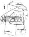
- Fig. 1 shows a schematic representation of a "cut" house with a chimney also shown in section.
- a compressor 10 parked on the floor is connected to a fluid motor 12 which is drained off in the chimney and is designed as a pneumatic motor via a fluid hose 14 which supplies compressed air.
- the fluid motor carries a milling tool 16, which is here formed by chains, e.g. but can also be formed by a suitably designed milling crown.
- the milling tool 16 When the fluid motor 12 is pressurized with the compressed air, the milling tool 16 is set in rotation and thereby mills the chimney to the desired diameter, also with removal of sooting in the inner shell of the chimney and with the removal of protruding wall parts.
- the chimney is continuously milled from bottom to top by slowly pulling up the fluid motor 12 together with the milling tool 16.
- Working from top to bottom is also possible, e.g. with the milling crown mentioned.
- a suction device is introduced, through which the dust that is formed is suctioned off.
- a pressure oil pump 10 can replace the compressor 10 and the pneumatic motor and a hydraulic motor as the fluid motor 12.
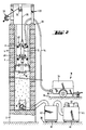
- a chimney 4 here as a house chimney, is erected on a chimney foundation 2 and has an outer chimney construction 6 running all around and an inner shell surrounded by it, which is provided as an inner pipe string 8 carrying flue gas.
- the load-bearing chimney structure 6 is shown here as masonry made of artificial or natural stones and the inner pipe string 8 as a continuous layer, for example made of centrifugal cement. Any other single or multi-layer chimney construction with or without additional intermediate shells, such as thermal insulation layers or vapor diffusion insulation layers, is alternatively possible.
- the inner pipe string can also consist of fireclay or steel pipes and can also consist in the usual way of axially adjoining and mostly sealed by grout or other sealing strands.
- a chimney slide 18 In the area of the lower end of the chimney 4 above the chimney foundation 2 there is an opening with a chimney slide 18 through which soot is usually removed.
- the chimney 4 ends at the top in a frontal plateau 20, on which a chimney head (not shown), in the case of more modern chimneys, possibly via an end plate (not shown), can be placed on the building.
- the chimney 4 is expediently milled out with the chimney head removed and, if appropriate, also with the end plate removed.
- a support frame or support frame 22 is mounted so that it is immovable laterally, for example by Clinging on the upper outer chimney edge.
- the supporting frame 22 carries a roller 24, via which the fluid hose 14 in the arrangement according to FIG. 1 and a pull rope in the arrangement according to FIGS. 2 to 4 26 is performed.
- the fluid motor 12 is suspended here on this traction cable 26, for which purpose the fluid hose 14 itself is used according to FIG. 1. If this fluid hose 14 itself is to take over the traction function, it must be designed to be suitably tensile, for example by a tensile hose reinforcement or hose casing.
- the cable winch 28 or a hose unwinding roller are rigidly attached to the support structure with their shaft during operation, so that the winding forces are absorbed via the support structure at the upper end of the chimney 4.
- the cable winch 28 is expediently adjustable in height.
- the fluid hose 14 is here guided separately from the pull cable 26 from the upper end of the chimney 4 and connected to a compressor (cf. compressor 10 in FIG. 1) outside the chimney, which is driven by an internal combustion engine, expediently a diesel engine. Both the compressor and the internal combustion engine are mounted on a chassis 30 with a parking brake 32 and surrounded by a sound-absorbing hood 34.
- the chassis 30 can on any flat base 36, next to the building in which the chimney 4 is built, set up and braked against this base.
- about two electric motors 46 or, alternatively, compressed air motors can be provided, which can then be appropriately fed by the compressor arranged under the hood 34.
- the two electric motors 46 enable the available drive power to be multiplied correspondingly when supplied by local mains voltage and can thus save a high-voltage connection. If necessary, more than two such motors 46 can also be provided.
- the main separator is designed, for example, as an industrial vacuum cleaner and is connected via the suction lines shown through the opening of the chimney slide 18 to the floor space of the chimney 4 above the chimney foundation 2.
- the milling tool 16 shown in FIG. 2 is described in more detail below with reference to FIG. 14.
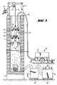
- the milling tool 16 used in FIGS. 3 and 4 is described in more detail below with reference to FIG. 15.
- the fluid motor 12 also carries a guide 48, as is described in more detail with reference to FIGS. 9 and 10a to 10d.
- the fluid motor 12 itself has the type described below with reference to FIG. 5, possibly with FIG. 6, which requires guidance.
- the guide 48 is omitted with the basic construction according to FIGS. 2 to 4 remaining the same.
- the flue gas-carrying inner pipe string 8 is milled in one go from bottom to top, in the arrangement according to FIG. 4 also in one go from top to bottom.
- the inner layer 8 interpreted here as inner pipe string 8 could also only be used include an inner zone detected during the milling process, with radially successive zones being able to be removed downwards, upwards, downwards, etc., one after the other, in alternating milling operations.
- Post-processing steps, such as finishing operations can also be carried out by changing the milling tool 16 by means of the same fluid motor 12.
- the milling tool 16 can optionally also be arranged at the top and the fluid motor 12 at the bottom in a manner not shown; however, this presents the difficulty of having to direct the fluid motor through the body of the milling tool when it is supplied from above or, alternatively, of supplying the fluid hose 14 from the start through the opening of the chimney slide 18, or another opening.
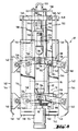
- the pneumatic motor 12 shown in FIG. 5 has a cylinder 50, along the axis of which the rotor 52 of the pneumatic motor 12 extends.
- the cylinder 50 is delimited on the outside and inside by a cylinder surface, but the inner cylinder surface is arranged eccentrically to the outer cylinder surface.
- the cylinder 50 has a correspondingly changing wall thickness.
- the rotor 52 has a cylindrical outer surface which, with the eccentric inner surface of the cylinder 50, delimits a compression space 54 (shown in cross-hatching).
- the rotor 52 is in turn attached to a rotor shaft 56.
- Slits 58 extending tangentially to the rotor shaft 56 are distributed over the circumference of the rotor 52, which is formed from a solid cylinder shell, and extend over the entire axial length of the rotor 52 and end at a radial distance from the rotor shaft 56. In practical embodiments, between four and six such slots are provided, for example. Rotor blades are loosely inserted in the slots. While the fluid motor 12 can otherwise be made of steel, the rotor blades 60 can be made of a suitable plastic, for example of phenoplasts or melanin resins, such as are sold under the protected trade name "Pertinax", for example.
- the rotor lamellae 60 are rectilinear on their longitudinal edge interacting with the cylindrical inner surface of the cylinder 50 and complementary to a corresponding one on their longitudinal edge engaging in the slots Basic design of the slots is flattened to be axially guided in the slots in their radially lowest engagement position.
- the rotor lamellas are pressed outwards into contact with the inner wall surface of the cylinder 50. They divide the compression space 54 into traveling chambers distributed over the circumference of the rotor shaft, short-circuit air between the chambers being largely avoided by sufficiently close contact of the slots on the rotor lamellae.
- two continuous axially parallel bores 62 run alongside one another in the circumferential direction, via which the compressed air supplied by the compressor 10 via a compressed air hose 14 is fed to the compression space 54 via four slots 64.
- the slots 64 extend in the circumferential direction of the cylinder 50 and are arranged in pairs in the vicinity of the two ends of the cylinder.
- Radially through outlet holes 66 are distributed in the sickle of the tapering wall thickness of the cylinder, which decreases in the running direction of the rotor 52, and several, for example five, of these holes are expediently arranged in several, for example two, rows across the axial area between the slots 64 Distributed circumference of the cylinder 50.
- the cylinder 50 is sealed off at both ends by a cover 68.
- Each cover 68 carries on its side facing away from the compression space 54 a ball bearing 71 for the rotor shaft 56, which extends through axial openings in both covers 68 and is secured against axial displacement.
- the rotor shaft 56 is extended beyond the ball bearing 71 as an input shaft of a single-stage reduction gear, here a planetary gear.
- the planetary gear corresponds to the lower half of the exposure drawing according to FIG. 6, in the upper half of which further elements for the two-stage design of the reduction gear are shown, here an axially connected two-stage planetary gear.
- a pinion 70 is seated on the driven end of the rotor shaft outside the cylinder 50.
- This pinion engages in an internal toothing of a planet gear cage 72.
- the planet gears 74 supported in this mesh with a sun gear ring 76.
- This is rigid on the inside of a pot-shaped extension 78 of an output shaft 80 , on which the shaft of the milling tool 16 is coupled in a rotationally fixed manner.
- a second planetary gear stage is arranged axially between the output shaft 80 and the described first stage of the planetary gear, the elements of which in FIG. 6 are identified with the addition a while the functional parts are otherwise the same.
- first stage of the planetary gear is not connected directly to the output shaft 80, but that with an otherwise identical design as the end of the output shaft facing the pneumatic motor, an axially aligned intermediate shaft 82 is used, on which a pinion 70a sits, which corresponds to the pinion 70 in the force introduction function at the input of the first gear stage.
- the entire unit which is described by the cylinder 50 together with covers 68, the rotor shaft 56 mounted therein and the planetary gear (85) (designated as a whole) (85), is surrounded by a two-part solid armored housing 84 on its side facing the suspension and all around , wherein a solid lower end plate 86, which carries a first ball bearing 88 for the output shaft 80 on the inside and is connected tightly to the armor housing 84, closes the housing on the side facing the milling tool 16.
- the output shaft 80 is also supported by a second ball bearing 90, which is fastened to the inside of a first part 92 of the tank housing.
- This first part 92 is arranged in the form of a hood and, starting from the end plate 86, comprises all the above-mentioned parts of the output housing (s) and pneumatic motor, the hood base 94 being opposite the free end 96 of the rotor shaft 56 opposite the output shaft 80.
- the cylinder 50 is provided with a slightly protruding ring flange at each of its two ends, and these ring flanges are tightly fitted into the housing of the first part 92 of the armored housing 84. This creates a certain annular gap between the outer surface of the cylinder 50, the two ring flanges and the inner surface of said first part 92, through which the exhaust air from the compression space 54 emerging from the outlet holes 66 can be freely distributed. This exhaust air can escape radially further outwards through a ring of outlet holes distributed over the wall of the first part 92 in the circumferential direction.
- the compressed air is fed to the pneumatic motor through an inlet nozzle 100 projecting axially upwards, which is integrally formed in the hood bottom 94. From there, the compressed air reaches the bores 62 via the free space 102 formed below the hood base 94 within the first part 92 and from there finally into the compression space 54 in the manner described.
- the second part 104 is screwed around the outside on the side of the suspension of the fluid motor. As will be described later with reference to FIG. 9, the entire unit of fluid motor 12 and milling tool 16 is suspended from this second part 104.
- the second part 104 surrounds the first part 92 of the armor housing 84 to below the exit holes 98 and is screwed into a recess on the first part such that both parts 92 and 104 of the armor housing 84 have a common, small-diameter cylindrical outer surface.
- annular gap 106 is formed in the overlapping area between the two parts 92 and 104 of the armor housing 84, which lies opposite the exit holes 98 and is sealed in the area of the joint located underneath between the two parts of the armor housing.
- the annular space 106 is extended radially inward in relation to the outer end face of the hood base 94 by an annular gap 108 between the outer end face of the hood base 94 and a massive continuation part 110 of the second part 104 which leads axially upward.
- a radial bore 112 is first formed, which extends outside the tank housing with an inlet connection piece extending axially next to it leads to the connection with the compressed air hose 14. This connection bore 112 is sealed off from the outer end of the inlet connector 100 on the hood base 94.
- the annular gap 108 communicates with axially and radially extending bores 105 and 107 in the continuation part 110 of the second part 104 of the armored housing 84, in order to finally exhaust the air from the pneumatic motor through an exhaust shaft 114 attached to the side of the armored housing, and during milling to escape into the interior of the chimney.
- the exit direction of this exhaust shaft is chosen axially parallel to the milling tool 16.
- the exhaust air escaping only over a portion of the circumference of the armor housing is distributed as a jacket flow in such a way that not only blowing on the milling tool is possible, but also a barrier against the rising of milling dust over the entire circumference of the armor housing.
- the pneumatic motor according to FIG. 7 can basically be constructed in the same way, without prejudice to the graphic deviations in FIG. 7.
- the torque transmission from the pneumatic motor to the milling tool takes place here in the absence of a reduction gear in the ratio 1: 1, i.e. directly.
- the free end of the rotor shaft 56 protruding from the cylinder 50 on the milling tool 16 side is connected to an output shaft 115, which corresponds to the output shaft 80 according to FIG. 5, via a striking mechanism 117.
- This converts the continuous rotary movement of the rotor shaft 56 into a rotary impact movement with impact action in the angular direction due to one per revolution of the Rotor shaft effective interaction of a so-called hammer and a so-called anvil of the striking tool.
- An axial oscillation of the milling tool 116 can be dispensed with entirely if an axial component could also be included if necessary.
- An essential feature of switching on such a striking mechanism is to compensate for a counter torque occurring when the milling tool 16 is working - an elastic hammer blow between the hammer and anvil of the striking mechanism per revolution - by the impact of the impact in the striking mechanism.
- the output shaft 115 is hollow, with a polygonal inner cross section, in particular as a hexagon. This allows marketable Milling tools, which are generally provided with a hexagon connection, can be simply plugged in while transferring very high torques.
- a corresponding plug-in piece 118 of a milling tool 16 is shown in FIG. 7.
- the bore of the hollow output shaft 115 can also be used as a supply channel for control fluid, in particular compressed air, for the milling tool.
- a control line connection 120 is led out at the milling-side end of the hollow shaft, for example in order to reverse a milling tool which can be reversed for working directions upwards and downwards when the working direction changes.
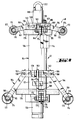
- FIG. 8 and 9 to 11 show two possible preferred construction types of positive guides which can be used in the construction of a pneumatic motor according to FIG. 6 which requires torque support. Both types are characterized by a relatively little covered viewing gap between the tank housing 84 and the inner surface of the chimney 4.
- connection coupling 124 here a so-called socket, for connecting the output shaft 80 according to FIG. 5 to the milling tool 16.
- an eyelet 122 is provided at the upper end on the second part 104 of the tank housing, on which the Pull rope 26 can be latched.
- the connecting piece 126 which is arranged here laterally on the tank housing and communicates with the connecting bore 112, on the fluid motor analogously to the eyelet 122 in a manner not shown and train to transmit force, ie with connecting means to the reinforcement or tensile casing of the fluid hose 14.
- a retaining washer 128 is arranged with sufficient axial spacing for guidance in the area of both ends of the armor housing 84 (see in particular also FIGS. 10a and 10b, in which the retaining washer 128 in plan view and in Side view is shown).
- the retaining washer is clamped along the action line 130 shown in dashed lines in FIG. 10a by means of tensioning screws 132 on the outer circumference of the armored housing 84.
- the dashed double line 134 in FIG. 10 a describes in the large square cross section of the holding disks 128 in the area of the center of the boundary lines of the square a pivot axis 134 for swivel arms 136.
- These are straight levers, one end of which in the area of the axis 134 on a pivot pin 138 on the armored housing 84 is articulated and the other end is articulated to a cheek 140 on the radially inner side of a runner 142.
- four runners 142 are distributed over the circumference of the pneumatic motor. These have an elongated, at least approximately rectilinear central section 144 and, at the top and bottom, ends 146 which are each curved inwards or at an angle.
- the outer surface of the armor housing 84, the runners and the two swivel arms articulating the respective runners above and below form a parallel guide linkage.
- All four parallel guide rods are radial in their axially displaceable actuating plate 147 Width adjusted together.
- the circumference of the actuating plate in the region of a linkage 148 is connected to a linkage 152 in the central region of the respective upper swivel arm 136 via a pull lever 150 which extends along the outside of the tank housing.
- the actuating plate 147 is axially displaceably guided on two diagonally opposite guide rods 154.
- the guide rods in turn are screwed with their lower ends into the upper holding disk 128 and connected at their upper ends by a transverse yoke 156 to which the eyelet 122 is welded.
- the actuating plate 147 lies in its lowest position due to the weight of the rods with runners articulated on it.
- a pneumatically actuated servo cylinder 158 is used to lift the actuating plate 147, which is fastened to the end face of the armor housing 84 and can be loosely supported with its stamp 160 at the axial center of the actuating plate.
- a fastening 162 at the point of attack on the actuating plate 147 is preferred.
- the holding disk 128 is bevelled at the corners of its large square floor plan, and in each of the corners a radially extending incision 163 is provided, which in the area of the line of action 130 for tightening on the circumference of the Armor housing is formed as a continuous slot as in the above-described embodiment.
- the free end of the lever is formed with a one-sided projection as fork 169, a shaft 172 being arranged on the two arms 170 of fork 169, on each of which a cutting wheel 174, or alternatively a roller or roller, is rotatably mounted.
- An elastic, flexible buffer element in the form of a circumferential cellular rubber ring 176 is secured against the axial displacement, under which the central area of the respective lever lies loosely to limit its downward pivoting position. If necessary, the axial position of this buffer element 176 can also be adjusted. With the appropriate setting, it is also possible to choose the same or desired different radial exposure (for example in adaptation to the conical shape of the chimney) with different lengths of the levers 164. In this sense, the upper levers 164 are drawn with a shorter length than the lower levers 164. The somewhat further radial projection of the lower levers 164, which can also be seen in FIG.
- a notch 178 can be seen in FIG. 9 on the outer circumference of the armored cylinder. This notch 178 is opposite a corresponding parallel notch on the covered other side. As a result, the two parts 92 and 104 of the armor housing 84 can be screwed on with a tool by applying a sufficient torque.
- the guide rods 154 of the embodiment according to FIG. 8 are replaced here by a connecting pin 180 which is fixed at the top by the eyelet 122 and is rigidly connected to the end face of the armored housing 84 at the bottom.
- the connecting pin 180 a solid cylinder, with a smaller diameter than the armored housing 84.
- This has the advantage of being able to arrange the upper levers 164 with a particularly small radial projection. Because of the greater load on the lower levers, the problem does not arise to such an extent. All in all, this has the possibility of adapting to particularly small clear chimney widths.
- Fig. 11 shows a simple modification with which the same structure of the guide can be designed double-acting, with a constant geometry without the need for conversion work.
- the levers which are arranged in the form of a ring at the top and bottom, are connected to one another by tension elements 182 which extend along the armor housing 84 and which are expediently tension springs.
- tension elements 182 which extend along the armor housing 84 and which are expediently tension springs.
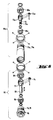
- the milling tool has a central support body 192 around which milling-effective elements held by the support body extend.
- the upper end of the support body is shown here as a square, with hexagons instead being provided in the case of a design which complies with the standards.
- These are rigidly attached to the output shaft of the respective fluid motor 12 in axial alignment with its effective axis via fastening pins 194 which engage in corresponding fastening bores in the support body 192.
- fastening pins 194 which engage in corresponding fastening bores in the support body 192.
- the support body 192 extends with a constant cross section over the entire axial height of the milling element.
- the lower end is formed as a support 196 which is fastened axially immovably to the support body 192 via a fastening pin 194.
- spacer sleeves 198 and spacers 200 are loosely attached to the support body.
- the spacers 200 are preferably arranged equidistantly, in which case the spacer sleeves 198 arranged between them each have the same axial length or can each be of the same design.
- the bottom spacer sleeve 198 can be made shorter, as shown. Alternatively, you can do without them entirely and place the lowest spacer directly on the support 196.
- each spacer disk has a single chain link 202 distributed around the circumference of the milling tool, each chain link 202 carrying a milling disk 204 at its outer end.
- FIG. 12 an illustration is drawn in FIG. 12, in which the rotational state of the milling tool is assumed, so that the outer chain links 202, which are connected in a chain-like manner to both the spacer disks 200 and the milling disks 204, fly horizontally outward, as is also the case in FIG. 1 for longer chain-like Milling tools is shown.
- the idle state such chains hang down under their own weight so that they can then easily be passed through areas of the chimney that have not yet been milled out.
- the milling disks 204 describe an active cone which initially widens conically from top to bottom and then tapers again conically, and which is axially symmetrical with respect to the middle spacer disk 200a in order to be able to mill equally effectively both upwards and downwards with the same geometry. Since the milling disks of the middle spacer 200a are subjected to the greatest stress due to their largest radial projection and should therefore be chosen to be particularly robust in each case, it is also advisable, as shown, to make the middle spacer 200a stronger than the other spacers (with the same Material with greater thickness). The spacers have different radial widths corresponding to the respective radial radius of the active cone at the point in question, while the individual chain links 202 can all be selected in the same way.
- the support body 192 is, as mentioned with regard to the milling tool described above, provided with a lower support, not shown, analogous to the support 196, on which a single elongated spacer sleeve 198a rests (instead of the majority of the spacer sleeves) 198 and spacers 200 of the previously described embodiment).
- support plate 206 is arranged, which is square here.
- a radially extending slot 208 is formed in each of the four corner regions of this square support plate 206, in each of which a set screw 210 engages from the sides facing away from the spacer sleeve 198a.
- a set screw 210 engages from the sides facing away from the spacer sleeve 198a.
- four bow-shaped milling blades 212 can be pivoted out over the circumference of the milling tool, but can also be fixed in a specific angular position when the set screws 210 are tightened.
- the milling blades 212 can be freely axially displaced along the elongated holes 208, this displaceability also being excluded when the adjusting screw is tightened.
- the milling tools each have a cutting edge 214 on at least one outer narrow side. It is also conceivable to provide a cutting edge 214 on both edges of the milling lamella, although only one cutting edge is used in one working direction, be it for working under different operating conditions, be it for reverse assembly for subsequent wear of both cutting edges.
- the cross section of the milling lamella 212 can also be selected such that a cutting edge 214 is only possible on one edge.
- the cutting edges 214 are also radially axially from top to bottom issued on the outside to describe a conical knitting cone again. If the working direction is reversed, this workpiece can also be repositioned by exchanging the legs of the bow-shaped milling blades, on which the set screws 210 engage between the support plates 206.
- this workpiece can also choose to issue the milling lamella itself in the manner of a double cone, as has already been described with regard to the embodiment according to FIG. Here the double cone would then be formed by the same milling element.
- articulations of the bow-shaped milling lamellae can also be provided simply via individual chain links, as is the case in the embodiment according to FIG. 12 with regard to the connection of the spacer disks 200 there with the outer milling disks 204 on the basis of the individual ones Chain links 202 is described.
- a support disk 216 is fastened to the lower end of the support body 192 in a manner similar to the previously described support 196, for example by means of a fastening screw, not shown, with which the support disk 216 is attached to the form-fitting from below is partially screwed into the support body 216 engaging support body 216.
- Each rectangular groove 218 which are equidistant in the circumferential direction and which run axially are distributed over the circumference of the support disk 216.
- an oscillating block 220 which forms a straight, short lever and essentially occupies the width of the rectangular groove with relative mobility, is articulated on a bearing pin 222 so as to be oscillatable.
- the bearing pin 222 is driven in with a form fit by means of through bores 224 opposite each other on the respective rectangular groove 218.
- the oscillating blocks are essentially flush with the upper end face of the support disk 216.
- the upper ends of the oscillating blocks 220 are also beveled at least on their radially inner side of the milling head.
- a roof 226 of the same type inside and outside is shown with a flat ridge design.
- the ridge is essentially flush with the surface of the support plate 216 after the pivoting position of the oscillating block 220, while the radially inner roof slope 228 strikes the base of the rectangular groove 218 at a predetermined pivoting position of the oscillating block 220 and thus limits the pivoting out.
- the double-sided roof design can be used to reverse the direction of installation if the vibrating block wears on one side.
- a threaded bore 230 is recessed.
- a high stress-absorbing stud 232 is screwed in, which, with a little radial play, serves as a bearing shaft for a cylindrical shell-shaped base body 234 of a milling head 236.
- the milling head is complemented by milling pins 238, which fit into the cylindrical circumferential surface of the base body 234 are rigidly embedded and protrude radially from this peripheral surface, so that the base body and burrs together form a kind of radial hedgehog.
- the burrs have the same length, so that the peripheral surface of the hedgehog describes a cylindrical, but possibly also a different envelope surface, for example an envelope surface slightly bulged in the middle axial length.
- the pins themselves are straight and made of hard metal, for example a steel alloy or other hard metals or hard metal alloys.
- the receiving holes of these rows are offset from one another with a gap, the rows being arranged equidistantly.
- the head of the respective stud 232 is embedded in the base body on its outer end face.
- this tool can be used with the same geometry working both downwards and upwards, with a support body 192 then optionally being provided on both end faces the support disc 216 provides.
- a support body 192 then optionally being provided on both end faces the support disc 216 provides.
- the oscillating blocks 220 which act as straight oscillating arms, can still hang vertically downwards somewhat freely, if the milling tool is not set in rotation. Then the outer enveloping surfaces of the three milling heads 236 are supported against one another in such a way that all three milling heads are essentially axially aligned, so that insertion into a chimney cross-section which has not yet been milled is conveniently possible.
- the vibrating blocks can also be brought into contact with their internal longitudinal surface at the bottom of the rectangular groove 218 in this operating mode. You can also design the bottom of the "rectangle" groove bulged, in order to hold the vibrating block axially if necessary.
- the embodiment shown does not permit a double-acting operation in terms of its geometry without repositioning a support body 192 provided on both sides when attaching it to the output shaft of the fluid motor 12.
- the stop of the oscillating block 220 on the bottom of the rectangular groove 218 can be made detachable by means of a servo device such that the oscillating block is pivoted out of the hanging arrangement according to FIG. 5 into an essentially standing arrangement and there also by an outside, also servo-adjustable support is fixed.
- a servo control can in turn be carried out by means of the same equipment which is used for the operation of the fluid motor 12, but via a separate control line.
- Such a striking mechanism can also be arranged at a different location, in particular between the fluid motor and its suspension, it is described below in a direct connection after the rotor of the fluid motor. In this respect it replaces a separate reduction gear, in which the torque amplification of a reduction gear is exchanged for an increase in effectiveness by hammering.
- a separate reduction gear in which the torque amplification of a reduction gear is exchanged for an increase in effectiveness by hammering.
- a hammer carrier 242 of the striking mechanism is driven with a ratio of 1: 1 by the rotor 52 of the pneumatic motor.
- Two hammers 246 and two hammer pins 244 are loosely arranged in the hammer carrier 242 at diametrically opposite circumferential locations, the hammer pins 244 as end stops limiting a movement of the hammers 246 radially outwards under the centrifugal force.
- the hammers 246 are carried in the direction of rotation.
- the arrangement of the hammers 246 in the hammer carrier 242 is designed differently, which manifests itself in different circumferential lengths of the circumferential grooves to be accommodated and their different geometries.
- the hammers 246 make a wobbling movement.
- the hammers 246 interact in the direction of rotation with an anvil 248, which forms a non-rotatable, preferably rigid, unit with the output shaft 80 carrying the milling tool 16.
- the anvil 248 is supported in the impact tool housing 250 via the bearing bush 252.
- the output shaft 80 is thus also given a uniform mounting.
Landscapes
- Engineering & Computer Science (AREA)
- Mechanical Engineering (AREA)
- Mining & Mineral Resources (AREA)
- General Engineering & Computer Science (AREA)
- Working Measures On Existing Buildindgs (AREA)
- Finish Polishing, Edge Sharpening, And Grinding By Specific Grinding Devices (AREA)
- Milling Processes (AREA)
- Structures Of Non-Positive Displacement Pumps (AREA)
- Drilling And Boring (AREA)
Abstract
Description
Die Erfindung bezieht sich auf eine Vorrichtung gemäß den Merkmalen des Oberbegriffs von Anspruch 1. Die Erfindung bezieht sich ferner auf Anwendungen der Vorrichtung gemäß den Ansprüchen 19 bis 22.The invention relates to a device according to the features of the preamble of claim 1. The invention further relates to applications of the device according to claims 19 to 22.
Es ist ständige Aufgabe von Kaminkehrern, Kesselreinigern und sonstigen Rohrreinigungspersonen, Abgasrohre von Ablagerungen des Rauchgases zu reinigen und dabei den ursprünglichen lichten Querschnitt solcher Rohre wieder herzustellen. Dies erfolgt teils manuell, teils mittels motorischer Servounterstützung. Selbst hartnäckigere Ablagerungen lassen sich dabei mit relativ geringem Kraftaufwand beseitigen, so daß im allgemeinen bürstenartige Reinigungswerkzeuge und relativ schwach ausgelegte Servomotoren ausreichen. Ein Beispiel einer Reinigung von Rauchgasrohren einer Kesselanlage zeigt dabei die FR-A 2 074 527. Bei dieser vorbekannten Einrichtung wird eine Reinigungsbürste zusammen mit einem von Druckluft angetriebenen Pneumatikmotor in das zu reinigende Kesselrohr eingeführt. Des Einsatz von Fluidmotoren bei der Reinigung von Kaminzügen ist darüberhinaus aus der DE-A-2 756 561 bekannt. Die Einrichtung wirkt dabei der Art nach nicht als Fräseinrichtung, sondern als Radialschleifmaschine (vgl. auch die mit einer Waschbürste arbeitende DE-A1 29 53 685). Ein Schornsteinreinigungsgerät mit Servomotor zeigt die nicht vorveröffentlichte DD-A1 262 073. Feste Rückstände werden hierbei zunächst mittels eines Fräskopfes abgetragen. Dann wird der Fräskopf durch einen Bürstenkopf ersetzt und die Innenwandfläche des Schornsteins weitergereinigt. Bei allen diesen bekannten Reinigungsmethoden soll die Innenwandfläche des zu reinigenden Rohres möglichst unverletzt freigelegt werden.Chimney sweepers, boiler cleaners and other pipe cleaners are constantly tasked with cleaning exhaust pipes from deposits of flue gas and thereby restoring the original clear cross-section of such pipes. This is done partly manually, partly by means of motorized servo assistance. Even more stubborn deposits can be removed with relatively little effort, so that brush-like cleaning tools and relatively weak servomotors are generally sufficient. FR-
Ungleich schwieriger ist die Sanierung von sanierungsbedürftigen Altbau-Schornsteinen, womit sich die Erfindung ausschließlich befaßt.The renovation of old building chimneys in need of renovation is much more difficult, with which the invention is concerned exclusively.
Die Sanierungsbedürftigkeit kann dabei sehr unterschiedliche Gründe haben. So kann nur beispielsweise das ursprüngliche Rauchgas führende Rohr infolge von Versottung, Sprüngen, Mürbe-Werden, Rauchgas-durchlässig-Werden, Verlust der Wärmedämmung oder nach neuzeitlichen Bewertungen zu kleine Wärmedämmung, oder aus anderen Gründen nicht mehr funktionsfähig sein. Es kann auch die Einbringung einer inneren Auskleidungsschicht in einem ersten Sanierungsversuch untauglich gewesen oder geworden sein. Schließlich kann es sich bei an sich noch intakten Schornsteinstrukturen um eine Änderung des gewünschten lichten Querschnitts handeln. In allen diesen Fällen muß in den sanierungsbedürftigen Schornstein ein neuer Rauchgas führender Innenrohrstrang eingezogen werden (sogenanntes Ausfüttern), in bestimmten Fällen mit zusätzlichem radialen Abstand außerhalb dieses einzuziehenden Innenrohrstranges, sei es wegen der Notwendigkeit, zusammen mit diesem noch eine Wärmedämmschicht einzuziehen, sei es zur Anordnung eines sonstigen Zwischenraums, beispielsweise für Hinterlüftungszwecke. Nun muß der neue Rauchgas führende Innenrohrstrang jeweils einen vorgegebenen Innen- und damit auch einen größenordnungsmäßig vorgegebenen Außendurchmesser haben, so daß in aller Regel ein Einziehen des zur Sanierung verwendeten neuen Innenrohrstrangs in die schon vorhandene lichte Weite des sanierungsbedürftigen Schornsteins nicht in Frage kommt. Deshalb ist in allen diesen Fällen erforderlich, in dem sanierungsbedürftigen Schornstein mindestens dessen bisherige Rauchgas führende Innenschale vor dem Einsetzen von Sanierungsrohrelementen zu entfernen. In vielen Fällen mehrschaliger Schornsteinkonstruktionen wird man dabei das ganze ursprüngliche Rauchgas führende Innenrohr entfernen müssen. In anderen Fällen, wie bei dem genannten Beispiel einer Nachsanierung eines vorhergehenden fehlgeschlagenen Sanierungsversuchs, mag es dabei ausreichen, eine Ausschleuderschicht o. dgl. wieder abzutragen, gegebenenfalls mit Randzonen der ursprünglichen Schornsteinkonstruktion.The need for renovation can have very different reasons. For example, only the original pipe carrying the flue gas can become inoperable due to sooting, cracks, becoming worn, becoming flue gas permeable, loss of thermal insulation or, according to modern assessments, thermal insulation too small, or for other reasons. The application of an inner lining layer in a first attempt at refurbishment may or may not have been suitable. Finally, chimney structures that are intact per se can be a change in the desired clear cross-section. In all these cases, a new flue gas-carrying inner pipe string must be drawn into the chimney in need of refurbishment (so-called lining), in certain cases with an additional radial distance outside this inner pipe string to be pulled in, be it because of the need to pull in a thermal insulation layer together with this, be it for Arrangement of another space, for example for ventilation purposes. Now the new flue gas-carrying inner pipe string must each have a predefined inner and thus also an order of magnitude predefined outer diameter, so that, as a rule, pulling the new inner pipe string used for refurbishment into the existing clear width of the chimney in need of renovation is out of the question. It is therefore necessary in all of these cases to remove at least the inner shell of the chimney in need of renovation prior to the installation of renovation pipe elements. In many cases of multi-layer chimney constructions, you will have to remove the entire original inner pipe carrying flue gas. In other cases, such as in the example of a refurbishment of a previous unsuccessful refurbishment attempt, it may be sufficient to remove an ejection layer or the like again, possibly with marginal zones of the original chimney construction.
Weiterhin sind die Materialien der Innenrohre bestehender Schornsteine und auch der mit einzubeziehenden Nachsanierungsschichten sehr unterschiedlich und fast immer sehr widerstandsfähig. Nur beispielsweise sind ältere Schornsteine aus Natur- oder Kunststeinen, z.B. bestimmten Ziegelsteinen, aufgemauert oder in einschaligen Formstücken aus Beton mit geformt, insbesondere aus wärmedämmend ausgebildetem Beton. Bei neueren Schornsteinkonstruktionen bestehen die Rauchgas führenden Innenrohre oft aus Schamotte unterschiedlicher Güte bis hin zu Glas-, Keramik- und Edelstahlrohren. Bei älteren Schornsteinen hat man ferner auch die Innenrohrauskleidung aus Elementen nach Art keramischer Fliesen gebildet.Furthermore, the materials of the inner pipes of existing chimneys and also of the rehabilitation layers to be included are very different and almost always very resistant. Older chimneys made of natural or artificial stones, e.g. certain bricks, bricked up or in single-shell moldings made of concrete, in particular made of heat-insulating concrete. In newer chimney constructions, the flue gas-carrying inner pipes often consist of chamottes of different qualities up to glass, ceramic and stainless steel pipes. In the case of older chimneys, the inner pipe lining was also made from elements in the manner of ceramic tiles.
Darüber hinaus sind Schornsteine nicht selten abschnittweise auf Geschoßdeckendurchbrüchen aufgesetzt, so daß beispielsweise im Geschoßdeckenbereich eigentliches Bauwerkmaterial, wie beispielsweise Beton von Böden oder Decken von Räumen sowie darin eingebettete Armierungselemente, auch Armierungseisen, bis in den lichten Querschnitt des Rauchgas führenden Rohres reichen und dort oft sogar Querschnittseinschnürungen bilden. Entsprechende Querschnittseinschnürungen findet man häufig auch dann, wenn Mörtelungsarbeiten beim Versetzen des ursprünglichen Schornsteins unsauber ausgeführt wurden.In addition, chimneys are often placed in sections on floor openings, so that, for example, actual building material in the floor area, such as concrete from floors or ceilings of rooms and reinforcing elements embedded therein, including reinforcing irons, reach into the clear cross section of the flue gas pipe and often even there Form cross-sectional constrictions. Corresponding cross-sectional constrictions are often found even when mortaring work was carried out improperly when moving the original chimney.
Schließlich hat es sich gezeigt, daß in einem ganz erheblichen Anteil sanierungsbedürftige Schornsteine nicht längs einer geraden vertikalen Achse verlaufen, sondern im Einzelfall oft sehr überraschende gezogene Krümmungen und krumme Versetzungen aufweisen.Finally, it has been shown that chimneys in need of renovation do not run along a straight vertical axis, but in individual cases often have very surprising drawn curvatures and curved dislocations.
Es ist bereits in Betracht gezogen worden, die erforderliche Querschnittsvergrößerung eines sanierungsbedürftigen Schornsteins mittels eines Bohrgerätes zu erzeugen (Bezugszeichen 6 in DE-U1 87 01 745.8; siehe auch Bezugszeichen 12 des DE-U1 86 26 492.3). Ein Ausbohren von Schornsteinen ist jedoch überhaupt nur bei bestimmten Materialien der Innenschicht möglich und darüber hinaus unerwünscht, weil unkontrollierbare Druckauswirkungen auf die Schornsteinkonstruktion ausgeübt werden. Für das Ausbohren spricht allein eine relativ günstige Arbeitsgeschwindigkeit.It has already been considered to generate the required cross-sectional enlargement of a chimney in need of renovation by means of a drilling device (
Eine geringere Beanspruchung der Schornsteinstruktur erhält man beim Ausschleifen. Dies ist jedoch mit hohem Zeitaufwand verbunden. Wenn man ferner als schleifend arbeitende Drehwerkzeuge solche mit fliegenden Ketten nach Art der SE-C 177 343 oder der SE-C 177 783 verwendet, kommt es zusätzlich zu waschbrettartigen Riefenbildungen an der Innenfläche des Schornsteins. Das gilt auch dann, wenn diese fliegenden Ketten gemäß der Lehre der WO 86 00 391 der WIPO in unmittelbar axial aufeinander folgenden Ebenen des Drehwerkzeugs angeordnet sind; dabei wird der Waschbretteffekt lediglich gedrängter.Less stress is placed on the chimney structure when grinding. However, this is time consuming. If, in addition, grinding tools with flying chains of the type of SE-C 177 343 or SE-C 177 783 are used as grinding tools, washboard-like grooves are also formed on the inner surface of the chimney. This also applies if these flying chains are arranged according to the teaching of
Unter Verwendung eines Fräswerkzeugs hingegen kann man sowohl eine gute Schonung der bestehenden Schornsteinkonstruktion als auch eine große Arbeitsgeschwindigkeit erreichen. Verbunden ist dies mit einer größeren Vielfalt verwendbarer Werkzeuggeometrien und damit einer besseren Anpaßbarkeit einerseits an die vorgefundenen Gegebenheiten und andererseits an das Arbeitsziel.Using a milling tool, on the other hand, both good protection of the existing chimney construction and a high working speed can be achieved. This is combined with a greater variety of usable tool geometries and thus better adaptability to the existing conditions on the one hand and to the work objective on the other.
Neben den genannten Erweiterungsverfahren der lichten Weite eines sanierungsbedürftigen Schornsteins durch Bohren, Schleifen oder Fräsen ist es auch noch bekannt, eine Schlagwirkung des Werkzeugs vorzusehen. So zeigt die US-A 4 603 747 einen rotierenden Schwinghammer. Dieser ist jedoch nur für Spezialeinsatzzwecke geeignet, hier zum Abschlagen von als Innenauskleidung des Rauchgas führenden Rohrstrangs dienenden Fliesen.In addition to the above-mentioned expansion methods of the clear width of a chimney in need of renovation by drilling, grinding or milling, it is also known to provide an impact effect of the tool. For example, US-A 4,603,747 a rotating rocking hammer. However, this is only suitable for special purposes, here for knocking off tiles serving as the inner lining of the flue gas pipe string.
Es ist schließlich bekannt, ein den lichten Querschnitt eines sanierungsbedürftigen Kamins erweiterndes Drehwerkzeug zusätzlich über ein Schlagwerk in axiale Schlagschwingungen zu versetzen. Auch dies führt jedoch zu unerwünschten Erschütterungen der Schornsteinstruktur (AT-A 325 290).Finally, it is known to additionally set a turning tool, which expands the clear cross section of a chimney in need of renovation, into axial impact vibrations via a striking mechanism. However, this also leads to undesirable vibrations of the chimney structure (AT-A 325 290).
Die Erfindung geht gemäß dem Oberbegriff von Anspruch 1 von der AT-A 203 707 aus, bei welcher neben der Verwendung von Schleif- oder Schlägerwerkzeugen auch schon Fräswerkzeuge in Betracht gezogen sind. Das betreffende Schleif- oder Fräswerkzeug ist bei dieser bekannten Vorrichtung schon zusammen mit seinem Antriebsmotor im lichten Querschnitt des Schornsteins auf und ab bewegbar. Auch die CS-B1 232 019 zeigt einen im lichten Querschnitt eines Schornsteins bewegbaren Antriebsmotor mit angeschlossenem Schneidfräswerkzeug.According to the preamble of claim 1, the invention is based on AT-A 203 707, in which, in addition to the use of grinding or beating tools, milling tools have also already been considered. The grinding or milling tool in question can be moved up and down in this known device together with its drive motor in the clear cross section of the chimney. CS-B1 232 019 also shows a drive motor that can be moved in the clear cross-section of a chimney with a connected milling cutter.
Die Erfindung bevorzugt die Verwendung von eigentlichen Fräswerkzeugen. Soweit von Fräswerkzeugen gesprochen wird, können sie jedoch auch, insbesondere für Sonderanwendungen oder zusätzliche Arbeitsgänge, durch Bohr- oder Schleifwerkzeuge ersetzt werden, die in den Begriff spanabhebender Werkzeuge mit einbezogen sind. Jedenfalls soll Innenwandmaterial des Schornsteins abgetragen und nicht nur eine Innenwandfläche gereinigt werden.The invention prefers the use of actual milling tools. To the extent that milling tools are mentioned, they can also be replaced, in particular for special applications or additional work steps, by drilling or grinding tools, which are included in the term cutting tools. In any case, the interior wall material of the chimney should be removed and not just an interior wall surface cleaned.
Diese vorbekannte Vorrichtung unterscheidet sich hiermit von fernerstehenden Vorrichtungen, bei denen der Antriebsmotor außerhalb des Schornsteins angeordnet ist und sein Drehmoment über eine gegebenenfalls flexible Welle in das Innere des Schornsteins übertragen wird (vgl. DE-A 1 229 230, WO 86/00391 der WIPO).This previously known device differs from further-standing devices in which the drive motor is arranged outside the chimney and its torque is transmitted into the interior of the chimney via a possibly flexible shaft (cf. DE-A 1 229 230,
Bei derartigen Vorrichtungen muß wegen der begrenzten Länge, mit der die drehmomentübertragende Welle ausgebildet werden kann, der Antrieb auf dem Dach aufgebracht werden, wobei eine größere Reichweite als etwa 10 m nur durch eine weitere Ankupplung von flexiblen Verlängerungswellen bei Leistungsverlust erreicht werden kann. Hierbei hat sich das Starten des Antriebsmotors nur dann als möglich erwiesen, wenn das Wellenendstück mit Werkzeug aus dem Schornstein herausgenommen wird. Die biegsame Welle und das Werkzeug bewegen sich dabei also im Freien und stellen für die Bedienungsperson(en)eine große Gefahr dar. Außerdem nutzen sich die Wellen im Betrieb mitsamt ihren Anschlußkupplungen schnell ab und neigen darüber hinaus zum plötzlichen Brechen. Allgemein ist ihre Handhabung problematisch. Ein Einsatz in nicht axial geradlinig verlaufenden Schornsteinen kommt nur höchst bedingt in Frage.In such devices, because of the limited length with which the torque-transmitting shaft is formed the drive can be mounted on the roof, whereby a greater range than about 10 m can only be achieved by further coupling flexible extension shafts in the event of loss of power. In this case, starting the drive motor has only proven possible if the shaft end piece is removed from the chimney with tools. The flexible shaft and the tool therefore move outdoors and pose a great danger to the operator (s). In addition, the shafts, together with their connecting couplings, wear out quickly and also tend to break suddenly. Their handling is generally problematic. Use in chimneys that do not run in a straight line is only of limited use.
Allerdings ist bei der AT-A 203 707 und der CS-B1 232 019 (im Ausführungsbeispiel) jeweils ein elektromotorischer Antrieb vorgesehen. In einer bevorzugten Ausführungsform der bekannten Vorrichtung nach der AT-A 203 707 dient dabei der Stator des Elektromotors zugleich als Führung des Motors an der Kamininnenwand. Bei allen gezeigten Ausführungsformen ist dabei der gerätetechnische Aufwand und der damit verbundene Mindestdurchmesser der Vorrichtung so groß, daß sie nicht zum Ausbohren von Schornsteinen mit Nenndurchmessern von weniger als 150 mm geeignet erscheint. Schon gar nicht erscheint es möglich, eine derartige Vorrichtung durch den lichten Querschnitt eines zusätzlich mit inneren Ablagerungen versehenen Schornsteins dieses Nenndurchmessers hindurchzuführen, um anschließend von unten nach oben zu fräsen.However, the AT-A 203 707 and the CS-B1 232 019 (in the exemplary embodiment) each have an electric motor drive. In a preferred embodiment of the known device according to AT-A 203 707, the stator of the electric motor also serves as a guide for the motor on the inside wall of the chimney. In all of the embodiments shown, the expenditure on equipment and the associated minimum diameter of the device are so great that they do not appear to be suitable for drilling out chimneys with nominal diameters of less than 150 mm. It certainly does not seem possible to pass such a device through the clear cross-section of a chimney of this nominal diameter, which is additionally provided with internal deposits, in order to then mill from bottom to top.
Darüber hinaus erscheinen elektromotorische Antriebe überhaupt nicht für das Einbringen in einen Schornstein geeignet. Nur beispielsweise sei an die Explosionsgefahr in abgeschiedenem Ruß bei Funkenbildung, die Gefahr von elektrischen Kurzschlüssen an leitfähigen Bereichen der Kamininnenwand (z.B. hervorstehenden Metallarmierungen oder infolge Versottung durch Flüssigkeit leitfähig gewordener Bereiche), Brandgefahr wegen Heißlaufens aufgrund der unzureichenden Belüftung bei Vermeidung des zusätzlichen Raumbedarfs von Flüssigkeitskühlung, Unfallgefahr der Bedienungspersonen, großes Arbeitsgewicht, seltene Verfügbarkeit von Starkstrom am Arbeitsort u.dgl. Außerdem neigen von Elektromotoren angetriebene Fräswerkzeuge zum Festfressen im Mauerwerk, selbst wenn man wie im Falle der genannten AT-A 203 707 dagegen wirkende Auskuppeleinrichtungen vorsieht. Auch ist eine feinfühlige stufenlose Regelung nur schwierig möglich. Schließlich deckt die ganze Vorrichtung den Einblickquerschnitt des Schornsteins völlig ab, so daß eine Beobachtung des Fräsvorganges von der oberen Schornsteinmündung her nicht direkt möglich ist. Von unten her kommt ein Einblick schon wegen des herunterfallenden Fräsabhubs nicht in Betracht.In addition, electromotive drives do not appear to be suitable at all for insertion into a chimney. For example, consider the risk of explosion in soot that is separated if there is a spark, the risk of electrical short circuits on conductive areas of the inside wall of the chimney (e.g. protruding metal reinforcements or as a result Sooting due to areas that have become conductive), fire risk due to overheating due to insufficient ventilation while avoiding the additional space required by liquid cooling, risk of accidents for the operators, large working weight, infrequent availability of high-voltage electricity at the place of work and the like. In addition, milling tools driven by electric motors tend to seize in the masonry, even if, as in the case of the aforementioned AT-A 203 707, decoupling devices acting against it are provided. Sensitive, stepless control is also difficult. Finally, the entire device completely covers the cross-section of the chimney, so that it is not possible to directly observe the milling process from the upper chimney mouth. An insight from below is not an option because of the falling milling lift.
Soweit ersichtlich haben - sicherlich aus den genannten Gründen - in den Schornstein mit dem Fräswerkzeug zusammen abgesenkte Elektromotoren in der Praxis keinen Eingang gefunden. Nicht ohne Grund wird im Falle der WO 86/00391 der WIPO der dort auch verwendete Elektromotor außerhalb des Schornsteins angeordnet und dafür der Aufwand in Kauf genommen, diesen Elektromotor über flexible Gestänge mit dem innerhalb des Schornsteins befindlichen Drehwerkzeug, dort Kettenschleifwerkzeug, zu verbinden.As far as can be seen - certainly for the reasons mentioned - electric motors lowered into the chimney together with the milling tool have not found their way into practice. It is not without reason that, in the case of WO 86/00391 of WIPO, the electric motor also used there is arranged outside the chimney and the effort is taken to connect this electric motor to the rotary tool, there chain grinding tool, located inside the chimney via flexible rods.
Sowohl die AT-A 203 707 als auch die CS-B1 232 019 weisen bereits eine mit der Innenfläche des Schornsteins zusammenwirkende Führungseinrichtung für die Auf- und/oder Abbewegung der Arbeitseinheit auf, die Führungs- und Stützelemente hat, deren radiale Abstände zur Motorachse des Antriebsmotors variabel sind. Die Führungs- und Stützelemente führen dabei die Arbeitseinheit und mit dieser das Fräswerkzeug längs der Arbeitsachse im Schornstein und stützen ferner das Arbeitsdrehmoment des Fräswerkzeugs im Schornstein ab. Bei den bekannten Führungseinrichtungen sind die Führungs- und Stützelemente gegenüber dem Antriebsmotor axial versetzt angeordnet, so daß die Gesamtanordnung wenig kompakt ist und die Antriebsachse zwischen Antriebsmotor und Fräswerkzeug der Arbeitseinheit hohen seitlichen Momenten ausgesetzt ist, was zu ungenauer axialer Arbeitsrichtung und Schäden an der Antriebsachse führen kann.Both AT-A 203 707 and CS-
Ausgehend von der AT-A 203 707 liegt der Erfindung die Aufgabe zugrunde, eine Vorrichtung zum Ausfräsen eines auszufütternden Schornsteins zu schaffen, die unter möglichster Beibehaltung der Vorteile der bekannten Vorrichtung gefahrlos, bequem und universell anwendbar ist und eine kompakte, eine optische Inspektion des Arbeitsortes des Fräswerkzeugs von oben ermöglichende Bauweise erlaubt.Starting from AT-A 203 707, the invention has for its object to provide a device for milling a chimney to be lined, which is safe, convenient and universally applicable while retaining the advantages of the known device, and a compact, optical inspection of the work site construction of the milling tool permitted from above.
Diese Aufgabe wird bei einer Vorrichtung mit den Merkmalen des Oberbegriffs von Anspruch 1 durch dessen kennzeichnende Merkmale gelöst.This object is achieved in a device with the features of the preamble of claim 1 by its characterizing features.
Der bei der erfindungsgemäßen Vorrichtung verwendete Fluidmotor kann beispielsweise mit Öl oder mit Druckluft betrieben werden. Im Falle der Verwendung von Druckluft oder eines anderen Pneumatikgases, beispielsweise eines inerten Gases wie Stickstoff, besteht von vorneherein keine Gefahr für den Schornstein. Drucköle wählt man zweckmäßig in einer nicht inflammbaren Art. Sollte derartiges Drucköl in einem verrußten Schornstein austreten, könnte es sogar zur Flüssigkeitsbindung des Rußes und damit zu einer Verringerung der originär vorhandenen Rußbrandgefahr führen. Außerdem neigen Fluidleitungen weniger zu einem Verhaken an Vorsprüngen und Fugen an der Innenfläche eines auszufräsenden Schornsteins als Elektroleitungen.The fluid motor used in the device according to the invention can be operated, for example, with oil or with compressed air. If compressed air or another pneumatic gas is used, for example an inert gas such as nitrogen, there is no danger to the chimney from the outset. Pressure oils are expediently chosen in a non-inflammable manner. If such pressure oil escapes in a sooty chimney, it could even lead to the liquid binding of the soot and thus to a reduction in the original soot fire risk. In addition, fluid lines are less likely to get caught on projections and joints on the inner surface of a chimney to be milled out than electric lines.
Zur Sicherstellung optischer Einblickmöglichkeit von oben längs des Fluidmotors zum Fräswerkzeug sind die als Kufen ausgebildeten Führungs- und Stützelemente für den Fluidmotor im Schornstein zweckmäßig nur lokal um den Fluidmotor herum angeordnet. Im Gegensatz dazu sind bei der AT-A 203 707 die in Betracht gezogenen Führungselemente jeweils ringförmig geschlossen ausgebildet.To ensure an optical view from above along the fluid motor to the milling tool, the guide and support elements for the fluid motor, which are designed as runners, are expediently arranged only locally around the fluid motor in the chimney. In contrast to this, the guide elements under consideration in AT-A 203 707 are each designed to be closed in a ring.
Wesentlich ist dabei, daß die Kufen an wechselnden Innendurchmesser des Schornsteins durch Verstellung anpaßbar sind. Die Kufen, die schlittenkufenartig in ihrem zentralen Bereich leicht gekrümmt und - auch zur Fuhrbarkeit sowohl aufwärts als auch abwärts - an ihren Enden aufgebogen sein können, gewährleisten auch bei Ungleichmäßigkeiten der Innenwand des Schornsteins ein reibungsarmes Gleiten ohne Gefahr, sich zu oft zu verhaken. Zur Verstellung kann man gegebenenfalls das Druckfluid verwenden, das auch als Betriebsmittel des Fluidmotors verwendet wird, jedoch zweckmäßig über eine gesonderte Steuerleitung zugeführt und außerhalb des Schornsteins, z.B. am oberen Schornsteinende, gesteuert wird. Zweckmäßig, jedoch nicht zwingend, verbindet man dabei die Steuerleitung und die Druckfluidleitung zu einem Leitungsteil, beispielsweise durch Zusammenbinden mittels von über die Länge verteilten Befestigungsbändern, insbesondere Klebstreifen.It is essential that the runners can be adjusted by changing the inside diameter of the chimney. The runners, which are slightly curved like sled runners in their central area and can be bent at their ends - also for maneuverability both upwards and downwards - ensure smooth sliding even if the inside wall of the chimney is not uniform, without the risk of getting caught too often. For adjustment, one can optionally use the pressure fluid, which is also used as the operating means of the fluid motor, but is expediently supplied via a separate control line and is controlled outside the chimney, for example at the upper end of the chimney. Appropriately, but not necessarily, the control line and the pressure fluid line are connected to form a line part, for example by tying them together by means of fastening tapes distributed over the length, in particular adhesive strips.
Von besonderer Bedeutung ist die Möglichkeit, den Fluidmotor mitsamt Führungseinrichtung so durchmesserklein bauen zu können, daß er selbst und die an seinem Umfang radial variabel angeordneten Führungs- und Stützelemente bei Schornsteinen sehr geringer lichter Weite in den Schornstein einführbar sind. Dabei läßt sich bei relativ geringer axialer Baulänge sowohl der Antriebseinheit selbst als auch der Antriebswelle zwischen Antriebsmotor und Fräswerkzeug ein sehr hohes Drehmoment übertragen, das bei geeigneter Wahl auswechselbarer Fräswerkzeuge praktisch für alle vorhandenen Wandmaterialien des auszufräsenden Schornsteins in Frage kommt.Of particular importance is the possibility of being able to build the fluid motor together with the guide device so that it can be inserted into the chimney itself and the guide and support elements arranged radially variably on its circumference in the case of chimneys with a very small clear width. With a relatively small axial length, both the drive unit itself and the drive shaft between the drive motor and the milling tool can transmit a very high torque, which, with a suitable choice of interchangeable milling tools, is practically possible for all existing wall materials of the chimney to be milled.
Geringer Durchmesser und geringe axiale Bauweise lassen sich gerade bei Fluidmotoren bequem zu einer im ganzen kompakten Bauweise vereinen. Diese hat eine ganze Reihe von Vorteilen, wie leichtes Gewicht und damit bequeme Erreichbarkeit auch sehr großer Arbeitstiefen, selbst bei Schornsteinen mit rundem Innenquerschnitt ausreichendem optischen Einblickraum zum Arbeitsort des Fräswerkzeugs von oben sowie leichte Führbarkeit längs ungerader Arbeitswege.Small diameter and small axial design can be combined conveniently into an overall compact design, especially with fluid motors. This has a whole series of advantages, such as light weight and thus easy accessibility even at very large working depths, even with chimneys with a round inner cross section, sufficient visual insight into the working location of the milling tool from above, and easy maneuverability along uneven working paths.
Fluidmotoren bedürfen ferner keiner Kühlung, um eine Überhitzung des Motors zu vermeiden. Der innere Aufbau ist technisch einfach und Zugleich robust. Es besteht daher kein Risiko, wenn der Fluidmotor auch in größeren Arbeitstiefen gegen die Innenwandfläche des Schornsteins schlägt. Es läßt sich selbst eine gegen Beschädigung bei Sturz aus großer Höhe sichere Bauart einfach konstruieren. Dabei sind die Betriebselemente gegen den beim Fräsen entstehenden Staub mit einfachen Mitteln, z.B. einem einfachen Gehäuse, abschirmbar, zumal die Elemente eines Fluidmotors von vornherein eine dem Schornstein affine schmale langgestreckte Bauart zeigen. Eine das Betriebsfluid von außerhalb des Schornsteins zur Verfügung stellende Öldruckpumpe, oder im Falle einer Pneumatikpumpe eines Kompressors, kann an beliebigem Arbeitsort einfach mittels eines Verbrennungsmotors, beispielsweise eines modernen geräuscharmen Dieselmotors, angetrieben werden, ohne daß es eines Starkstromanschlusses bedarf.Fluid motors also do not require cooling to prevent the motor from overheating. The internal structure is technically simple and at the same time robust. There is therefore no risk if the fluid motor strikes the inner wall surface of the chimney even at greater working depths. Even a construction that is safe against damage when falling from a great height can be easily constructed. The operating elements can be protected against the dust generated during milling with simple means, e.g. a simple housing that can be shielded, especially since the elements of a fluid motor show from the outset a narrow, elongated design affecting the chimney. An oil pressure pump which provides the operating fluid from outside the chimney, or in the case of a pneumatic pump of a compressor, can be driven at any work location simply by means of an internal combustion engine, for example a modern low-noise diesel engine, without the need for a high-voltage connection.
Aus derartigen Gründen zeichnet sich inzwischen eine allgemeine breite Akzeptanz in allen denkbaren Anwendungsbereichen für die erfindungsgemäße Vorrichtung ab, während alle bisher bekannten vergleichbaren Vorrichtungen allenfalls unter Sonderbedingungen in Frage kamen. Von ganz besonderer Bedeutung sind dabei die Anwendungsfälle der Ansprüche 19 bis 22 für die bisher praktisch überhaupt keine sachgerechte Lösung verfügbar war. Die erfindungsgemäße Vorrichtung ist jedoch wegen ihrer universellen Einsetzbarkeit auf die Anwendbarkeit in diesen Problemfällen nicht beschränkt, sondern es kann bei jeweils angepaßtem Fräswerkzeug derselbe Fluidmotor für alle Anwendungsfälle eingesetzt werden, d.h. selbst ein Fluidmotor sehr geringen Durchmessers bei Schornsteinen maximaler Weite.For such reasons, there is now a general broad acceptance in all conceivable areas of application for the device according to the invention, while all comparable devices known hitherto came into question at most under special conditions. Of particular importance are the use cases of claims 19 to 22 for which, until now, no practical solution was available. However, the device according to the invention is not limited to the applicability in these problem cases because of its universal applicability, but the same fluid motor can be used for all applications with a respectively adapted milling tool, ie even a fluid motor of very small diameter with chimneys of maximum width.
Die erfindungsgemäße Vorrichtung läßt sich sowohl zum Ausfräsen von Rauchgas führenden Innenrohren mit rundem lichten Querschnitt als auch von solchen mit unrundem, beispielsweise etwa rechteckigem oder quadratischem, Querschnitt einsetzen. In allen Fällen ist der Endquerschnitt aufgrund der rotierend wirkenden Arbeitsweise des Fräswerkzeuges rund, wobei bei unrunden Querschnitten zunächst nur eine partielle Aushöhlung des Querschnittes in den durchmesserkleinsten Bereichen erfolgt.The device according to the invention can be used both for milling flue gas-carrying inner tubes with a round, clear cross section and for those with a non-round, for example approximately rectangular or square, cross section. In all cases, the end cross-section is round due to the rotating mode of operation of the milling tool, with non-circular cross-sections initially only partially hollowing out the cross-section in the smallest diameter areas.
Die Verwendung von Drucköl als Betriebsfluid bietet bekanntlich an sich den Vorteil, mit relativ großen Arbeitsdrücken wegunabhängig gestängeartig und damit verzögerungsfrei arbeiten zu können. Gemäß Anspruch 2 wird jedoch die Verwendung von Druckluft oder anderen Pneumatikgasen für den vorliegenden Anwendungszweck des Ausfräsens eines auszufütternden Schornsteins bevorzugt. Selbst wenn es einmal in einer Druckluftleitung zu einem Leck kommen sollte, verschwindet die Leckströmung rückstandsfrei, solange das pneumatische Fluid nicht mit feuchten Anteilen versehen ist, was gemäß nachfolgender Beschreibung sogar bevorzugt sein kann. Aber auch enthaltene Feuchtigkeit verdunstet aus einem Schornstein alsbald.The use of pressurized oil as the operating fluid is known to offer the advantage of being able to work with rod-like and relatively delay-free working with relatively high working pressures. According to
Darüber hinaus läßt sich ein Betrieb mit Druckluft o.dgl. als Betriebsgas sehr einfach stufenlos von der Außenseite des Schornsteins her regeln, indem der Druck der Druckluft über ein Stellventil verändert wird, beispielsweise direkt am Kompressor, aber auch am Ort der Arbeitsperson am Schornstein, z.B. auf dem Dach. Wegen der Kompressibilität eines pneumatischen Druckfluids läuft ferner das Fräswerkzeug auf etwaige Widerstände sanft auf, so daß sich schon von der Betriebsweise her kaum einmal ein Festfressen des Fräswerkzeugs im Schornstein ereignen wird.In addition, an operation with compressed air or the like. The operating gas can be regulated very simply and continuously from the outside of the chimney by changing the pressure of the compressed air via a control valve, for example directly on the compressor, but also at the location of the worker on the chimney, e.g. on the roof. Because of the compressibility of a pneumatic pressure fluid, the milling tool also runs gently against any resistances, so that the milling tool will hardly ever seize in the chimney, depending on the mode of operation.
Besonders wesentlich ist auch die noch durchmesserkleinere Baumöglichkeit von Pneumatikmotoren im Vergleich mit Hydraulikmotoren als Fluidmotoren.Also of particular importance is the still smaller-diameter construction possibility of pneumatic motors compared to hydraulic motors as fluid motors.
Grundsätzlich kann man die Abluft (atmosphärische Luft odersonstiges pneumatisches Druckfluid) über eine gesonderte Auslaßleitung aus dem Schornstein herausführen. Vorzugsweise läßt man jedoch bei der baulichen Anordnung des Abluftauslasses nach Anspruch 3 die Abluft direkt in den Rauchgaskanal des Schornsteins entweichen. Dabei entsteht in diesem Bereich ein Luftpolster mit geringfügigem Überdruck. Es hat sich gezeigt, daß dabei der beim Fräsvorgang gebildete Staub, der im Gegensatz zu größer dimensioniertem Fräsabhub - der von vornherein die Neigung hat, unter der Schwerkraft nach unten abzufallen - die Neigung hat, nach oben aufzuwallen, eine Strömungsrichtung zum Abströmen nach unten aufgeprägt erhält. Dies hat einen doppelten Vorteil. Zum einen kann das Abströmen des gebildeten Staubes nach unten in einfacher Weise ohne oder nur mit geringer Saugleistung erfolgen; dabei kann auch die Saugleistung einer am unteren Ende des Schornsteins etwa angeordneten Absaugeinrichtung kleingehalten werden. Zum anderen kann die Möglichkeit eines geometrischen optischen Einblicksquerschnittes von oben am Fluidmotor vorbei in Richtung auf den Arbeitsort des Werkzeuges für die Bedienungsperson voll nutzbar gemacht werden, da dann der Raum oberhalb des Fräswerkzeuges bzw. des genannten Luftpolsters frei von Staubtrübung bleibt. Ein angenehmer Nebeneffekt ist dabei auch, daß die Bedienungspersonen nicht durch Staubaufwirbelung eingeschmutzt wird.Basically, the exhaust air (atmospheric air or other pneumatic pressure fluid) can be led out of the chimney via a separate outlet line. Preferably, however, in the structural arrangement of the exhaust outlet according to
Wenn gemäß Anspruch 4 der Abluftauslaß sogar noch gezielt nach unten auf das unterhalb des Fluidmotors angeordnete Fräswerkzeug gerichtet ist, kann man dieses kontinuierlich kühlen und von unerwünschten Ablagerungen freihalten. Man kann sogar auf einen Lufttrockner in den offenen Pneumatikkreislauf verzichten; denn es hat sich herausgestellt, daß Feuchtigkeitsanteile in der Druckluft sogar günstig zum Binden entstehenden Feinstaubes sind.If, according to
Es ist an sich bekannt, einen Elektromotor, der mit einem Bohrkopf in den zu sanierenden Schornstein eingeführt wird, von dem oberen Ende des Schornsteins her über eine Führungsstange zu halten und zu führen. Vorzugsweise ist im Rahmen der Erfindung jedoch gemäß Anspruch 5 die Einheit von Fluidmotor und Fräswerkzeug an einem reinen Zugelement aufgehängt, wie dies an sich aus der AT-A 203 707 bekannt ist. In einfachster Ausführungsform kann nach Anspruch 6 als das Zugelement der Fluidschlauch selbst dienen, der dann zweckmäßig tragfähig ausgerüstet sein muß. Alternativ kommt die Verwendung eines gesonderten Zugelementes, wie beispielsweise eines von einer Winde betätigten Zugseils, z.B. aus Stahl, in Frage. Die bei der AT-A 203 707 verwendete Aufhängkette kann man wegen des geringeren Gewichts des erfindungsgemäßen Fluidmotors durch ein derartiges Zugseil problemlos ersetzen. Trotz des relativ geringen Gewichtes einer Einheit aus Fluidmotor und Fräswerkzeug hat es sich gezeigt, daß
beim Fräsen von oben nach unten die Gewichtsbelastung des Fräswerkzeuges durch den Fluidmotor und die sonstigen Elemente der Einheit Fluidmotor-Fräswerkzeug ausreicht, selbst wenn sehr schwer zu fräsende Materialien vorliegen, wie beispielsweise ein wegzufräsendes Schamotterohr oder ein wegzufräsendes Stahlrohr. Entscheidend ist hierbei die richtige Wahl des Fräswerkzeuges. Falls erwünscht, kann man allerdings auch mittels eines Druckelementes im Rahmen der Erfindung von oben nach unten nachdrücken. Beispielsweise könnte man am oberen Ende des Schornsteins einen von demselben Kompressor gespeisten Druckzylinder vorsehen, welcher das Druckelement nach unten hin mit Kraft beaufschlagt. Alternativ kann man in an sich bekannter Weise auch von unten her Zug ausüben (Bezugszeichen 15 in der AT-A 203 707).It is known per se to hold and guide an electric motor, which is inserted into the chimney to be renovated with a drill head, from the upper end of the chimney via a guide rod. In the context of the invention, however, the unit of fluid motor and milling tool is preferably suspended from a pure tension element, as is known per se from AT-A 203 707. In the simplest embodiment, according to
When milling from top to bottom, the weight load of the milling tool by the fluid motor and the other elements of the fluid motor / milling tool unit is sufficient, even if there are materials that are very difficult to mill, such as a chamotte tube or a steel tube that has to be milled away. The decisive factor here is the right choice of milling tool. If desired, however, it is also possible to press down from the top to the bottom by means of a pressure element within the scope of the invention. For example, one could provide a pressure cylinder fed by the same compressor at the upper end of the chimney, which pressurizes the pressure element downwards. Alternatively, you can also train in a manner known per se from below (
Vorzugsweise ist nach Anspruch 7 der Abstand der Kufen von der Achse des Fluidmotors verstellbar. Eine radiale Bewegungsteuerung hierfür sieht Anspruch 8 vor.Preferably, the distance of the runners from the axis of the fluid motor is adjustable. A radial movement control for this provides
Mittels Fluidmotoren, insbesondere Pneumatikmotoren, lassen sich grundsätzlich sehr hohe Drehzahlen erreichen, und zwar bis in Übergangsbereiche vom Fräsen zum Schleifen (20 000 U/min und mehr). Ohne Getriebeuntersetzung lassen sich dabei jedoch nur relativ mürbe Materialien abfräsen.Fluid motors, in particular pneumatic motors, can in principle achieve very high speeds, even in transition areas from milling to grinding (20,000 rpm and more). Without gear reduction, however, only relatively crumbly materials can be milled off.
Für schwierigere Materialien ist es jedoch zweckmäßig, die Einwirkung des Fräswerkzeuges auf das auszufräsende Mauerwerk zu verstärken, sei es durch ein Untersetzungsgetriebe (Ansprüche 9 bis 11), sei es durch zuschaltbare Schlagwirkung in Winkelrichtung (Ansprüche 13 bis 16). Mittels des Untersetzungsgetriebes wird dabei eine hohe Drehzahl des Rotors des Fluidmotors in ein hohes Drehmoment am Fräswerkzeug gewandelt. In beiden Fällen läßt sich das Untersetzungsgetriebe bzw. das Schlagwerk als kurzes axiales Verlängerungsstück ohne zusätzliche Außendurchmessererweiterung vorsehen, im Bedarfsfalle als herausnehmbares Einsatzstück. Untersetzungsgetriebe können dabei insbesondere in Axialrichtung hintereinander mehrstufig ausgebildet sein, wobei sich Planetengetriebe einzeln und in Hintereinanderschaltung als besonders geeignet erwiesen haben.For more difficult materials, however, it is advisable to intensify the action of the milling tool on the masonry to be milled out, be it through a reduction gear (
Der bei der erfindungsgemäßen Vorrichtung vorgesehene Fluidmotor, insbesondere als Pneumatikmotor, ist von seiner Bauart her geeignet, nicht nur in einem bereits ausgefrästen Bereich des Schornsteins mit dem Fräswerkzeug mitgeführt zu werden, wie dies im Regelfall bei Fräsen von oben nach unten der Fall ist, sondern auch um zusammen mit dem Fräswerkzeug durch einen noch auszufräsenden Bereich des Schornsteins zunächst abwärts geführt zu werden, um dann das Fräsen nach oben durchzuführen. Es ist an sich bekannt, Fräswerkzeuge von Vorrichtungen zum Ausfräsen eines auszufütternden Schornsteins mit einem oberhalb des Fräswerkzeuges angeordneten Antriebsmotor über eine flexible Welle zu verbinden und den Kaminquerschnitt unter Auf- und Abbewegung des Fräswerkzeuges zu erweitern (Oberbegriff von Anspruch 1 der DE-A 12 29 230). Ein derartiger Fräsvorgang kann einstufig von unten nach oben erfolgen (vgl. z.B. WO 86/00391 der WIPO) oder mehrstufig unter schichtweiser Ausfräsung, gegebenenfalls mit schlichtender Nachbearbeitung. Die erfindungsgemäße Vorrichtung ist für alle in Frage kommenden Arbeitsweisen aufwärts und abwärts sowie einstufig und mehrstufig geeignet.The design of the fluid motor provided in the device according to the invention, in particular as a pneumatic motor, is suitable not only to be carried along with the milling tool in an already milled-out area of the chimney, as is usually the case with milling from top to bottom, but instead also to be guided downwards together with the milling tool through an area of the chimney that is still to be milled, in order to then carry out the milling upwards. It is known per se to connect milling tools of devices for milling a chimney to be lined with a drive motor arranged above the milling tool via a flexible shaft and to close the chimney cross-section with the milling tool moving up and down expand (preamble of claim 1 of DE-A 12 29 230). Such a milling process can be carried out in one step from bottom to top (see, for example, WO 86/00391 of WIPO) or in several steps with milling in layers, optionally with finishing finishing. The device according to the invention is suitable for all possible working methods upwards and downwards as well as in one stage and in multiple stages.
Alle in Frage kommenden Fräswerkzeuge können so gestaltet werden, daß dasselbe Fräswerkzeug einfach von einer Ausrichtung für ein Fräsen von oben nach unten in ein Fräsen von unten nach oben, oder umgekehrt, durch Umstecken umgerüstet werden kann.All milling tools in question can be designed so that the same milling tool can easily be converted from one orientation for milling from top to bottom into a milling from bottom to top, or vice versa, by repositioning.
Ein umsteckbares Fräswerkzeug erfordert jedoch ein Umrüsten nach jedem Arbeitshub. Insbesondere für ein spanabhebendes Erweitern in mehreren Stufen unter Spanabhub sowohl beim Abwärtshub als auch beim Aufwärtshub des Fräswerkzeugs empfiehlt sich jedoch analog zur doppeltwirkenden Ausbildung der Führungselemente nach Anspruch 12 eine doppeltwirkende Ausbildung des Fräswerkzeugs, so daß dieses sowohl aufwärts als auch abwärts fräsend ausgebildet ist.However, a reversible milling tool requires retrofitting after every working stroke. Particularly for a machining expansion in several stages under chip removal both in the downward stroke and in the upward stroke of the milling tool, however, analogous to the double-acting design of the guide elements according to
Bezüglich des Arbeitsablaufes am günstigsten ist dabei eine doppeltwirkende Geometrie des Fräswerkzeugs. Diese kann z.B. mit bekannten Ketten am Fräswerkzeug einfach realisiert sein. Wenn die Arbeitskante des Fräswerkzeugs auf einem Wirkkonus liegt, ordnet man diesen zweckmäßig in Tandemausbildung doppelt derart an, daß die großen Flächen des Wirkkonus einander zugewandt sind.With regard to the workflow, the cheapest is a double-acting geometry of the milling tool. This can e.g. be easily realized with known chains on the milling tool. If the working edge of the milling tool lies on a knitting cone, this is expediently arranged in tandem in such a way that the large areas of the knitting cone face each other.
Für manche Anwendungsfälle zieht man jedoch Fräswerkzeuge vor, bei denen eine derartige Anordnung nicht möglich ist. Dann empfiehlt sich eine Ausbildung, bei der man die Wirksamkeit der Arbeitsrichtung des betreffenden Fräswerkzeugs beim Ende des Arbeitshubes in einer Richtung umstellen kann, ohne das Fräswerkzeug zerlegen und neu zusammenstecken zu müssen. Eine derartige Umstellung kann beispielsweise wiederum mittels des Betriebsfluids, insbesondere pneumatisch, erfolgen, indem man eine eigene Umsteuerleitung zum Arbeitsplatz der Bedienungsperson außerhalb des Schornsteins führt. Auch diese Umsteuerleitung kann mit dem Fluidschlauch zu einer Einheit vereinigt werden.For some applications, however, milling tools are preferred in which such an arrangement is not possible. Training is then recommended in which the effectiveness of the working direction of the milling tool in question can be changed in one direction at the end of the working stroke without having to disassemble and reassemble the milling tool. Such a changeover can again be carried out, for example, by means of the operating fluid, in particular pneumatically, by having a separate changeover line to the operator's workplace leads outside the chimney. This reversing line can also be combined with the fluid hose to form a unit.
Aus ähnlichen Überlegungen empfiehlt es sich auch allgemein (vgl. Anspruch 12) Zwangsführung des Fluidmotors doppeltwirkend, d.h. sowohl auf- als auch abwärts führend, auszubilden, was als Möglichkeit bereits im Zusammenhang mit der Kufenführung nach den Ansprüchen 7 und 8 besprochen ist.For similar considerations, it is also generally recommended (cf. claim 12) forcing the fluid motor to be double-acting, i.e. leading upwards as well as downwards to train what has already been discussed as a possibility in connection with the skid guidance according to
Die Fräswerkzeuge mit Schlagwerk gemäß den Ansprüchen 13 bis 16 sind bereits weiter oben im Zusammenhang mit einer Verstärkung der Fräswirkung angesprochen worden. Darüber hinaus bieten sie den Vorteil, die Drehmomentabstützung (die Stützfunction der Führungs- und Stützelemente) minimal halten zu können, da jeweils das Fräselement an seinem Arbeitsort nach Art eines Hammerschlags auf einem Amboß federartig zurückprellt und dabei eine Kompensierung des Gegendrehmoments auftritt.The milling tools with hammer mechanism according to claims 13 to 16 have already been mentioned above in connection with an increase in the milling effect. In addition, they offer the advantage of being able to keep the torque support (the support function of the guide and support elements) to a minimum, since the milling element bounces back like a hammer on an anvil at its place of work and a compensation of the counter-torque occurs.
Zusätzlich oder alternativ kann man auch noch zum Ausgleich eines Gegendrehmoments die Maßnahme nach Anspruch 17 vorsehen.Additionally or alternatively, the measure according to claim 17 can also be provided to compensate for a counter torque.
Anspruch 18 gibt eine Maßnahme zum schnellen Wechseln verschiedener Fräswerkzeuge an, um die im Rahmen der Erfindung mögliche sehr hohe Arbeitsgeschwindigkeit nicht durch Rüsttotzeiten zu beeinträchtigen.
Zu den Anwendungsansprüchen 19 bis 22 sei noch nachgetragen, daß Einfamilienhäuser Schornsteinhöhen von der Kellersohle bis zur oberen Schornsteinmündung im Regelfall höchstens im Bereich von 8 bis 12 m Höhe haben. Dreigeschossige Wohnhäuser beginnen bei einer Höhe ab Kellersohle von 16 bis 17 m. Achtgeschossige Wohnhäuser haben beispielsweise eine entsprechende Höhe von etwa 48 bis 50 m. Alle derartigen Höhen von dreigeschossigen Wohnhäusern aufwärts können mit der erfindungsgemäßen Vorrichtung in einem Zuge bei gleichbleibendem Drehmoment unschwer gefräst werden, wobei grundsätzlich wegen des sehr geringen Gewichtes und der großen Flexibilität kaum eine Höhenbeschränkung besteht. Sollte man doch einmal von der Seite eines Schornsteins aus arbeiten wollen, ist auch dies wegen des einfachen konstruktiven Aufbaus der erfindungsgemäßen Vorrichtung unschwer möglich. Insbesondere ist bezüglich der Länge des Druckfluidschlauchs praktisch keine Begrenzung gegeben, so daß auch ein Fräsen weit vom Ort einer Druckölpumpe bzw. eines Kompressors möglich ist. Letztere können daher im Regelfall immer neben dem Bauwerk aufgestellt werden, dessen Schornstein saniert werden soll.It should also be added to the application claims 19 to 22 that single-family houses have chimney heights from the basement floor to the upper chimney mouth, as a rule, at most in the range of 8 to 12 m height. Three-story apartment buildings start at a height of 16 to 17 m from the basement level. Eight-story apartment buildings, for example, have a corresponding height of around 48 to 50 m. All such heights from three-storey dwellings upwards can be easily milled with the device according to the invention in one go with the torque remaining the same, with basically no height restriction due to the very low weight and great flexibility. Should you ever want to work from the side of a chimney, this is also easily possible because of the simple construction of the device according to the invention. In particular, there is practically no limitation with regard to the length of the pressure fluid hose, so that it is also possible to mill far from the location of a pressure oil pump or a compressor. As a rule, the latter can always be set up next to the building whose chimney is to be renovated.
Die Erfindung wird im folgenden anhand schematischer Zeichnungen an mehreren Ausführungsbeispielen noch näher erläutert. Soweit in den Ausführungsbeispielen andere Führungs- und Stützelemente als Kufen beschrieben und dargestellt sind, dienen diese Ausführungsbeispiele nur zur Erläuterung der sonstigen Merkmale, wobei die beschriebenen Führungs- und Stützelemente nur veranschaulichende Bedeutung haben. Es zeigen:
- Fig. 1 eine perspektivische Gesamtdarstellung als Übersichtsdarstellung;
- Fig 2 einen Demonstrationslängsschnitt mit einem aufwärts fräsenden Lamellen-Fräswerkzeug;
- Fig. 3 einen entsprechenden Demonstrationsquerschnitt mit einem aufwärts fräsenden Frässtift-Fräswerkzeug;
- Fig. 4 denselben Demonstrationslängsschnitt mit abwärts arbeitendem Frässtift-Fräswerkzeug;
- Fig. 5 einen axialen Längsschnitt durch einen Pneumatikmotor als Fluidmotor mit einstufigem Planetengetriebe;
- Fig. 6 eine Expositionszeichnung eines alternativ hierzu einsetzbaren zweistufigen Planetengetriebe;
- Fig. 7 in teilweise axial geschnittener Darstellung eine alternative Ausführungsform eines Pneumatikmotors mit Schlagwerk;
- Fig. 8 eine Draufsicht auf die Längsseite eines mit Kufen zwangsgeführten Pneumatikmotors in der Bauart gemäß Fig. 5;
- Fig. 9 eine entsprechende Draufsicht auf die Längsseite des Pneumatikmotors gemäß Fig. 5 mit andersartiger Zwangsführung;
- Fig. 10a bis 10d kranzbildende Elemente für die Zwangsführung gemäß Fig. 9;
- Fig. 11 eine entsprechende Draufsicht auf die Längsseite des Pneumatikmotors mit Zwangsführung gemaß Fig. 9 in doppeltwirkender Anordnung;
- Fig. 12 im axialen Längsschnitt eine bevorzugte Weiterbildung des in Fig. 1 angewendeten Fräswerkzeugs;
- Fig. 13 eine perspektivische Darstellung des in Fig. 2 verwendeten Fräswerkzeugs;
- Fig. 14 eine perspektivische Darstellung des in den Fig. 3 und 4 verwendeten Fräswerkzeugs;
- Fig. 15 eine Expositionszeichnung eines Ausgleichschlagwerks, das vorzugsweise zwischen dem Fluidmotor und seiner Aufhängung, gegebenenfalls aber auch im Bereich von dessen Abtriebswelle angeordnet werden kann, und
- Fig. 16 einen axialen Längsschnitt dieses Schlagwerks.
- Figure 1 is an overall perspective view as an overview.
- 2 shows a demonstration longitudinal section with an upward milling lamella milling tool;
- 3 shows a corresponding demonstration cross section with an upward milling burr milling tool;
- 4 shows the same demonstration longitudinal section with the milling cutter milling tool working downwards;
- 5 shows an axial longitudinal section through a pneumatic motor as a fluid motor with a single-stage planetary gear;
- 6 shows an exposure drawing of a two-stage planetary gear which can be used as an alternative;
- FIG. 7 shows an alternative embodiment of a pneumatic motor with striking mechanism in a partially axial section; FIG.
- FIG. 8 shows a plan view of the longitudinal side of a pneumatic motor of the type shown in FIG. 5 which is positively guided with runners; FIG.
- 9 shows a corresponding top view of the longitudinal side of the pneumatic motor according to FIG. 5 with a different type of positive guidance;
- 10a to 10d ring-forming elements for the positive guidance according to FIG. 9;
- 11 shows a corresponding top view of the longitudinal side of the pneumatic motor with positive guidance according to FIG. 9 in a double-acting arrangement;
- FIG. 12 shows a preferred development of the milling tool used in FIG. 1 in axial longitudinal section;
- FIG. 13 is a perspective view of the milling tool used in FIG. 2;
- 14 shows a perspective illustration of the milling tool used in FIGS. 3 and 4;
- 15 shows an exposure drawing of a compensating impact mechanism, which can preferably be arranged between the fluid motor and its suspension, but possibly also in the region of its output shaft, and
- Fig. 16 is an axial longitudinal section of this striking mechanism.
Fig. 1 zeigt in einer schematischen Darstellung ein "aufgeschnittenes" Haus mit einem ebenfalls geschnitten dargestellten Schornstein.Fig. 1 shows a schematic representation of a "cut" house with a chimney also shown in section.
Ein auf dem Boden abgestellter Kompressor 10 ist mit einem in dem Schornstein abgelassenen Fluidmotor 12 in Ausbildung als Pneumatikmotor über einen Druckluft zuleitenden Fluidschlauch 14 verbunden. Der Fluidmotor trägt ein Fräswerkzeug 16, das hier durch Ketten gebildet wird, z.B. jedoch auch durch eine geeignet ausgebildete Fräskrone gebildet sein kann.A
Bei Beaufschlagung des Fluidmotors 12 mit der Druckluft wird das Fräswerkzeug 16 in Rotation versetzt und fräst dabei den Schornstein, auch unter Abtragen von Versottungen in der Innenschale des Schornsteins und unter Beseitigung von vorstehenden Mauerteilen, auf den Solldurchmesser aus. In diesem Beispiel wird der Schornstein durch langsames Aufziehen des Fluidmotors 12 mitsamt dem Fräswerkzeug 16 von unten nach oben kontinuierlich ausgefräst. Ebenso ist ein Arbeiten von oben nach unten möglich, z.B. mit der erwähnten Fräskrone.When the
An dem unteren Ende des Schornsteins ist eine Absaugeinrichtung eingebracht, über die der sich bildende Staub abgesaugt wird.At the lower end of the chimney, a suction device is introduced, through which the dust that is formed is suctioned off.
Mittels Abluft des vom Kompressor gespeisten Fluidmotors wird in dem Schornstein ein Überdruck erzeugt, der ein einfaches Abströmen des gebildeten Staubes ermöglicht, so daß keine oder nur eine geringe Saugleistung erforderlich ist.By means of exhaust air from the fluid motor fed by the compressor, an excess pressure is generated in the chimney, which enables the dust formed to flow off easily, so that little or no suction power is required.
An die Stelle des Kompressors 10 und des Pneumatikmotors kann bei hydraulischem Betrieb mit Öl eine Druckölpumpe 10 und als Fluidmotor 12 ein Hydraulikmotor treten.In hydraulic operation with oil, a
Nachfolgend wird die erfindungsgemäße Vorrichtung noch mehr im einzelnen erläutert.The device according to the invention is explained in more detail below.
Auf einem Schornsteinfundament 2 ist ein Schornstein 4, hier als Hausschornstein, errichtet, der eine äußere ringsum laufende Schornsteinkonstruktion 6 sowie eine von dieser umgebene Innenschale aufweist, die als Rauchgas führender Innenrohrstrang 8 vorgesehen ist.A
Ohne Beschränkung der Allgemeinheit ist hier die tragende Schornsteinkonstruktion 6 als Mauerwerk aus Kunst-oder Natursteinen sowie der Innenrohrstrang 8 als durchlaufende Schicht beispielsweise aus Ausschleuderzement dargestellt. In Frage kommt alternativ jede andere ein-oder mehrschalige Schornsteinkonstruktion mit oder ohne zusätzliche Zwischenschalen, wie etwa Wärmedämmschichten oder Dampfdiffusionsdämmschichten. Insbesondere kann der Innenrohrstrang auch aus Schamotte- oder Stahlrohren bestehen und auch in üblicher Weise aus axial aneinander anschließenden und meist durch Fugenmörtel oder andere Dichtungsstränge abgedichteten Teilelementen bestehen.Without restricting the generality, the load-
Im Bereich des unteren Endes des Schornsteins 4 oberhalb des Schornsteinfundaments 2 befindet sich eine Öffnung mit einem Schornsteinschieber 18, durch welche üblicherweise Ruß entnommen wird. Der Schornstein 4 endet oben in einem stirnseitigen Plateau 20, auf dem ein nicht dargestellter Schornsteinkopf, bei moderneren Schornsteinen gegebenenfalls über eine nicht dargestellte Abschlußplatte, an dem Gebäude aufgesetzt sein kann. Das Ausfräsen des Schornsteins 4 erfolgt zweckmäßig bei abgenommenem Schornsteinkopf und gegebenenfalls auch abgenommener Abschlußplatte. Auf dem Plateau 20 ist ein Tragrahmen oder ein Traggerüst 22 so montiert, daß es seitlich unverrückbar ist, z.B. durch Verklammerung am oberen äußeren Schornsteinrand. Ausgerichtet auf die Achse des Schornsteins 4, gegebenenfalls in den beiden horizontalen Freiheitsgraden seitlich einstellbar, trägt das Traggerüst 22 eine Rolle 24, über welche bei der Anordnung gemäß Fig. 1 der Fluidschlauch 14 und bei der Anordnung nach den Fig. 2 bis 4 ein Zugseil 26 geführt wird. An diesem Zugseil 26 ist hier der Fluidmotor 12 aufgehängt, wozu gemäß Fig. 1 der Fluischlauch 14 selbst dient. Wenn dieser Fluidschlauch 14 selbst die Zugfunktion mit übernehmen soll, muß er entsprechend zugfest ausgebildet sein, beispielsweise durch eine zugfeste Schlaucharmierung oder Schlauchhülle.In the area of the lower end of the
Das Zugseil 26, beispielsweise ein Stahlkabel, wird von einer Seilwinde 28 aus betätigt, an deren Stelle im Falle der Aufhängung des Fluidmotors am Fluidschlauch 14 gemäß Fig. 1 eine Ausbildung der Rolle 24 als eine ebenfalls im Bereich des Traggerüstes 22 betätigbare Schlauchaufwickelrolle treten kann. Die Seilwinde 28 oder eine Schlauchabwickelrolle sind beim Betrieb mit ihrer Welle starr am Traggerüst befestigt, so daß die Aufwickelkräfte über das Traggerüst am oberen Ende des Schornsteins 4 aufgenommen werden. Die Seilwinde 28 ist zweckmäßig höheneinstellbar.The pulling
Der Fluidschlauch 14 ist hier gesondert von dem Zugseil 26 aus dem oberen Ende des Schornsteins 4 geführt und mit einem Kompressor (vgl. Kompressor 10 in Fig. 1) außerhalb des Schornsteins verbunden, welcher von einem Verbrennungsmotor, zweckmäßig einem Dieselmotor, angetrieben wird. Sowohl der Kompressor als auch der Verbrennungsmotor sind auf einem Fahrgestell 30 mit einer Feststellbremse 32 montiert und von einer schallschluckenden Haube 34 umgeben. Das Fahrgestell 30 kann auf jeder flachen Grundfläche 36, neben dem Gebäude, in welchem der Schornstein 4 errichtet ist, aufgestellt und gegenüber dieser Grundfläche festgebremst werden.The
Auf derselben Grundfläche 36 wird ebenfalls auf Fahrgestellen 38 und 40 ein Vorabscheider 42 für groben Fräsabhub und ein mit diesem in Saugrichtung dahinter kommunizierender Hauptabscheider 44 für Frässtaub angeordnet, welcher ebenfalls motorisch angetrieben wird. Hierzu können etwa zwei Elektromotoren 46 oder alternativ Druckluftmotoren vorgesehen sein, die dann zweckmäßig von dem unter der Haube 34 angeordneten Kompressor mit gespeist werden können. Die beiden Elektromotoren 46 ermöglichen bei Speisung durch ortsübliche Netzspannung die entsprechende Vervielfachung der verfügbaren Antriebsleistung und können so einen Starkstromanschluß einsparen. Gegebenenfalls kann man auch mehr als zwei derartige Motoren 46 vorsehen.A pre-separator 42 for coarse milling removal and a
Der Hauptabscheider ist beispielsweise als Industriestaubsauger ausgebildet und über die gezeigten Saugleitungen durch die Öffnung des Schornsteinschiebers 18 an den Bodenraum des Schornsteins 4 oberhalb des Schornsteinfundaments 2 angeschlossen.The main separator is designed, for example, as an industrial vacuum cleaner and is connected via the suction lines shown through the opening of the
Das in Fig. 2 eingezeichnete Fräswerkzeug 16 wird nachfolgend anhand der Fig. 14 noch mehr im einzelnen beschrieben. Das in den Fig. 3 und 4 verwendete Fräswerkzeug 16 wird nachfolgend mehr im einzelnen noch anhand von Fig. 15 beschrieben.The
Bei den Fig. 2 bis 4 trägt ferner der Fluidmotor 12 eine Führung 48, wie sie mehr im einzelnen anhand der Fig. 9 und 10a bis 10d beschrieben ist.2 to 4, the
Der Fluidmotor 12 hat selbst die nachfolgend anhand der Fig. 5, gegebenenfalls mit Fig. 6, beschriebene Bauart, die einer Führung bedarf. Bei Verwendung eines Fluidmotors, welcher keiner äußeren Zwangsführung bedarf, beispielsweise des Fluidmotors gemäß Fig. 7, entfällt die Führung 48 bei sonst gleichbleibender Grundkonstruktion gemäß den Fig. 2 bis 4.The
Gemäß den Fig. 2 und 3 erfolgt das Ausfräsen des Rauchgas führenden Innenrohrstrangs 8 in einem Zug von unten nach oben, bei der Anordnung nach Fig. 4 ebenfalls in einem Zug von oben nach unten Alternativ könnte die hier als Innenrohrstrang 8 interpretierte Innenschicht 8 auch nur eine beim Fräsvorgang jeweils erfaßte Innenzone umfassen, wobei radial aufeinander folgende Zonen Zug auf Zug von innen nach außen in abwechselndem Fräsbetrieb abwärts, aufwärts, abwärts usw. abgetragen werden können. Auch können Nachbearbeitungsschritte, wie Schlichtvorgänge, unter Auswechslung des Fräswerkzeugs 16 mittels desselben Fluidmotors 12 durchgeführt werden.2 and 3, the flue gas-carrying
Da der Fluidmotor 12 bei den Ausführungsformen der Fig. 1 bis 4 jeweils oberhalb des Fräswerkzeugs 16 angeordnet ist, ergibt sich zwangsläufig, daß die Führung 48 gemäß den Fig. 2 und 3 mit der noch nicht ausgefrästen Innenzone bzw. dem Rauchgas führenden Innenrohrstrang bei einzügigem Arbeiten, bei Fräsen von oben nach unten hingegen gemäß Fig. 4 an der bereits ausgefrästen Innenwandfläche des Schornsteins geführt ist.Since the
Bei geeignetem Anschluß des Fluidschlauches 14 kann man in nicht dargestellter Weise gegebenenfalls auch das Fräswerkzeug 16 oben und den Fluidmotor 12 unten anordnen; dies bietet jedoch die Schwierigkeit, den Fluidmotor bei Zuleitung von oben durch den Körper des Fräswerkzeugs hindurch leiten zu müssen oder alternativ den Fluidschlauch 14 von vornherein von unten her durch die Öffnung des Schornsteinschiebers 18, oder eine andere Öffnung, zuzuleiten.With a suitable connection of the
Der in Fig. 5 dargestellte Pneumatikmotor 12 weist einen Zylinder 50 auf, längs dessen Achse sich der Rotor 52 des Pneumatikmotors 12 erstreckt. Der Zylinder 50 ist außen und innen durch eine Zylinderfläche begrenzt, wobei jedoch die innere Zylinderfläche exzentrisch zur äußeren Zylinderfläche angeordnet ist. Dadurch hat der Zylinder 50 entsprechend wechselnde Wandstärke. Der Rotor 52 hat eine zylindrische Außenfläche, die mit der exzentrischen Innenfläche des Zylinders 50 einen Kompressionsraum 54 begrenzt (in Kreuzschraffur dargestellt). Der Rotor 52 ist seinerseits auf einer Läuferwelle 56 befestigt.The
Über den Umfang des Rotors 52, der aus einer massiven Zylinderschale gebildet ist, sind tangential zur Läuferwelle 56 verlaufende Schlitze 58 verteilt, welche sich über die ganze axiale Länge des Rotors 52 erstrecken und mit radialem Abstand zur Läuferwelle 56 enden. Bei praktischen Ausführungsformen sind beispielsweise zwischen vier und sechs derartiger Schlitze vorgesehen. In den Schlitzen sind Rotorlamellen lose eingelegt. Während der Fluidmotor 12 sonst aus Stahl gefertigt werden kann, können die Rotorlamellen 60 aus einem geeigneten Kunststoff bestehen, z.B. aus Phenoplasten oder Melaninharzen, wie sie beispielsweise unter dem geschützten Handelsnamen "Pertinax" vertrieben werden. Die Rotorlamellen 60 sind an ihrer mit mit der zylindrischen Innenfläche des Zylinders 50 zusammenwirkenden Längskante geradlinig und an ihrer in die Schlitze eingreifenden Längskante komplementär zu einer entsprechenden Grundausbildung der Schlitze abgeflacht ausgebildet, um in den Schlitzen in ihrer radial tiefsten Eingriffsstellung axial geführt zu sein. Die Rotorlamellen werden bei Rotation der Läuferwelle unter der Zentrifugalkraft nach außen in Anlage an die Innenwandfläche des Zylinders 50 gedrückt. Dabei teilen sie den Kompressionsraum 54 in über den Umfang der Läuferwelle verteilte wandernde Kammern ein, wobei durch hinreichend enge Anlage der Schlitze an den Rotorlamellen Kurzschlußluft zwischen den Kammern weitestgehend vermieden wird.Slits 58 extending tangentially to the
In dem dicken Wandbereich des Zylinders 50 verlaufen in Umfangsrichtung nebeneinander zwei durchgehende achsparallele Bohrungen 62, über welche die vom Kompressor 10 über einen Druckluftschlauch 14 zugeführte Druckluft über vier Schlitze 64 dem Kompressionsraum 54 zugeführt wird. Die Schlitze 64 erstrecken sich in Umfangsrichtung des Zylinders 50 und sind paarweise in der Nachbarschaft der beiden Enden des Zylinders angeordnet.In the thick wall area of the
In der in Laufrichtung des Rotors 52 abnehmenden Sichel der sich verjüngenden Wandstärke des Zylinders sind radial durchgehende Auslaßlöcher 66 verteilt, dabei sind zweckmäßig in dem axialen Bereich zwischen den Schlitzen 64 jeweils mehrere, beispielsweise fünf, dieser Löcher in mehreren, beispielsweise zwei, Reihen über den Umfang des Zylinders 50 verteilt. Der Zylinder 50 ist an seinen beiden Stirnseiten jeweils über einen Deckel 68 dicht abgeschlossen. Dabei trägt jeder Deckel 68 an seiner dem Kompressionsraum 54 abgewandten Seite jeweils ein Kugellager 71 für die Läuferwelle 56, welche abgedichtet durch axiale Öffnungen in beiden Deckeln 68 hindurchgreift und im übrigen gegen axiale Verschiebung gesichert ist.Radially through outlet holes 66 are distributed in the sickle of the tapering wall thickness of the cylinder, which decreases in the running direction of the
Auf der dem Fräswerkzeug 16 zugewandten Seite ist die Läuferwelle 56 über das Kugellager 71 hinaus verlängert als Eingangswelle eines einstufigen Untersetzungsgetriebes, hier Planetengetriebes. Insoweit entspricht das Planetengetriebe der unteren Hälfte der Expositionszeichnung gemäß Fig. 6, in deren oberen Hälfte weitere Elemente zur zweistufigen Ausbildung des Untersetzungsgetriebes eingezeichnet sind, hier eines axial hintereinander geschalteten zweistufigen Planetengetriebes.On the side facing the
Auf dem abgetriebenen Ende der Läuferwelle außerhalb des Zylinders 50 sitzt demzufolge ein Ritzel 70. Dieses greift in eine Innenverzahnung eines Planetenradkäfigs 72. Die in diesem gelagerten Planetenräder 74 kämmen mit einem Sonnenradkranz 76. Dieser ist starr an der Innenseite einer topfförmigen Erweiterung 78 einer Abtriebswelle 80, an welcher die Welle des Fräswerkzeuges 16 drehfest gekuppelt wird, angeordnet.Accordingly, a pinion 70 is seated on the driven end of the rotor shaft outside the
Bei der aus Fig. 6 ersichtlichen Variante ist zwischen der Abtriebswelle 80 und der beschriebenen ersten Stufe des Planetengetriebes noch eine zweite Planetenradstufe axial nachgeordnet, deren Elemente in Fig. 6 bei sonst gleichbleibenden Funktionsteilen mit dem Zusatz a kenntlich gemacht sind.In the variant shown in FIG. 6, a second planetary gear stage is arranged axially between the
Der Unterschied besteht dabei lediglich darin, daß die erste Stufe des Planetengetriebes nicht direkt an die Abtriebswelle 80 angeschlossen wird, sondern daß bei sonst gleicher Ausbildung wie bei dem dem Pneumatikmotor zugewandten Ende der Abtriebswelle eine axial fluchtende Zwischenwelle 82 verwendet wird, auf welcher ein Ritzel 70a sitzt, welches in der Krafteinleitungsfunktion dem Ritzel 70 am Eingang der ersten Getriebestufe entspricht.The only difference is that the first stage of the planetary gear is not connected directly to the
Die ganze Einheit, welche durch den Zylinder 50 nebst Deckeln 68, die darin gelagerte Läuferwelle 56 sowie das im ganzen mit 85 bezeichnete Planetengetriebe (zweite Stufe 85a) beschrieben ist, ist von einem zweiteiligen massiven Panzergehäuse 84 an seiner der Aufhängung zugewandten Seite und ringsum umgeben, wobei eine massive untere Abschlußplatte 86, welche innen ein erstes Kugellager 88 für die Abtriebswelle 80 trägt und dicht an das Panzergehäuse 84 angeschlossen ist, an der dem Fräswerkzeug 16 zugewandten Seite das Gehäuse abschließt.The entire unit, which is described by the
Die Abtriebswelle 80 ist ferner durch ein zweites Kugellager 90 gelagert, welches an der Innenseite eines ersten Teils 92 des Panzergehäuses befestigt ist. Dieses erste Teil 92 ist haubenförmig angeordnet und umfaßt, ausgehend von der Abschlußplatte 86, alle oben bezeichneten Teile von Abtriebsgehäuse(n) und Pneumatikmotor, wobei der Haubenboden 94 dem der Abtriebswelle 80 entgegengesetzen freien Ende 96 der Läuferwelle 56 gegenüberliegt.The
Der Zylinder 50 ist an seinen beiden stirnseitigen Enden jeweils mit einem etwas überstehenden Ringflansch versehen, und diese Ringflansche sind dicht in das Gehäuse des ersten Teils 92 des Panzergehäuses 84 eingepaßt. Dadurch entsteht zwischen der Außenfläche des Zylinders 50, den beiden Ringflanschen und der Innenfläche des genannten ersten Teils 92 ein gewisser Ringspalt, über den sich die aus den Auslaßlöchern 66 austretende Abluft des Kompressionsraums 54 frei verteilen kann. Diese Abluft kann durch einen Kranz von über die Wandung des ersten Teils 92 in Umfangsrichtung verteilten Ausgangslöchern radial weiter nach außen entweichen.The
Die Druckluft wird dem Pneumatikmotor durch einen axial nach oben ragenden Eingangsstutzen 100 zugeführt, der in dem Haubenboden 94 integral ausgebildet ist. Von dort aus gelangt die Druckluft über den unterhalb des Haubenbodens 94 gebildeten Freiraum 102 innerhalb des ersten Teils 92 zu den Bohrungen 62 und von dort in der beschriebenen Weise schließlich in den Kompressionsraum 54.The compressed air is fed to the pneumatic motor through an
Auf den ersten Teil 92 des Panzergehäuses 84 ist dessen zweiter Teil 104 auf seiten der Aufhängung des Fluidmotors außen umgreifend aufgeschraubt. Wie später noch anhand von Fig. 9 beschrieben wird, wird die ganze Einheit aus Fluidmotor 12 und Fräswerkzeug 16 an diesem zweiten Teil 104 aufgehängt.On the
Der zweite Teil 104 umgreift den ersten Teil 92 des Panzergehäuses 84 bis unterhalb der Ausgangslöcher 98 und ist dabei derart in eine Ausdrehung am ersten Teil eingeschraubt, daß beide Teile 92 und 104 des Panzergehäuses 84 eine gemeinsame durchmesserkleine zylindrische Außenfläche haben.The
Außerdem wird dabei in dem übergreifenden Bereich ein Ringspalt 106 zwischen den beiden Teilen 92 und 104 des Panzergehäuses 84 gebildet, welcher den Ausgangslöchern 98 gegenüberliegt und im Bereich der unten liegenden Fuge zwischen beiden Teilen des Panzergehäuses abgedichtet ist.In addition, an
Der Ringraum 106 ist gegenüber der äußeren Stirnseite des Haubenbodens 94 durch einen Ringspalt 108 zwischen der äußeren Stirnseite des Haubenbodens 94 und einem axial weiter nach oben führenden massiven Fortsetzungsteil 110 des zweiten Teil 104 radial nach innen verlängert.The
In dem Fortsetzungsteil ist zunächst eine radiale Bohrung 112 ausgebildet, die außerhalb des Panzergehäuses mit einem sich axial neben diesem erstreckenden Einlaßstutzen zur Verbindung mit dem Druckluftschlauch 14 führt. Diese Anschlußbohrung 112 ist gegenüber dem äußeren Ende des Eingangsstutzens 100 am Haubenboden 94 abgedichtet.In the continuation part, a
Unter Umgehung der Anschlußbohrung 112 kommuniziert der Ringspalt 108 mit axial und radial verlaufenden Bohrungen 105 und 107 im Fortsetzungsteil 110 des zweiten Teils 104 des Panzergehäuses 84, um die Abluft des Pneumatikmotors schließlich durch einen seitlich am Panzerghäuse angebrachten Auspuffschacht 114 ins Freie, und dabei beim Fräsen in den Innenraum des Schornsteins, entweichen zu lassen. Die Austrittsrichtung dieses Auspuffschachtes ist dabei achsparallel in Richtung zum Fräswerkzeug 16 gewählt. Die nur über einen Teilbereich des Umfangs des Panzergehäuses entweichende Auspuffluft verteilt sich dabei als Mantelströmung derart, daß nicht nur ein Anblasen des Fräswerkzeugs möglich ist, sondern auch eine Sperre gegen Aufsteigen von Frässtaub über den ganzen Umfang des Panzergehäuses entsteht.Bypassing the connection bore 112, the
Mit Ausnahme des Untersetzungsgetriebes 85 (gegebenenfalls einschließlich 85a) kann der Pneumatikmotor gemäß Fig. 7 grundsätzlich gleichartig aufgebaut sein, unbeschadet zeichnerischer Abweichungen in Fig. 7. Die Drehmomentübertragung vom Pneumatikmotor auf das Fräswerkzeug erfolgt hierbei mangels Untersetzungsgetriebe im Übersetzungsverhältnis 1:1, d.h. direkt.With the exception of the reduction gear 85 (possibly including 85a), the pneumatic motor according to FIG. 7 can basically be constructed in the same way, without prejudice to the graphic deviations in FIG. 7. The torque transmission from the pneumatic motor to the milling tool takes place here in the absence of a reduction gear in the ratio 1: 1, i.e. directly.
Stattdessen ist das aus dem Zylinder 50 auf seiten des Fräswerkzeuges 16 hervorstehende freie Ende der Läuferwelle 56 mit einer Abtriebswelle 115, welche der Abtriebswelle 80 gemäß Fig. 5 entspricht, über ein Schlagwerk 117 verbunden. Dieses wandelt die kontinuierliche Drehbewegung der Läuferwelle 56 in eine Dreh-Schlag-Bewegung mit Schlagwirkung in Winkelrichtung aufgrund eines pro Umdrehung der Läuferwelle wirksamen Zusammenwirkens eines sog. Hammers und eines sog. Ambosses des Schlagwerkzeugs. Dabei kann auf eine Axialschwingung des Fräswerkzeuges 116 gänzlich verzichtet werden, wenn man auch im Bedarfsfall eine axiale Komponente noch mit einbeziehen könnte.Instead, the free end of the
Verschiedene konstruktive Bauweisen eines derartigen Schlagwerkes sind bekannt, so daß sich eine Beschreibung im einzelnen erübrigt. Eine mögliche und auch bevorzugte Bauweise wird nachfolgend noch in anderem Einsatzzusammenhang anhand von Fig. 16 mehr im einzelnen erläutert. Das Schlagwerk gemäß Fig. 16 kann insbesondere zwischen dem Fluidmotor 12 einerseits und dessen Aufhängung andererseits zwischengeschaltet werden.Various structural designs of such a striking mechanism are known, so that a description in detail is unnecessary. A possible and also preferred construction method is explained in more detail below in another application context with reference to FIG. 16. 16 can in particular be interposed between the
Ein wesentliches Merkmal der Einschaltung eines solchen Schlagwerkes besteht darin, ein beim Arbeiten des Fräswerkzeugs 16 auftretendes Gegendrehmoment schlagend - ein elastischer Hammerschlag zwischen Hammer und Amboß des Schlagwerks pro Umdrehung - durch die Schlagrückwirkung im Schlagwerk zu kompensieren.An essential feature of switching on such a striking mechanism is to compensate for a counter torque occurring when the
Dadurch wird nicht nur das die axiale Baulänge verlängernde Untersetzungsgetriebe 85 bzw. 85a entbehrlich, sondern es wird auch die Einwirkung des Fräswerkzeugs auf das abzutragende Material erheblich verstärkt, und zwar vergleichbar der Arbeitsweise eines Bohrhammers.This not only eliminates the
Eine weitere Besonderheit des Pneumatikmotors nach Fig. 7 besteht ferner darin, daß die Abtriebswelle 115 hohl ausgebildet ist, und zwar mit mehreckigem Innenquerschnitt, insbesondere als Sechskant. Dadurch können marktgängige Fräswerkzeuge, die im allgemeinen mit einem Sechskantanschluß versehen sind, unter Übertragbarkeit sehr hoher Drehmomente einfach angesteckt werden. Ein entsprechendes Ansteckstück 118 eines Fräswerkzeuges 16 ist in Fig. 7 eingezeichnet.Another special feature of the pneumatic motor according to FIG. 7 is that the
Außerdem kann die Bohrung der hohlen Abtriebswelle 115 als Zuführungskanal von Steuerfluid, insbesondere Druckluft, zum Fräswerkzeug mit benutzt werden. Hierzu ist am frässeitigen Ende der Hohlwelle ein Steuerleitungsanschluß 120 herausgeführt, beispielsweise, um ein für Arbeitsrichtungen aufwärts und abwärts umsteuerbares Fräswerkzeug bei Änderung der Arbeitsrichtung umzusteuern.In addition, the bore of the
Die Fig. 8 sowie 9 bis 11 zeigen zwei mögliche bevorzugte Bautypen von Zwangsführungen, die bei der im Drehmoment abstützungsbedürftigen Bauart eines Pneumatikmotors gemäß Fig. 6 Anwendung finden können. Beide Bauarten zeichnen sich durch einen relativ wenig abgedeckten Durchblickspalt zwischen dem Panzergehäuse 84 und der Innenfläche des Schornsteins 4 aus.8 and 9 to 11 show two possible preferred construction types of positive guides which can be used in the construction of a pneumatic motor according to FIG. 6 which requires torque support. Both types are characterized by a relatively little covered viewing gap between the
Allgemein erkennt man an diesen Figuren auch eine Anschlußkupplung 124, hier eine sog. Stecknuß, zum Verbinden der Abtriebswelle 80 gemäß Fig. 5 mit dem Fräswerkzeug 16. Ferner ist am oberen Ende eine Öse 122 am zweiten Teil 104 des Panzergehäuses vorgesehen, an welcher das Zugseil 26 eingeklinkt werden kann.In general, these figures also show a
Wenn die Aufhängung über den Fluidschlauch 14 gemäß Fig. 1 erfolgt, müßte man in nicht dargestellter Weise den hier seitlich am Panzergehäuse angeordneten Anschlußstutzen 126, welcher mit der Anschlußbohrung 112 kommuniziert, am Fluidmotor analog der Öse 122 axial anordnen und zugkraftübertragend ausbilden, d.h. mit Anschlußmitteln an die Armierung oder zugfeste Umhüllung des Fluidschlauches 14.If the suspension is via the
Bei beiden Führungsarten der Fig. 4 bis 11 sind mit für die Führung hinreichendem axialen Abstand im Bereich beider Enden des Panzergehäuses 84 jeweils eine Haltescheibe 128 angeordnet (siehe insbes. auch die Fig. 10a und 10b, in denen die Haltescheibe 128 in Draufsicht und in Seitenansicht dargestellt ist). Die Haltescheibe wird längs der gestrichelt dargestellten Wirkungslinie 130 in Fig. 10a mittels Spannschrauben 132 auf den Außenumfang des Panzergehäuses 84 aufgeklemmt.In the case of both types of guidance in FIGS. 4 to 11, a retaining
Die gestrichelte Doppellinie 134 in Fig. 10a beschreibt im großen quadratischen Querschnitt der Haltescheiben 128 im Bereich der Mitten der Begrenzungslinien des Quadrates eine Anlenkachse 134 für Schwenkarme 136. Diese sind gerade Hebel, deren eines Ende im Bereich der Achse 134 an einem Gelenkzapfen 138 am Panzergehäuse 84 angelenkt ist und dessen anderes Ende gelenkig mit einer Wange 140 an der radial inneren Seite einer Kufe 142 verbunden ist. Es sind dementsprechend vier Kufen 142 über den Umfang des Pneumatikmotors verteilt. Diese haben einen langgestreckten, wenigstens annähernd geradlinigen Mittelabschnitt 144 und oben und unten jeweils nach innen gekrümmte oder schräg ausgestellte Enden 146.The dashed
Bei dieser Ausbildung bilden jeweils die Mantelfläche des Panzergehäuses 84, die Kufen und die beiden die jeweilige Kufe oben und unten anlenkenden Schwenkarme ein Parallelführungsgestänge.In this embodiment, the outer surface of the
Alle vier Parallelführungsgestänge werden durch eine axial verschiebliche Betätigungsplatte 147 in ihrer radialen Weite gemeinsam verstellt. Hierzu ist jeweils der Umfang der Betätigungsplatte im Bereich einer Anlenkung 148 über einen sich längs des Panzergehäuses außerhalb desselben erstreckenden Zughebel 150 mit einer Anlenkung 152 im mittleren Bereich des jeweils oberen Schwenkarms 136 verbunden.All four parallel guide rods are radial in their axially
Die Betätigungsplatte 147 ist auf zwei einander diagonal gegenüberliegenden Führungsstangen 154 axial verschieblich geführt. Die Führungsstangen ihrerseits sind mit ihren unteren Enden in die obere Haltescheibe 128 eingeschraubt und an ihren oberen Enden durch ein Querjoch 156 verbunden, an welchem die Öse 122 angeschweißt ist.The
Ohne aufgebrachte Verschiebekraft liegt die Betätigungsplatte 147 in ihrer untersten Stellung aufgrund des Gewichtes der an ihr angelenkten Gestänge mit Kufen. Zum Anheben der Betätigungsplatte 147 dient ein pneumatisch betätigter Servozylinder 158, welcher an der Stirnseite des Panzergehäuses 84 befestigt ist und mit seinem Stempel 160 am axialen Zentrum der Betätigungsplatte lose abgestützt sein kann. Bevorzugt ist jedoch zur Zwangssteuerung der Betätigungsplatte 147 in beiden axialen Richtungen eine Befestigung 162 an der Angriffsstelle an der Betätigungsplatte 147.Without an applied displacement force, the
Bei den Ausführungsformen nach Fig. 9 und 11 ist die Haltescheibe 128 an den Ecken ihres im großen quadratischen Grundrisses abgeschrägt ausgebildet, und in den Ecken ist je ein radial verlaufender Einschnitt 163 vorgesehen, der im Bereich der Wirkungslinie 130 für das Zusammenspannen auf dem Umfang des Panzergehäuses ebenso wie bei der vorbeschriebenen Ausführungsform als durchgehender Schlitz ausgebildet ist.In the embodiments according to FIGS. 9 and 11, the
Innerhalb der Einschnitte 163 ist das eine Ende eines geradlinigen Hebels 164 längs der dreifach gestrichelten gedachten Achse 166 angelenkt. Die Form des Hebels 164 ist aus der Draufsicht gemäß Fig. 10c bzw. der Seitenansicht gemäß Fig. 10d ersichtlich. Der Wirkungsachse 166 entspricht dabei der Gelenkzapfen 168 gemäß Fig. 10d.Within the
Das freie Hebelende ist mit einer einseitigen Auskragung als Gabel 169 ausgebildet, wobei an den beiden Armen 170 der Gabel 169 eine Welle 172 angeordnet ist, auf welcher jeweils ein Schneidrad 174, oder alternativ eine Rolle oder Walze, drehbar gelagert ist.The free end of the lever is formed with a one-sided projection as
Unter der jeweiligen Haltescheibe 128 ist jeweils ein elastisch-nachgiebiges Pufferelement in Gestalt eines umlaufenden Zellkautschukringes 176 gegen axiale Verschiebung gesichert aufgesteckt, auf welchem der mittlere Bereich des jeweiligen Hebels zur Begrenzung seiner Abwärtsschwenkstellung lose aufliegt. Man kann gegebenenfalls die axiale Stellung dieses Pufferelementes 176 auch verstellen. Durch passende Einstellung kann man dabei auch eine gleiche oder auch gewünschte unterschiedliche radiale Ausstellung (z.B. in Anpassung an Formkonizitäten des Schornsteins) bei unterschiedlichen Längen der Hebel 164 wählen. In diesem Sinne sind die oberen Hebel 164 mit kürzerer Länge als die unteren Hebel 164 gezeichnet. Die aus Fig. 9 auch erkennbare etwas weitere radiale Ausladung der unteren Hebel 164 soll hier nicht einer Anpassung an einen konischen Verlauf des Schornsteins mit oben engem und unten weitem Querschnitt entsprechen, sondern eine unterschiedliche Belastung der oberen und unteren Hebel ausgleichen, da die unteren Hebel durch das näher liegende Fräswerkzeug stärker gewichtsbelastet sind. Man kann so mit gleichartigem Material der Pufferelemente 176 auskommen. Wie erkennbar sind im übrigen aus demselben Grunde die unteren Pufferelemente 176 in Fig. 9 mit weiterer radialer Ausladung als die oberen ausgegliedert.An elastic, flexible buffer element in the form of a circumferential
Im übrigen ist in Fig. 9 noch eine Einkerbung 178 am äußeren Umfang des Panzerzylinders zu erkennen. Dieser Einkerbung 178 liegt eine parallele entsprechende Einkerbung auf der abgedeckten anderen Seite gegenüber. Dadurch kann man mittels eines Werkzeugs die beiden Teile 92 und 104 des Panzergehäuses 84 unter Aufbringung eines hinreichenden Drehmomentes aufschrauben.In addition, a
Wegen des andersartigen Aufbaus dieser Führung sind hier die Führungsstangen 154 der Ausführungsform nach Fig. 8 durch einen Anschlußzapfen 180 ersetzt, der oben durch die Öse 122 festgesetzt ist und unten mit der Stirnseite des Panzergehäuses 84 starr verbunden ist.Because of the different construction of this guide, the
Erkennbar ist der Anschlußzapfen 180, ein massiver Zylinder, mit kleinerem Durchmesser als das Panzergehäuse 84 ausgebildet. Dies hat den Vorteil, die oberen Hebel 164 mit besonders kleiner radialer Ausladung anordnen zu können. Wegen der größeren Belastung der unteren Hebel stellt sich dort das Problem nicht in dem Maße. Im ganzen hat dies die Möglichkeit einer Anpassung an besonders geringe lichte Schornsteinweiten.Recognizable is the connecting
In der Ausführung nach Fig. 9 ist die Führung jedoch nur einseitig führend, nämlich in Aufwärtsrichtung. Fig. 11 zeigt eine einfache Modifizierung, mit welcher man denselben Aufbau der Führung doppeltwirkend ausbilden kann, und zwar mit gleichbleibender Geometrie ohne die Notwendigkeit von Umstellarbeiten. Hierzu sind die Hebel, die oben und unten jeweils kranzförmig angeordnet sind, miteinander durch sich längs des Panzergehäuses 84 erstreckende Zugelemente 182 miteinander verbunden, die zweckmäßig Zugfedern sind. Bei dieser Konfiguration ist sogar das untere Pufferelement 176 gänzlich entbehrlich. Es kann jedoch vorgesehen bleiben, wenn man die Zugelemente 182 lösbar vorsieht.In the embodiment according to FIG. 9, however, the guidance is only one-sided, namely in the upward direction. Fig. 11 shows a simple modification with which the same structure of the guide can be designed double-acting, with a constant geometry without the need for conversion work. For this purpose, the levers, which are arranged in the form of a ring at the top and bottom, are connected to one another by
Während bei beiden beschriebenen Führungen jeweils vier Führungselemente in Umfangsrichtung äquidistant um das Panzergehäuse verteilt sind, kann man gegebenenfalls auch eine andere Anzahl dieser Führungselemente vorsehen, zweckmäßig mindestens drei derselben.While in the two guides described four guide elements are distributed equidistantly around the armor housing in the circumferential direction, a different number of these guide elements can optionally also be provided, advantageously at least three of them.
Die Fig. 12, 13 und 14 zeigen ferner drei besonders bevorzugte Bauarten von bei der erfindungsgemäßen Vorrichtung einsetzbaren Fräswerkzeugen.12, 13 and 14 also show three particularly preferred types of milling tools which can be used in the device according to the invention.
In allen drei Fällen hat das Fräswerkzeug einen zentralen Tragkörper 192, um den sich vom Tragkörper gehaltene fräswirksame Elemente erstrecken. Das obere Ende des Tragkörpers ist hier jeweils als Vierkant dargestellt, wobei bei normgerechter Ausführung stattdessen Sechskante vorgesehen sind. Diese werden über Befestigungsstifte 194, welche in entsprechende Befestigungsbohrungen im Tragkörper 192 eingreifen, starr mit der Abtriebswelle des jeweiligen Fluidmotors 12 in axialer Fluchtung mit dessen Wirkachse befestigt. Im Grenzfall kann man aber auch Befestigungskupplungen mit geringfügiger seitlicher Ausbiegbarkeit vorsehen, die jedoch das in Winkelrichtung wirksame Drehmoment aufnehmen sollen.In all three cases, the milling tool has a
Im Falle der Ausführungsform nach Fig. 12 erstreckt sich der Tragkörper 192 mit gleichbleibendem Querschnitt über die ganze axiale Höhe des Fräselements. Das untere Ende ist dabei als Auflager 196 gebildet, welches über einen Befestigungsstift 194 an dem Tragkörper 192 axial unverschiebbar befestigt ist.In the case of the embodiment according to FIG. 12, the
Oberhalb des Auflagers ist eine Folge von Abstandshülsen 198 und Distanzscheiben 200 lose auf den Tragkörper aufgesteckt. Die Distanzscheiben 200 sind dabei vorzugsweise äquidistant angeordnet, wobei dann die zwischen ihnen angeordneten Abstandshülsen 198 jeweils gleiche axiale Länge haben bzw. jeweils für sich gleich ausgebildet sein können. Die unterste Abstandshülse 198 kann, wie dargestellt, kürzer ausgebildet sein. Alternativ kann man auf sie auch ganz verzichten und die unterste Distanzscheibe direkt auf dem Auflager 196 auflegen.Above the support, a series of
Das äußere Ende jeder Distanzscheibe trägt in Verteilung um den Umfang des Fräswerkzeugs jeweils ein einziges Kettenglied 202, welches jeweils an seinem äußeren Ende eine Frässcheibe 204 trägt.The outer end of each spacer disk has a
In Fig. 12 ist dabei eine Darstellung gezeichnet, bei der vom Rotationszustand des Fräswerkzeugs ausgegangen wird, so daß die sowohl mit den Distanzscheiben 200 als auch mit den Frässcheiben 204 kettenartig gelenkig verbundenen äußeren Kettenglieder 202 horizontal nach außen fliegen, wie dies auch in Fig. 1 bezüglich längerer kettenartiger Fräswerkzeuge dargestellt ist. Im Ruhezustand hängen derartige Ketten unter ihrem Eigengewicht nach unten, so daß sie dann leicht durch noch nicht ausgefräste Bereiche des Schornsteins hindurchgeführt werden können.In this case, an illustration is drawn in FIG. 12, in which the rotational state of the milling tool is assumed, so that the
Die Frässcheiben 204 beschreiben einen sich von oben nach unten zunächst konisch erweiternden und dann wieder konisch verjüngenden Wirkkegel, der in bezug auf die mittelste Distanzscheibe 200a axialsymmetrisch ausgebildet ist, um bei gleichbleibender Geometrie doppeltwirkend sowohl nach oben als auch nach unten gleichermaßen fräsen zu können. Da die Frässcheiben der mittelsten Distanzscheibe 200a wegen ihrer größten radialen Ausladung am stärksten beansprucht sind und daher auch jeweils für sich zweckmäßig besonders widerstandsfähig gewählt sein sollten, empfiehlt es sich auch, gemäß der Darstellung die mittelste Distanzscheibe 200a stärker als die übrigen Distanzscheiben auszubilden (bei gleichem Material mit größerer Dicke). Die Distanzscheiben haben unterschiedliche radiale Weite entsprechend der jeweiligen radialen Ausladung des Wirkkonus an der betreffenden Stelle, während die einzelnen Kettenglieder 202 alle gleichartig gewählt sein können.The milling
Bei der Ausführungsform eines Fräswerkzeugs gemäß Fig. 13 ist der Tragkörper 192 ebenso, wie bezüglich des vorbeschriebenen Fräswerkzeugs erwähnt, mit einem nicht dargestellten unteren Auflager analog zu dem Auflager 196 versehen, auf welchem hier eine einzige langgestreckte Abstandshülse 198a aufliegt (anstelle der Mehrzahl der Abstandshülsen 198 und Distanzscheiben 200 der vorbeschriebenen Ausführungsform).In the embodiment of a milling tool according to FIG. 13, the
Zwischen dem Auflager und der Abstandshülse 198a einerseits sowie auf der oberen Stirnfläche der Abstandshülse 198a andererseits ist jeweils eine mit dem Tragkörper 192 drehfest verbundene Tragplatte 206 angeordnet, die hier quadratisch ausgebildet ist.Between the support and the spacer sleeve 198a on the one hand and on the upper end face of the spacer sleeve 198a on the other hand, one with the
In den vier Eckbereichen dieser quadratischen Tragplatte 206 ist jeweils ein sich radial erstreckendes Langloch 208 ausgebildet, in welches jeweils eine Stellschraube 210 von den der Abstandshülse 198a abgewandten Seiten eingreift. An den Stellschrauben 210 sind über den Umfang des Fräswerkzeugs verteilt vier bügelförmig ausgebildete Fräslamellen 212 ausschwenkbar, jedoch bei festem Anziehen der Stellschrauben 210 auch in einer bestimmten Winkelstellung feststellbar, angelenkt. Außerdem kann man bei hinreichend loser Einstellung der Stellschrauben auch eine freie axiale Verschiebbarkeit der Fräslamellen 212 längs der Langlöcher 208 vorsehen, wobei diese Verschiebbarkeit bei angezogener Stellschraube ebenfalls ausgeschlossen ist.A radially extending
Die Fräswerkzeuge haben jeweils an mindestens einer außen gelegenen Schmalseite eine Schneidkante 214. Es ist auch denkbar, an beiden Kanten der Fräslamelle eine Schneidkante 214 vorzusehen, obwohl immer nur eine Schneidkante in einer Arbeitsrichtung benutzt wird, sei es zum Arbeiten unter unterschiedlichen Betriebsbedingungen, sei es zum Zwecke umgekehrter Montage zur nachträglichen Abnutzung beider Schneidkanten.The milling tools each have a
Man kann aber auch zur Erzeugung besonders vorteilhafter Fräsbedingungen den Querschnitt der Fräslamelle 212 so wählen, daß nur an einer Kante eine Schneidkante 214 in Frage kommt.However, in order to produce particularly advantageous milling conditions, the cross section of the
In der zeichnerischen Darstellung sind ferner die Schneidkanten 214 axial von oben nach unten hin radial nach außen ausgestellt, um erneut einen konischen Wirkkegel zu beschreiben. Bei umgekehrter Arbeitsrichtung kann man dieses Werkstück auch umstecken, indem man die Schenkel der bügelförmigen Fräslamellen, an denen die Stellschrauben 210 zwischen den Tragplatten 206 angreifen, ausgetauscht werden. Alternativ kann man zur Erzeugung einer Doppelwirkung auch die Ausstellung der Fräslamellen selbst nach Art eines Doppelkonus wählen, wie dies bezüglich der Ausführungsform nach Fig. 12 hinsichtlich verschiedener Fräselemente schon beschrieben ist. Hier würde dann der Doppelkonus von demselben Fräselement gebildet sein. Alternativ kann man aber auch nach Art der Ausführungsform nach Fig. 12 zwei Fräswerkzeugelemente nach Fig. 13 axial hintereinander schalten und dabei die Ausstellung zur Erzeugung des doppelkonischen Wirkungsquerschnittes bei gleichartigen Fräslamellen, die jedoch oben und unten unterschiedlich ausgestellt sind, erreichen. Alternativ zu der besonders bevorzugten beschriebenen Ausführungsform mit Langlöchern 208 und Stellschrauben 210 kann man auch Anlenkungen der bügelförmigen Fräslamellen einfach über einzelne Kettenglieder vorsehen, wie dies bei der Ausführungsform nach Fig. 12 bezüglich der Verbindung der dortigen Distanzscheiben 200 mit den äußeren Frässcheiben 204 anhand der einzelnen Kettenglieder 202 beschrieben ist.In the drawing, the cutting
Bei der dritten Ausführungsform eines bevorzugten Fräswerkzeugs gemäß Fig. 14 ist eine Tragscheibe 216 in ähnlicher Art wie das früher beschriebene Auflager 196 am unteren Ende des Tragkörpers 192 befestigt, z.B. durch eine nicht dargestellte Befestigungsschraube, mit welcher die Tragscheibe 216 von unten her an den formschlüssig teilweise in die Tragscheibe 216 eingreifenden Tragkörper 192 angeschraubt ist.In the third embodiment of a preferred milling tool according to FIG. 14, a
Über den Umfang der Tragscheibe 216 sind drei in Umfangsrichtung äquidistante Rechtecknuten 218 verteilt, die axial durchlaufen. In jeder Rechtecknut 218 ist ein Schwingblock 220, der einen geradlinig kurzen Hebel bildet und die Weite der Rechtecknut unter relativer Beweglichkeit im wesentlichen einnimmt, an einem Lagerstift 222 schwingbar angelenkt. Der Lagerstift 222 ist dabei durch zu beiden Seiten der jeweiligen Rechtecknut 218 gegenüberliegende Durchgangsbohrungen 224 formschlüssig eingeschlagen.Three
Die Schwingblöcke sind mit der oberen Stirnseite der Tragscheibe 216 im wesentlichen bündig. Die oberen Enden der Schwingblöcke 220 sind ferner mindestens an ihrer radial innen liegenden Seite des Fräskopfes dachartig angeschrägt. In der Figur ist ein außen und innen gleichartiges Dach 226 mit ebener Firstausbildung dargestellt. Der First ist dabei im wesentlichen nach der Schwenkstellung des Schwingblocks 220 mit der Oberfläche der Tragscheibe 216 bündig, während die radial innen gelegene Dachschräge 228 bei einer vorgegebenen Ausschwenkstellung des Schwingblocks 220 am Grund der Rechtecknut 218 anschlägt und damit die Ausschwenkung begrenzt. Die doppelseitige Dachausbildung kann verwendet werden, um bei einseitiger Abnutzung des Schwingblocks die Einbaurichtung umzudrehen.The oscillating blocks are essentially flush with the upper end face of the
Am unteren Ende des etwas axial nach unten aus der Tragscheibe 216 herausragenden Schwingblocks 220 ist eine Gewindebohrung 230 ausgespart. In diese ist ein hohe Beanspruchungen aufnehmender Standbolzen 232 fest eingeschraubt, welcher mit etwas radialem Spiel als Lagerwelle für einen zylinderschalenförmigen Grundkörper 234 eines Fräskopfes 236 dient. Der Fräskopf ist dabei durch Frässtifte 238 komplementiert, welche in die zylindrische Umfangsfläche des Grundkörpers 234 starr eingelassen sind und von dieser Umfangsfläche radial abstehen, so daß Grundkörper und Frässtifte zusammen eine Art radialen Igel bilden. Die Frässtifte haben gleiche Länge, so daß die Umfangsfläche des Igels eine zylindrische, gegebenenfalls aber auch eine andere Hüllfläche beschreiben, z.B. eine in mittlerer axialer Länge leicht ausgebauchte Hüllfläche. Die Stifte selbst sind dabei geradlinig und aus Hartmetall gefertigt, z.B. einer Stahllegierung oder aus anderen Hartmetallen bzw. Hartmetallegierungen.At the lower end of the
Wie man aus dem Bohrungsverlauf benachbarter axialer Reihen 240 von Aufnahmelöchern in der Umfangsfläche des Grundkörpers für die Frässtifte 238 erkennt, sind die Aufnahmelöcher dieser Reihen gegeneinander auf Lücke versetzt, wobei die Reihen äquidistant angeordnet sind.As can be seen from the course of the bore of adjacent
Die Lagerung der Grundkörper 234 der Fräsköpfe 236 auf den Standbolzen 232 mit etwas Spiel bildet ein Schlottergelenk, welches gegebenenfalls auch anders ausgebildet sein kann. Es hat sich gezeigt, daß die harten Beanspruchungen eines derartigen Fräswerkzeugs beim Auslegen eines Kamins besser aufgenommen werden, wenn der Fräskopf auf seiner Lagerwelle etwas schlotternd angeordnet ist, als wenn hier eine präzise Lagerung vorgesehen wäre.The mounting of the
Der Kopf des jeweiligen Standbolzens 232 ist, wie dargestellt, in den Grundkörper an dessen äußerer Stirnseite eingelassen.As shown, the head of the
Wie anhand der Fig. 3 und 4 verdeutlicht wurde, kann dieses Werkzeug in gleichbleibender Geometrie sowohl abwärts als auch aufwärts arbeitend eingesetzt werden, wobei man dann gegebenenfalls einen Tragkörper 192 an beiden Stirnseiseiten der Tragscheibe 216 vorsieht. Dies ist bei der Ausführungsform nach Fig. 14 nicht realisiert. Nach der gezeigten Ausführungsform können die als gerade Schwingarme wirkenden Schwingblöcke 220 noch etwas frei schwingend vertikal nach unten hängen, wenn das Fräswerkzeug nicht in Umdrehung versetzt ist. Dann stützen sich die äußeren Hüllflächen der drei Fräsköpfe 236 so aneinander ab, daß alle drei Fräsköpfe im wesentlichen axial ausgerichtet sind und so ein Einführen in einen noch nicht ausgefrästen Schornsteinquerschnitt bequem möglich ist. Alternativ kann man auch die Schwingblöcke in dieser Betriebsart mit ihrer innen liegenden Längsfläche am Grund der Rechtecknut 218 zur Anlage kommen lassen. Man kann darüber hinaus den Grund der "Rechteck"-Nut auch ausgebaucht gestalten, um gegebenenfalls den Schwingblock axial etwas zu halten.As was made clear with reference to FIGS. 3 and 4, this tool can be used with the same geometry working both downwards and upwards, with a
Die dargestellte Ausführungsform ermöglicht jedoch nicht von ihrer Geometrie her eine doppelt wirkende Arbeitsweise ohne Umstecken eines beidseitig vorgesehenen Tragkörpers 192 bei der Befestigung an der Abtriebswelle des Fluidmotors 12.However, the embodiment shown does not permit a double-acting operation in terms of its geometry without repositioning a
In nicht dargestellter Weise kann man aber den Anschlag des Schwingblocks 220 an dem Grund der Rechtecknut 218 mittels einer Servoeinrichtung lösbar so gestalten, daß der Schwingblock aus der hängenden Anordnung gemäß Fig. 5 in eine im wesentlichen stehende Anordnung umgeschwenkt und dort durch eine außenseitige, ebenfalls servomäßig einstellbare Abstützung fixiert wird. Eine derartige Servosteuerung kann wiederum mittels desselben Betriebsmittels erfolgen, welches für den Betrieb des Fluidmotors 12 Anwendung findet, jedoch über eine gesonderte Steuerleitung.In a manner not shown, the stop of the
Anhand der Fig. 15 und 16 werden schließlich wesentliche Funktionselemente eines im Handel erhältlichen Schlagwerks erläutert, das der Winkeldrehung der Antriebswelle des Fluidmotors, hier speziell eines Pneumatikmotors, in Winkelrichtung noch eine pulsierende Schlagbewegung überlagert, und zwar mit Wiederholung desselben Schlagwerksablaufs pro Umdrehung der Abtriebswelle. In nicht dargestellter Weise kann man dabei den Schlagbetrieb erst bei einer Sollumdrehungszahl zuschalten, um beispielsweise sanfte Anlaufsvorgänge zur Verfügung zu stellen.15 and 16, essential functional elements of a commercially available percussion mechanism are finally explained, which overlays the angular rotation of the drive shaft of the fluid motor, in particular a pneumatic motor, in the angular direction with a pulsating impact movement, with repetition of the same percussion mechanism sequence per revolution of the output shaft. In a manner not shown, the impact operation can only be switched on at a target number of revolutions, for example in order to provide smooth starting processes.
Obwohl ein solches Schlagwerk auch an anderem Ort, insbesondere zwischen dem Fluidmotor und seiner Aufhängung, angeordnet werden kann, wird es nachfolgend in unmittelbarer Nachschaltung nach dem Rotor des Fluidmotors beschrieben. Es ersetzt insoweit ein gesondertes Untersetzungsgetriebe, in dem die Drehmomentverstärkung eines Untersetzungsgetriebes gegen eine Wirkungsverstärkung durch Hämmern ausgetauscht wird. Man kann aber gegebenenfalls auch Drehmomentverstärkungen durch Untersetzung und Hammerwirkung mittels Schlagwerk kombinieren.Although such a striking mechanism can also be arranged at a different location, in particular between the fluid motor and its suspension, it is described below in a direct connection after the rotor of the fluid motor. In this respect it replaces a separate reduction gear, in which the torque amplification of a reduction gear is exchanged for an increase in effectiveness by hammering. However, one can also combine torque amplification through reduction and hammer action by means of striking mechanism if necessary.
Ein Hammerträger 242 des Schlagwerks wird mit der Übersetzung 1:1 von Rotor 52 des Pneumatikmotors angetrieben.A
Im Hammerträger 242 sind an diametral gegenüberliegenden Umfangsstellen zwei Hämmer 246 und zwei Hammerstifte 244 lose angeordnet, wobei die Hammerstifte 244 als Endanschläge eine Bewegung der Hämmer 246 unter der Fliehkraft radial nach außen begrenzen.Two hammers 246 and two
Bei der Drehbewegung des Hammerträgers 242 werden die Hämmer 246 in Drehrichtung mitgenommen. Die Anordnung der Hämmer 246 im Hammerträger 242 ist verschieden ausgebildet, was sich in unterschiedlicher Umfangslänge von die aufzunehmenden Umfangsnuten und unterschiedlicher Geometrie derselben äußert. Beim Drehen des Hammerträgers führen dabei die Hämmer 246 eine taumelnde Bewegung aus.When the
Die Hämmer 246 wirken in Drehrichtung schlagend mit einem Amboß 248 zusammen, welcher mit der das Fräswerkzeug 16 tragenden Abtriebswelle 80 eine drehfeste, vorzugsweise starre, Einheit bildet. Der Amboß 248 ist dabei über die Lagerbuchse 252 im Schlagwerkzeugsgehäuse 250 gelagert. Damit erhält auch die Abtriebswelle 80 eine gleichmäßige Halterung.The
Die unterschiedliche Anordnung der Hämmer 246 im Hammerträger 242 ist trotz ihrer Unterschiedlichkeit so ausgelegt, daß beide Hämmer 246 zugleich auf den Amboß 248 schlagen.The different arrangement of the
Claims (22)
- A device for milling out a chimney (4) to be lined, havinga. a working unit (12, 16) which has a drive motor (12) and a milling tool (16) which is driven by the latter and which is designed in such a way that constructional wall material of the chimney (4) can be milled away;b. a power source (10), which can be disposed outside the chimney (4), for the drive motor (12);c. a suspension device (14, 26) for the working unit (12, 16), by means of which the working unit (12, 16) can be moved up and down in the chimney (4);d. a power transmission line (14) by means of which drive force can be transmitted from the power source (10) to the drive motor (12); ande. a guidance device, which cooperates with the inner surface of the chimney (4), for the upward and/or downward movement of the working unit (12, 16) and which has guidance and support elements, the radial distances of which from the motor axis of the drive motor (12) are variable,
characterised in thatf. the drive motor is a fluid motor (12);g. the power source is a fluid source (10);h. the power transmission line is a fluid hose (14), andi. the fluid motor (12) has runners (142) as the guidance and support elements, which runners extend over the circumference of the fluid motor (12) and along the axis of the fluid motor (12). - A device according claim 1, characterised in that the fluid motor (12) is a pneumatic motor, the fluid hose (14) is a compressed air line and the fluid source (10) is a compressor.
- A device according to claim 2, characterised in that the exhaust air outlet (114) of the pneumatic motor (12) is disposed on the working unit (12, 16).
- A device according to claim 3, characterised in that the exhaust air outlet (114) is directed downwards on to the milling tool (16).
- A device according to any one of claims 1 to 4, characterised in that the working unit (12, 16) of the fluid motor (12) and milling tool (16) is suspended on a pure traction element (14; 26).
- A device according to claim 5, characterised in that the working unit (12, 16) is suspended on the fluid hose (14).
- A device according to any one of claims 1 to 6, characterised in that the distance of the runner (142) from the axis of the fluid motor (12) is adjustable.
- A device according to claim 7, characterised by a fluid control system, which is preferably pneumatic, for the adjustment of the runners (142).
- A device according to any one of claims 1 to 8, characterised in that the rotor of the fluid motor (12) is connected to the milling tool (16) via a reducing gear (85, 85a).
- A device according to claim 9, characterised in that the reducing gear (85, 85a) is of multi-stage construction.
- A device according to claim 9 or 10, characterised in that the respective reducing gear (85, 85a) is constructed as a planetary gear.
- A device according to any one of claims 1 to 11, characterised in that the runners (142) of the fluid motor (12) are of double-acting construction, i.e. guiding both upwards and downwards.
- A device according to any one of claims 1 to 12, characterised in that an impact tool (117) which acts in an angular direction is interposed between the fluid motor (12) and the milling tool (16).
- A device according to claim 13, characterised in that the impact tool (116) is constructed as a removable axial extension piece and is optionally disposed between the fluid motor (12) and a reducing gear (85, 85a).
- A device according to claim 13 or 14, characterised in that the fluid motor (12) is connected with a transmission ratio 1:1 to the impact tool (117) and the latter is connected to the milling tool (16) with a transmission ratio of 1:1.
- A device according to any one of claims 13 to 15, characterised by a controller which only automatically switches on the impact tool (117) at a limiting speed of rotation of the milling tool, for example of 2500 rpm.
- A device according to any one of claims 1 to 16, characterised in that a compensating impact tool is connected between the fluid motor (12) and its suspension (14; 26).
- A device according to any one of claims 1 to 17, characterised in that the coupling between the fluid motor (12) and the milling tool (16) is constructed as a quick-acting lock.
- Application of the device according to any one of claims 1 to 18 to the milling out in one pass of chimney lengths of more than 15 m, for example of at least 3-storey residential buildings or entire factory chimneys.
- Application of the device according to any one of claims 1 to 18 to chimneys with a curved axial course.
- Application of the device according to any one of claims 1 to 18 to chimneys to be milled out which have a nominal diameter of 140 mm or less (smallest diameter in the case of non-round chimneys) of their inner cross-section.
- An application according to claim 21 with the proviso that the nominal diameter is 100 mm at most.
Priority Applications (2)
| Application Number | Priority Date | Filing Date | Title |
|---|---|---|---|
| AT89104394T ATE83305T1 (en) | 1988-03-12 | 1989-03-13 | DEVICE FOR ROUTING A CHIMNEY TO BE LINED AND APPLICATIONS. |
| DD33864990A DD297866A5 (en) | 1989-03-13 | 1990-03-13 | METHOD AND DEVICE FOR EXTENDING EXTENDING, ESPECIALLY TO THE EXTRACTION, CHIMNEY TO SUBSCRIBE AND APPLICATIONS |
Applications Claiming Priority (2)
| Application Number | Priority Date | Filing Date | Title |
|---|---|---|---|
| DE3808376A DE3808376A1 (en) | 1988-03-12 | 1988-03-12 | DEVICE FOR MILLING OUT A CHIMNEY TO BE LINED OUT |
| DE3808376 | 1988-03-12 |
Publications (4)
| Publication Number | Publication Date |
|---|---|
| EP0341394A2 EP0341394A2 (en) | 1989-11-15 |
| EP0341394A3 EP0341394A3 (en) | 1990-01-31 |
| EP0341394B1 EP0341394B1 (en) | 1992-12-09 |
| EP0341394B2 true EP0341394B2 (en) | 1995-09-13 |
Family
ID=6349637
Family Applications (1)
| Application Number | Title | Priority Date | Filing Date |
|---|---|---|---|
| EP89104394A Expired - Lifetime EP0341394B2 (en) | 1988-03-12 | 1989-03-13 | Device for enlarging a chimney which is to be lined at the interior by milling and applications |
Country Status (7)
| Country | Link |
|---|---|
| US (1) | US5096262A (en) |
| EP (1) | EP0341394B2 (en) |
| AT (1) | ATE83305T1 (en) |
| DE (3) | DE3808376A1 (en) |
| HU (1) | HU208574B (en) |
| RU (1) | RU2071580C1 (en) |
| WO (1) | WO1989008802A2 (en) |
Families Citing this family (20)
| Publication number | Priority date | Publication date | Assignee | Title |
|---|---|---|---|---|
| AT27U1 (en) * | 1991-06-06 | 1994-10-25 | Kuny Kaminbau Ing Fritz Baum & | DEVICE FOR EXPANDING SHAFTS |
| DE4227309A1 (en) * | 1992-08-18 | 1994-02-24 | Harm Willem Holman | Method for preparing the demolition or destruction of buildings and the like and device for applying the method |
| DE19534794C1 (en) * | 1995-07-30 | 1997-01-16 | Jaeger Und Peters Schornsteint | Device for milling chimneys with milling tools |
| US5555939A (en) * | 1995-10-27 | 1996-09-17 | Berger; Martin T. | Apparatus for extinguishing chimney fires |
| US5992778A (en) * | 1998-07-31 | 1999-11-30 | Martin Engineering Company | Cutting member for a cleaning apparatus used to dislodge adherent bulk material in a storage container |
| DE19948683C2 (en) * | 1998-09-30 | 2002-11-07 | Varioclean Lueftungsanlagenrei | Process for the renovation of exhaust air systems in living areas |
| NO328188B1 (en) * | 2008-03-11 | 2010-01-04 | Qsst As | Device and method of removing deposits in a borehole installation |
| US8245779B2 (en) * | 2009-08-07 | 2012-08-21 | Geodaq, Inc. | Centralizer apparatus |
| US8794712B2 (en) * | 2010-10-13 | 2014-08-05 | Gerard J. MacNeil | Refractory material removal system and method |
| US20130220381A1 (en) * | 2010-10-13 | 2013-08-29 | Gerard J. MacNeil | Lining material removal system and method |
| ITVI20130236A1 (en) * | 2013-09-26 | 2015-03-27 | Mpr S R L | GREASING DEVICE |
| NL2014360B1 (en) * | 2015-02-26 | 2016-10-13 | Van Manen Gerrit | Chimney drill with guide. |
| US10562081B2 (en) * | 2015-10-08 | 2020-02-18 | Pneumat Systems, Inc. | Counter-rotational dual whip-head device for fragmenting solidified bulk materials in containment vessels |
| MX2018012865A (en) * | 2016-04-19 | 2019-08-22 | Ecolab Usa Inc | Cleaning device for pneumatic conveyance system. |
| WO2018187290A1 (en) * | 2017-04-03 | 2018-10-11 | Micronova Manufacturing, Inc. | Planar mop configuration with adjustable spacing |
| CN110216591B (en) * | 2019-05-29 | 2020-04-21 | 大庆华油石油科技开发有限公司 | Vertical pipeline sand blaster with retracting device |
| US20210102699A1 (en) * | 2019-10-04 | 2021-04-08 | ChimSteam, LLC | Method and Apparatus for Cleaning Chimneys |
| CN111298925B (en) * | 2020-03-03 | 2022-04-08 | 许婷婷 | An industrial dust removal device |
| CN111472518B (en) * | 2020-04-14 | 2021-04-20 | 湖北工业大学 | An environment-friendly building design flue structure |
| CN111808620B (en) * | 2020-06-30 | 2021-08-17 | 安徽创能环保材料有限公司 | Recycling device and method for coal pyrolysis waste |
Family Cites Families (38)
| Publication number | Priority date | Publication date | Assignee | Title |
|---|---|---|---|---|
| DE274605C (en) * | ||||
| US1293777A (en) * | 1918-11-04 | 1919-02-11 | William J Hogue | Oil-well-cleaning appliance. |
| US1558596A (en) * | 1922-10-02 | 1925-10-27 | Gauntlett & Company Inc | Centrifugal reamer for oil wells and the like |
| FR569632A (en) * | 1923-08-09 | 1924-04-15 | Device for cleaning the interior of the pipes without moving them | |
| US1592268A (en) * | 1923-11-01 | 1926-07-13 | Frank F Hill | Well reamer |
| US1569203A (en) * | 1923-11-21 | 1926-01-12 | Marland Refining Company | Scraping device |
| US1899727A (en) * | 1930-08-08 | 1933-02-28 | Sandstone Harvey David | Combination cutting drill and reaming bit |
| US2095725A (en) * | 1934-07-12 | 1937-10-12 | Standard Oil Co | Tube cleaner |
| US2232018A (en) * | 1937-12-04 | 1941-02-18 | Lon D Wright | Safety device for an apparatus for cleaning water mains |
| US2175406A (en) * | 1938-08-31 | 1939-10-10 | William D Osborn | Chain-head, descaling auger |
| US2275939A (en) * | 1941-03-04 | 1942-03-10 | Baker Oil Tools Inc | Casing scraper |
| US2497659A (en) * | 1944-10-21 | 1950-02-14 | Thomas J Davis | Tubing cleaning device |
| US2641791A (en) * | 1949-06-21 | 1953-06-16 | Harold W Wells | Air-operated apparatus for removing dust accumulations from regenerative checkerwork |
| US2937008A (en) * | 1955-09-30 | 1960-05-17 | Whittle Frank | High-speed turbo-drill with reduction gearing |
| US2889612A (en) * | 1957-09-23 | 1959-06-09 | Joosepson Aser | Semi-automatic roto scaler |
| AT203707B (en) * | 1957-12-13 | 1959-06-10 | Konrad Maly | Device for regulating and expanding chimneys, chimneys or the like. |
| DE1229230B (en) * | 1958-03-25 | 1966-11-24 | Hildegard Maly Geb Hartmann | Device for cleaning and expanding chimney hoses |
| DE1175379B (en) * | 1963-05-17 | 1964-08-06 | Hans Woehler | Chimney cleaning device |
| CH490900A (en) * | 1967-06-28 | 1970-05-31 | Arx Paul Von | Device with the help of which the inner wall of a pipe can be cleaned and / or given a protective coating |
| US3480092A (en) * | 1967-11-08 | 1969-11-25 | Bell Telephone Labor Inc | Rotary impact burrowing device |
| US3562836A (en) * | 1968-12-30 | 1971-02-16 | Raymond M Bremner | Reaming tool |
| DE2064410A1 (en) * | 1969-12-31 | 1971-07-08 | Astrom, Nils Osten, Valhngby (Schweden) | Device for removing blockages in pipelines and for reim conditions of pipelines, in particular from gas lines |
| US3669199A (en) * | 1970-03-19 | 1972-06-13 | Youngstown Sheet And Tube Co | Drilling apparatus |
| AT325290B (en) * | 1973-09-18 | 1975-10-10 | Baum Fritz | DEVICE FOR REGULATING AND EXPANDING THE INTERNAL AREA OF A SMOKE TRAP OR DGL. |
| US4222445A (en) * | 1979-01-08 | 1980-09-16 | Vadetsky Jury V | Reduction unit of drilling motor |
| DE2953685A1 (en) * | 1979-05-25 | 1982-01-28 | J Andreasen | Unit for the cleaning of shafts(chutes) |
| DE3009013A1 (en) * | 1980-03-08 | 1981-09-17 | Westendorf, Hubert, 5000 Köln | Cleansing system for refuse chutes in buildings - uses high-pressure fluid and vertically orientated spray pipe inside chute wall |
| DE3015381A1 (en) * | 1980-04-22 | 1981-10-29 | Rilco Maschinenfabrik Gmbh & Co Kg, 7401 Dusslingen | Conically headed earth drilling assembly - has opposite threads on cylinder sheath sections driven in opposite directions |
| CS232019B1 (en) * | 1982-04-16 | 1985-01-16 | Frantisek Jirik | Apparatus for milling of chimney vents |
| US4678045A (en) * | 1983-07-18 | 1987-07-07 | Lyons William C | Turbine tool |
| US4509701A (en) * | 1983-08-19 | 1985-04-09 | Northern Vibrator Manufacturing Limited | Apparatus for breaking up solidified material in a storage container |
| US4520524A (en) * | 1984-03-26 | 1985-06-04 | Long Jr Charles A | Remotely controlled hydraulic cleaner apparatus |
| DK296584D0 (en) * | 1984-06-18 | 1984-06-18 | Leo Blicher Hansen | TOOL CLEANING TOOLS AND LIKE |
| US4603747A (en) * | 1985-02-14 | 1986-08-05 | Golden James M | Apparatus for removing internal tiles from chimneys |
| DE8626492U1 (en) * | 1986-10-03 | 1987-05-21 | Zellner, Siegfried, 8301 Laberweinting | Device for subsequently enlarging the chimney cross-section |
| DE8701745U1 (en) * | 1987-02-05 | 1987-03-19 | Fa. Ursula Schiedel, St. Veit, Glaan | Chimney pipe string |
| DD262073A1 (en) * | 1987-07-07 | 1988-11-16 | Bauwesen Ingbuero Veb | SCHORNSTEINREINIGUNGSGERAET |
| DD262467A1 (en) * | 1987-07-13 | 1988-11-30 | Max Reinhardt Fa | METHOD FOR THE REHABILITATION OF LOTRECHARTS, IN PARTICULAR OF ASSEMBLY CHIMNEYS |
-
1988
- 1988-03-12 DE DE3808376A patent/DE3808376A1/en not_active Withdrawn
-
1989
- 1989-03-13 DE DE8989104394T patent/DE58902935D1/en not_active Expired - Lifetime
- 1989-03-13 WO PCT/EP1989/000265 patent/WO1989008802A2/en not_active Ceased
- 1989-03-13 US US07/457,804 patent/US5096262A/en not_active Expired - Fee Related
- 1989-03-13 HU HU891823A patent/HU208574B/en unknown
- 1989-03-13 DE DE8903096U patent/DE8903096U1/en not_active Expired
- 1989-03-13 AT AT89104394T patent/ATE83305T1/en not_active IP Right Cessation
- 1989-03-13 RU SU894742558A patent/RU2071580C1/en active
- 1989-03-13 EP EP89104394A patent/EP0341394B2/en not_active Expired - Lifetime
Also Published As
| Publication number | Publication date |
|---|---|
| RU2071580C1 (en) | 1997-01-10 |
| DE8903096U1 (en) | 1989-10-26 |
| EP0341394B1 (en) | 1992-12-09 |
| DE3808376A1 (en) | 1989-09-28 |
| HU891823D0 (en) | 1991-04-29 |
| WO1989008802A3 (en) | 1989-12-28 |
| HU208574B (en) | 1993-11-29 |
| EP0341394A2 (en) | 1989-11-15 |
| WO1989008802A2 (en) | 1989-09-21 |
| ATE83305T1 (en) | 1992-12-15 |
| HUT55898A (en) | 1991-06-28 |
| EP0341394A3 (en) | 1990-01-31 |
| DE58902935D1 (en) | 1993-01-21 |
| US5096262A (en) | 1992-03-17 |
Similar Documents
| Publication | Publication Date | Title |
|---|---|---|
| EP0341394B2 (en) | Device for enlarging a chimney which is to be lined at the interior by milling and applications | |
| DE102012008252A1 (en) | Milling device for e.g. front loader type road mill with middle rotor for road construction, has clutch including clamping device for axially securing roller and transferring radial forces, where clamping device is arranged on bearing side | |
| EP0785054A1 (en) | Wall sawing machine and saw blade | |
| EP3662119A1 (en) | Formwork support, formwork-supporting device and method for removing a formwork arrangement | |
| EP0142529B1 (en) | Self propelled scaffold for buildings | |
| WO2014207216A1 (en) | Façade-cleaning device | |
| DE19609899A1 (en) | Device for producing an earth hole | |
| WO2004083561A1 (en) | Device and method for the demolition of buildings | |
| DE102009000441B4 (en) | bowl mill | |
| DD297866A5 (en) | METHOD AND DEVICE FOR EXTENDING EXTENDING, ESPECIALLY TO THE EXTRACTION, CHIMNEY TO SUBSCRIBE AND APPLICATIONS | |
| DE102005032124A1 (en) | Processing chamber for sandblasting and paint spraying can have its overall length varied by telescoping elements together or pulling them out in stages | |
| WO2022003121A1 (en) | Work platform for furnaces | |
| EP4112816A1 (en) | Underground diaphragm and method for creating a slit in the ground | |
| DE19614783C2 (en) | Device and method for removing layers approximately perpendicular to inner wall surfaces | |
| DE102004025567A1 (en) | Device for removing a road surface comprises a cutting roller that can be exchanged together with part of a side wall and optionally the transmission of a cutting roller drive as one unit | |
| DE202011105240U1 (en) | Apparatus for use in the dry drilling process to minimize fiber and particulate emissions | |
| AT393315B (en) | DEVICE FOR MACHINING A CANAL WALL | |
| EP0396747A1 (en) | Pipe-gripping device for rotor of drilling rig | |
| DE3842376C2 (en) | Drilling tool for drilling chimney shafts | |
| DE3935589C2 (en) | ||
| DE29815769U1 (en) | Device for producing an open duct in a wall | |
| DE2748961A1 (en) | DEEP DRILLING DEVICE | |
| DE20000913U1 (en) | Gear lift | |
| DE4033108A1 (en) | Drilling rig with lightweight construction - is for drilling holes in concrete ceilings and has chassis mounted with higher output | |
| WO2019034209A1 (en) | DEVICE AND METHOD FOR REBUILDING AND CRUSHING VERTICALLY LAYOUTED OBJECTS |
Legal Events
| Date | Code | Title | Description |
|---|---|---|---|
| PUAI | Public reference made under article 153(3) epc to a published international application that has entered the european phase |
Free format text: ORIGINAL CODE: 0009012 |
|
| AK | Designated contracting states |
Kind code of ref document: A2 Designated state(s): AT BE CH DE ES FR GB IT LI LU NL |
|
| PUAL | Search report despatched |
Free format text: ORIGINAL CODE: 0009013 |
|
| AK | Designated contracting states |
Kind code of ref document: A3 Designated state(s): AT BE CH DE ES FR GB IT LI LU NL |
|
| 17P | Request for examination filed |
Effective date: 19900723 |
|
| 17Q | First examination report despatched |
Effective date: 19911021 |
|
| GRAA | (expected) grant |
Free format text: ORIGINAL CODE: 0009210 |
|
| AK | Designated contracting states |
Kind code of ref document: B1 Designated state(s): AT BE CH DE ES FR GB IT LI LU NL |
|
| PG25 | Lapsed in a contracting state [announced via postgrant information from national office to epo] |
Ref country code: FR Effective date: 19921209 Ref country code: ES Free format text: THE PATENT HAS BEEN ANNULLED BY A DECISION OF A NATIONAL AUTHORITY Effective date: 19921209 Ref country code: NL Effective date: 19921209 Ref country code: GB Effective date: 19921209 |
|
| REF | Corresponds to: |
Ref document number: 83305 Country of ref document: AT Date of ref document: 19921215 Kind code of ref document: T |
|
| ITF | It: translation for a ep patent filed | ||
| REF | Corresponds to: |
Ref document number: 58902935 Country of ref document: DE Date of ref document: 19930121 |
|
| EN | Fr: translation not filed | ||
| NLV1 | Nl: lapsed or annulled due to failure to fulfill the requirements of art. 29p and 29m of the patents act | ||
| GBV | Gb: ep patent (uk) treated as always having been void in accordance with gb section 77(7)/1977 [no translation filed] |
Effective date: 19921209 |
|
| PLBI | Opposition filed |
Free format text: ORIGINAL CODE: 0009260 |
|
| 26 | Opposition filed |
Opponent name: BETONSTEINWERKE PAUL AHRENS KG GESELLSCHAFT M.B.H. Effective date: 19930831 |
|
| EPTA | Lu: last paid annual fee | ||
| PUAH | Patent maintained in amended form |
Free format text: ORIGINAL CODE: 0009272 |
|
| STAA | Information on the status of an ep patent application or granted ep patent |
Free format text: STATUS: PATENT MAINTAINED AS AMENDED |
|
| 27A | Patent maintained in amended form |
Effective date: 19950913 |
|
| AK | Designated contracting states |
Kind code of ref document: B2 Designated state(s): AT BE CH DE ES FR GB IT LI LU NL |
|
| REG | Reference to a national code |
Ref country code: CH Ref legal event code: AEN |
|
| ITF | It: translation for a ep patent filed | ||
| EN | Fr: translation not filed | ||
| PGFP | Annual fee paid to national office [announced via postgrant information from national office to epo] |
Ref country code: CH Payment date: 20080328 Year of fee payment: 20 |
|
| PGFP | Annual fee paid to national office [announced via postgrant information from national office to epo] |
Ref country code: LU Payment date: 20080326 Year of fee payment: 20 Ref country code: IT Payment date: 20080319 Year of fee payment: 20 |
|
| PGFP | Annual fee paid to national office [announced via postgrant information from national office to epo] |
Ref country code: AT Payment date: 20080325 Year of fee payment: 20 |
|
| PGFP | Annual fee paid to national office [announced via postgrant information from national office to epo] |
Ref country code: DE Payment date: 20080415 Year of fee payment: 20 |
|
| PGFP | Annual fee paid to national office [announced via postgrant information from national office to epo] |
Ref country code: BE Payment date: 20080325 Year of fee payment: 20 |
|
| BE20 | Be: patent expired |
Owner name: FRIEDRICH *SCHIEDEL KAMINWERKE G.M.B.H. Effective date: 20090313 |
|
| REG | Reference to a national code |
Ref country code: CH Ref legal event code: PL |