EP0340647B1 - Apochromatisches optisches System - Google Patents
Apochromatisches optisches System Download PDFInfo
- Publication number
- EP0340647B1 EP0340647B1 EP89107679A EP89107679A EP0340647B1 EP 0340647 B1 EP0340647 B1 EP 0340647B1 EP 89107679 A EP89107679 A EP 89107679A EP 89107679 A EP89107679 A EP 89107679A EP 0340647 B1 EP0340647 B1 EP 0340647B1
- Authority
- EP
- European Patent Office
- Prior art keywords
- lens
- lenses
- original
- image
- directed
- Prior art date
- Legal status (The legal status is an assumption and is not a legal conclusion. Google has not performed a legal analysis and makes no representation as to the accuracy of the status listed.)
- Expired - Lifetime
Links
- 230000003287 optical effect Effects 0.000 title claims description 43
- 239000011521 glass Substances 0.000 claims description 23
- 230000005499 meniscus Effects 0.000 claims description 6
- 230000004075 alteration Effects 0.000 description 38
- 239000000463 material Substances 0.000 description 14
- 201000009310 astigmatism Diseases 0.000 description 12
- 238000005094 computer simulation Methods 0.000 description 9
- 239000006185 dispersion Substances 0.000 description 9
- 238000010586 diagram Methods 0.000 description 7
- 230000002093 peripheral effect Effects 0.000 description 7
- 230000014509 gene expression Effects 0.000 description 5
- 230000004044 response Effects 0.000 description 3
- 239000003086 colorant Substances 0.000 description 2
- 239000005308 flint glass Substances 0.000 description 2
- 238000005286 illumination Methods 0.000 description 2
- 239000005304 optical glass Substances 0.000 description 2
- 238000001228 spectrum Methods 0.000 description 2
- 230000002547 anomalous effect Effects 0.000 description 1
- 238000001514 detection method Methods 0.000 description 1
- 230000006870 function Effects 0.000 description 1
- 238000005816 glass manufacturing process Methods 0.000 description 1
- 238000010438 heat treatment Methods 0.000 description 1
- 239000000155 melt Substances 0.000 description 1
- 238000004088 simulation Methods 0.000 description 1
Images


Classifications
-
- G—PHYSICS
- G02—OPTICS
- G02B—OPTICAL ELEMENTS, SYSTEMS OR APPARATUS
- G02B13/00—Optical objectives specially designed for the purposes specified below
- G02B13/14—Optical objectives specially designed for the purposes specified below for use with infrared or ultraviolet radiation
- G02B13/146—Optical objectives specially designed for the purposes specified below for use with infrared or ultraviolet radiation with corrections for use in multiple wavelength bands, such as infrared and visible light, e.g. FLIR systems
Definitions
- the present invention relates to an apochromat optical system with the features of first part of claim 1 and an apparatus for color reproduction with the features of first part of claim 2.
- a lens system for a Kopierer is disclosed in EP-A-276,865, DE-A-2023861 discloses a "Veritatislinse”.
- an apochromatic lens can be formed by combining positive and negative lenses made of glass materials which are different in Abbe's number ⁇ from each other and equal or substantially equal in partial dispersion ratio P to each other.
- a lens group including first and second lenses shown in Table 1 performs a function of apochromat where symbols n d , n g , n F and n C denote indexes of refraction with respect to d-lines, g-lines, F-lines and C-lines, respectively, while symbol ⁇ d denotes an Abbe's number with respect to the d-lines.
- a doublet of the aforementioned apochromatic lens is applied to an objective lens for an astronomical telescope or a collimator lens, in practice.
- the first lens having a positive power has a low index of refraction and the second lens having a negative power has an index of refraction which is higher than that of the first lens as understood from Table 1, and hence it is difficult to obtain a flat image field.
- the aforementioned apochromatic lens cannot be applied to a photographic lens having a wide field angle.
- the photographic apochromatic lens is formed by a stop and first and second lens groups, which include a negative lens made of Kurzflint glass (KzF, KzFS) having an anomalous dispersion value and a positive lens made of glass material being substantially equal in partial dispersion ratio to the Kurzflint glass and higher in index of refraction than the Kurzflint glass, respectively.
- the first and second lens groups are symmetrically arranged with respect to the stop.
- optical glass materials for the positive and negative lenses are combined as SK3 and KzF6, SK16 and KzF1 or LaKN13 and KzFSN4, and partial dispersion ratios P g,F thereof coincide with each other within a range of 0.54 to 0.56.
- the Abbe's number of the glass material forming the positive lenses is approximate to that of the glass material forming the negative lenses, and hence radii of curvature of the respective lenses are reduced as compared with focal length of the apochromatic lens, and an F-number is about F9.
- an F-number is about F9.
- an apochromatic lens having a large aperture ratio cannot be provided.
- partial dispersion values (n F - n C ) and (n g - n F ) of the positive lens are approximate to those of the negative lens, respectively, and hence the aforementioned combination of the lenses is suitable as that for a photographic apochromatic lens.
- the second lens group comprises: a fourth lens in the form of meniscus having a positive power and having a convex surface which is directed to the images; a fifth lens made of Kultz Fling glass having an Abbe's number within the range from 45.0 through 34.0, having an Abbe's number and having a concave surface which is directed to the object, and a sixth lens having a positive power and having a convex surface which is directed to the image.
- the fourth through sixth lenses are successively disposed in order from the stop, satisfy the following: n4 > n5 1.08 > ⁇ (n4 + n6)/2 ⁇ /n5 > 1.01 ⁇ 4 > ⁇ 5 ⁇ 6 > ⁇ 5 and 1.3 > ⁇ ( ⁇ 4 + ⁇ 6)/2 ⁇ / ⁇ 5 > 1.0
- n4, n5 and n6 are a refractive index of the fourth, fifth and sixth lenses, respectively; and ⁇ 4, ⁇ 5 and ⁇ 6 are an Abbe's number of the fourth, fifth and sixth lenses, respectively.
- the present invention is directed to an apparatus for color reproduction, too.
- the apparatus for color reproduction comprises: a light source for illuminating an original to be reproduced; an original holder for holding a color original thereon; photosensitive means for reproducing an image of the original upon receiving light from the original to be reproduced; and an optical system of apochromat disposed optically between the original holder and the photosensitive means.
- the optical system comprises: a stop provided along the optical axis of the apparatus, a first lens group including: a first lens having a positive power and having a convex surface which is directed to the original; a second lens made of Kultz Flint glass having an Abbe's number within the range from 45.0 through 34.0, having a negative power and having a concave surface which is directed to the photosensitive means; and a third lens in the form of meniscus having a positive power and having a convex surface which is directed to the original, which the first through third lenses being successively disposed in order from the original side of the optical system. and a second lens group including substantially same configurations of Lenses as those in the first lens group. Lenses of the first and second lens groups are approximately symmetrical with respect to the stop, satisfy the following:
- Another object of the present invention is to provide an apparatus for color reproduction which can perform clearer reproduction trough the aforementioned apochromatic lens.
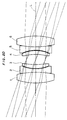
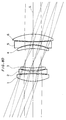
- Fig. 1 is a block diagram showing an embodiment of an apochromat optical system according to the present invention.
- the apochromat optical system is formed by a positive lens having a positive power (hereinafter referred to as "first lens") 1 whose convex surface 1a is directed to an object side (left-hand side in the figure), a negative lens having a negative power (hereinafter referred to as "second lens") 2 which is adjacent to the first lens 1 and having a concave surface 2a directed toward a stop 10, a positive lens in the form of meniscus having a positive power (hereinafter referred to as "third lens") 3 which is adjacent to the second lens 2 and having a convex surface 3a directed to the object side, a positive lens in the form of meniscus having a positive power (hereinafter referred to as "fourth lens”) 4 which is opposed to the third lens 3 through the stop 10 and having a convex surface 4a directed to an image-formation side (right-hand direction in the figure), a negative lens
- first lens
- the first to sixth lenses 1 to 6 satisfy the following conditions:
- n1, n2, n3, n4, n5 and n6 denote indexes of refraction of the first to sixth lenses 1 to 6, respectively, while symbols ⁇ 1, ⁇ 2, ⁇ 3, ⁇ 4, ⁇ 5 and ⁇ 6 denote Abbe's numbers of the first to sixth lenses 1 to 6 respectively.
- An average index of refraction ⁇ (n1 + n3)/2 ⁇ of the positive lenses 1 and 3 and an average index of refraction ⁇ n4 + n6)/2 ⁇ of the positive lenses 4 and 6 must be greater than indexes of refraction n2 and n5 of the negative lenses 2 and 5, respectively, while the refractive index ratio of the average index of refraction of the positive lenses 1 and 3 to the index of refraction of the negative lens 2 and the refractive index ratio of the average index of refraction of the positive lenses 4 and 6 to the index of refraction of the negative lens 5, are set to be greater than 1.01 and less than 1.08, as shown in the expressions (1) and (3).
- the average Abbe's number ⁇ ( ⁇ 1 + ⁇ 3)/2 ⁇ of the positive lenses 1 and 3 and the average Abbe's number ⁇ ( ⁇ 4 + ⁇ 6)/2 ⁇ of the positive lenses 4 and 6 must be greater than the Abbe's numbers ⁇ 2 and ⁇ 5 of the negative lenses 2 and 5, so that the optical system having the structure shown in Fig. 1 performs as an apochromatic lens. This is because, if the expression (2) is not satisfied, the first to sixth lenses 1 to 6 are so increased in refractive power that aberration values of the respective lenses 1 to 6 cannot be excellently maintained.
- an Abbe's number ratio of an average Abbe's number of the positive lenses 1 and 3 to the Abbe's number of the negative lens 2 and an Abbe's number ratio of an average Abbe's number of the positive lenses 4 and 6 to the Abbe's number of the negative lens 5 are set to be less than 1.3, respectively. If the Abbe's number ratios exceed 1.3, the Abbe's numbers of the first, third, fourth and sixth lenses 1, 3, 4 and 6 are respectively increased, while there is only glass material having a low index of refraction in glass materials having a large Abbe's number. Thus, the expression (1) is not satisfied. Therefore, it is substantially necessary to set the aforementioned Abbe's number ratios to be less than 1.3.
- an average image field of short wavelength light curves in a plus direction and an average image field of long wavelength light curves in a minus direction with respect to an average image field of reference rays.
- an axial image point of the short wavelength light may be corrected in the minus direction and an axial image point of the long wavelength light may be corrected in the plus direction, respectively.
- practical axial image points are not those by paraxial rays, but circles of least confusion including spherical aberration define image points. Therefore, even if paraxial image points are varied with respective wavelengths, practical image points can be matched with respect to three wavelengths by following spherical aberration of short wavelength light curves in a plus side as compared with that of reference wavelength light and spherical aberration of long wavelength light curves in a minus side as compared with that of the reference wavelength light so that spherical aberration values of zonal rays can be matched.
- the index of refraction n3 of the third lens 3 is higher than the index of refraction n2 of the second lens 2 and the index of refraction n4 of the fourth lens 4 is higher than the index of refraction n5 of the fifth lens 5.
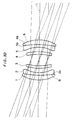
- First to sixth lenses 1 to 6 shown in Table 5 are combined in the aforementioned manner, to form an apochromatic lens (see Fig. 2D).
- the focal length f , the total field angle 2 ⁇ , the F-number F and the magnification M of this apochromatic lens are respectively set as shown in Table 6.
- All of the radii of curvature R1 to R12, the thickness values d1 to d6, spacing values d12 to d56 and the focal length f are in units of millimeters. This also applies to the following description.
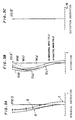
- Figs. 2A, 2B, 2C and 2D illustrate spherical aberration, astigmatism and distortion aberration of the apochromatic lens having the aforementioned structure and optical paths of light directed from the object side to the image-formation side, respectively.
- the results shown in Figs. 2A to 2D have been obtained through computer simulation on the basis of the above data.
- the horizontal axis represents aberration values and the vertical axis represents F numbers.
- the horizontal axis represent aberration values and the vertical axis represents the field angles.
- Solid lines in Fig. 2B show astigmatism values of sagital image fields, and dotted lines show those of meridional image fields.
- the horizontal axis represent aberration values and the vertical axis represents the field angles.
- symbols c , d and g denote simulation results as to lines c , d and g , respectively.
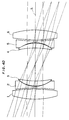
- First to sixth lens 1 to 6 shown in Table 7 are combined in the aforementioned manner, to form an apochromatic lens (see Fig. 3D).
- the focal length f , the total field angle 2 ⁇ , the F-number F and the magnification M of this apochromatic lens are respectively set as shown in Table 8.
- Radii of curvature R1 to R12, the thickness values d1 to d6 and lens spacing values d12 to d56 of the first to sixth lenses 1 to 6 are respectively set as shown in Table 9.
- Figs. 3A, 3B, 3C and 3D illustrate spherical aberration, astigmatism and distortion aberration of this apochromatic lens and optical paths of light directed from an object side to an image-formation side, respectively.
- First to sixth lenses 1 to 6 shown in Table 10 are combined in the aforementioned manner, to form an apochromatic lens (see Fig. 4D).
- the focal length f , the total field angle 2 ⁇ , the F-number F and the magnification M of this apochromatic lens are respectively set as shown in Table 11.
- Radii of curvature R1 to R12, thickness values d1 to d6 and lens spacing values d12 to d56 of the first to sixth lenses 1 to 6 are respectively set as shown in Table 12.
- Figs. 4A, 4B, 4C and 4D illustrates spherical aberration, astigmatism and distortion aberration of this apochromatic lens and optical paths of light directed from an object side to an image-formation side, respectively.
- First to sixth lenses 1 to 6 shown in Table 13 are combined in the aforementioned manner, to form an apochromatic lens (see Fig. 5D).
- the focal length f , the total field angle 2 ⁇ , the F-number F and the magnification M of this apochromatic lens are respectively set as shown in Table 14.
- Radii of curvature R1 to R12, lens thickness values d1 to d6 and lens spacing values d12 and d56 of the first to sixth lenses 1 to 6 are respectively set as shown in Table 15.
- Figs. 5A, 5B, 5C and 5D have been obtained through computer simulation on the basis of the above data.
- Figs. 5A, 5B, 5C and 5D illustrate spherical aberration, astigmatism and distortion aberration of this apochromatic lens and optical paths of light directed from an object side to an image-formation side, respectively.
- First to sixth lenses 1 to 6 shown in Table 16 are combined in the aforementioned manner, to form anapochromatic lens (see Fig. 6D).
- the focal length f , the total field angle 2 ⁇ , the F-number F and the magnification M of this apochromatic lens are respectively set as shown in Table 17.
- Radii of curvature R1 to R12, lens thickness values d1 to d6 and lens spacing values d12 to d56 of the first to sixth lenses 1 to 6 are respectively set as shown in Table 18.
- Figs. 6A, 6B, 6C and 6D illustrate spherical aberration, astigmatism and distortion aberration of this apochromatic lens and optical paths of light directed from an object side to an image-formation side respectively.
- First to sixth lenses 1 to 6 shown in Table 19 are combined in the aforementioned manner, to form an apochromatic lens (see Fig. 7D).
- the focal length f , the total field angle 2 ⁇ , the F-number F and the magnification M of this apochromatic lens are respectively set as shown in Table 20.
- Radii of curvature R1 to R12, lens thickness values d1 to d6 and lens spacing values d12 to d56 of the first to sixth lenses 1 to 6 are respectively set as shown in Table 21.
- Figs. 7A, 7B, 7C and 7D have been obtained through computer simulation on the basis of the above data.
- Figs. 7A, 7B, 7C and 7D illustrate spherical aberration, astigmatism and distortion aberration of this apochromatic lens and optical paths of light directed from an object side to an image-formation side, respectively.
- Example 6 is so formed as to automatically set lens spacing values d23 and d45 by bringing outer peripheral edges of the third and fourth lenses 3 and 4 into close contact with the second and fifth lenses 2 and 5, respectively.
- First to sixth lenses 1 to 6 are made of glass materials identical to those in Example 6, while the magnification of the apochromatic lens is halved as compared with that in Example 6.
- the lenses 1 to 6 are not completely symmetrical with respect to a stop 10 dissimilarly to Examples 1 to 6, but radii of curvature R1 to R12, lens thickness values d1 to d6 and lens spacing values d12 to d56 differ from each other between a front group (first to third lenses 1 to 3) and a rear group (fourth to sixth lenses 4 to 6) with respect to the stop 10.
- the first to sixth lenses 1 to 6 shown in Table 19 are combined in the aforementioned manner, to form the apochromatic lens (see Fig. 8D).
- the focal length f , the total field angle 2 ⁇ , the F-number F and the magnification M of this apochromatic lens are respectively set as shown in Table 22.
- the radii of curvature R1 to R12, the lens thickness values d1 to d6 and the lens spacing values d12 to d56 of the first to sixth lenses 1 to 6 are respectively set as shown in Table 23.
- Figs. 8A, 8B, 8C and 8D illustrate spherical aberration, astigmatism and distortion aberration of the apochromatic lens and optical paths of light directed from an object side to an image-formation side, respectively.
- First to sixth lenses 1 to 6 are made of glass materials identical to those in Example 6, and the magnification M of the apochromatic lens is doubled as compared with that in Example 6.
- radii of curvature R1 to R12, lens thickness values d1 to d6 and lens spacing values d12 to d56 differ from each other between a front group (first to third lenses 1 to 3) and a rear group (fourth to sixth lenses 4 to 6) with respect to a stop 10, similarly to Example 7.
- the first to sixth lenses 1 to 6 shown in Table 19 are combined in the aforementioned manner, to form the apochromatic lens (see Fig. 9D).
- the focal length f , the total field angle 2 ⁇ , the F-number and the magnification M of this apochromatic lens are respectively set as shown in Table 24.
- the radii of curvature R1 to R12 the lens thickness values d1 to d6 and the lens spacing values d12 to d56 of the first to sixth lenses are respectively set as shown in Table 25.
- Figs. 9A, 9B, 9C and 9D illustrate spherical aberration, astigmatism and distortion aberration of the apochromatic lens and optical paths of light directed from an object side to an image-formation side, respectively.
- the apochromatic lens of Example 9 is not completely symmetrical dissimilarly to Examples 1 to 6, but first and sixth lenses 1 and 6 and third and fourth lenses 3 and 4 are different in index of refraction n d , Abbe's number ⁇ d and partial dispersion ratio P g,F from each other, respectively. That is, first to sixth lenses 1 to 6 shown in Table 26 are combined in the aforementioned manner, to form the apochromatic lens (see Fig. 10D).
- the focal length f , the total field angle 2 ⁇ , the F-number F and the magnification M of this apochromatic lens are respectively set as shown in Table 27.
- Radii of curvature R1 to R12, lens thickness values d1 to d6 and lens spacing values d12 to d56 of the first to sixth lenses 1 to 6 are respectively set as shown in Table 28.
- Figs. 10A, 10B, 10C and 10D have been obtained through computer simulation on the basis of the above data.
- Figs. 10A, 10B, 10C and 10D illustrate spherical aberration, astigmatism and distortion aberration of this apochromatic lens and optical paths of light directed from an object side to an image-formation side, respectively.
- Fig. 11 is a perspective view showing an apparatus for color reproduction (hereinafter referred to as "copying apparatus") to which the aforementioned apochromatic lens is applied
- Fig. 12 is a schematic block diagram of the copying apparatus.
- the copying apparatus is formed by a main frame 108, an original scanning part 100 for feeding an original 501 in a direction E, an optical part 300 for applying light onto the original 501 and guiding reflected light to a recording part as hereinafter described, a recording part 200 for recording an image 502 of the original 501 on a copying paper 503 and a control part 400 for controlling the entire apparatus.
- Fig. 13 is a sectional view taken along line II -II in Fig. 11.
- the original scanning part 100 has a large number of feed rollers 112, which are rotated by a motor 120 to feed the original 501 in the direction E (Fig. 12).
- the feed rollers 112 rotated, the original 501 is fed between an original glass plate 144 and an original cover plate 145 for preventing floating of the original 501 and then discharged onto an original receiving tray 124, which is provided in a front upper side of the copying apparatus, through a discharge path 125.
- the original 501 is formed by a relatively thick sheet material and it is inconvenient to bend the same, the original 501 is discharged to another original receiving tray 127 through another discharge path 126 extending in a rear portion of this copying apparatus.
- a detector 122 is provided in a prescribed position in order to detect whether or not the original 501 is present on a feed path 121 for the original 501.
- An original repeating part 150 is opposed to the original glass plate 144 in order to record a plurality of identical images 502 of the same original 501.
- the original repeating part 150 is adapted to move the original 501 between the original glass plate 144 and the original cover plate 145 by a required number of times.
- the optical part 300 is provided with an illuminating part 140 which is formed by a pair of light sources 141 and 142 and a glass member 143, which prevents heat from transferring to the original scanning part 100.
- the illuminating part 140 projects light, which is applied onto the original 501 placed on the original glass plate 144.
- reflected light reflected by the original 501 is guided to the recording part 200 through a mirror 101, an apochromatic lens 103 and another mirror 102.
- the apochromatic lens 103 is movable between the mirrors 101 and 102 by a motor 109, and also movable in a direction perpendicular to the plane of Fig. 12 by another means (not shown).
- the structure of the apochromatic lens 103 is similar to that shown in Fig. 1, and hence redundant description is omitted.
- the mirrors 101 and 102 and the apochromatic lens 103 are supported by an optical bench 106.
- This optical bench 106 is supported by a base frame 107, and is vertically movable with respect to the base frame 107 by a motor 110.
- the base frame 107 is placed on the main frame 108, to be movable in a direction parallel to the direction of movement of the apochromatic lens 103.
- Fig. 14 is a sectional view taken along line III III in Fig. 11.
- a charger 202, a discharger 203, an exposure part 204, a toner developer 205, a paper feeding part 206, a toner transferor 207, a separator 208 for separating the copying paper 503 from a photosensitive drum 201, another discharger 209, a cleaner 210 and still another discharger 211 are sequentially provided around the photosensitive drum 201.
- a plurality of roll-type copying papers 503a which are different in width from each other, are prepared in the paper feeding part 206 to allow appropriate selection of the copying paper 503, while a cutter 215 is provided in a prescribed position to cut the copying papers 503a in response to required length. Further, a manual feeding path 216 is separately provided in order to feed a sheet-type copying paper 503b at need.
- an endless bent 217 and a fan 218 are provided in correspondence to the separator 208, in order to eject the copying paper 503 separated from the photosensitive drum 201 by the separator 208 to a prescribed position.
- Numeral 219 denotes a heating device, which melts a toner and fixes image 502′ (Fig. 12) on the copying paper 503.
- control part 400 is formed by an operation panel 450 and control means 410 including a microcomputer, a memory and the like.
- the control means 410 is supplied with a command from an operator through the operation panel 450, as well as with a detection signal from a sensor provided in the copying apparatus.
- the control means 410 outputs control signals for conotrolling the respective parts of the copying apparatus on the basis of the signal and the command.
- Fig. 15 is a flow chart showing the operation of the copying apparatus.
- the memory provided in the control means 410 stores the said data.
- the motor 110 is driven to vertically move the optical bench 106 in response to a command from the control means 410, while the motor 109 is driven to horizontally move the apochromatic lens 103.
- setting of the magnification is completed.
- the operator sets the original 501 on the center of a table 130 in the original scanning part 100 to downwardly direct the image 502 (step S2).
- the detector 122 detects the forward end of the original 501, and control data are reset in the control means 410 (step S3).
- step S4 the operator supplies a start command to the control means 410 through the operation panel 450 (step S4), whereby the copying apparatus is controlled as follows, in response to the command from the control means 410:
- the motor 120 of the original scanning part 100 is driven to feed the original 501 by a prescribed amount (step S5).
- a motor 230 of the recording part 200 is also driven to feed the copying paper 503 by a feed roller 221 (step S6).
- a pulse generator 24 coupled to the feed roller 221 outputs pulse signals, which are sequentially counted by the control means 410.
- illumination light is applied to the original 501 and copying operation is started (step S7). That is, the original 501 is fed in the direction E to be exposed to the illumination light, while reflected light reflected by the original 501 is exposed on the photosensitive drum 201 through the mirror 101, the apochromatic lens 103 and the mirror 102.
- a latent image formed on the photosensitive drum 201 is visualized by the developer 205, and thereafter the toner image 502′ is recorded on the copying paper 503 by the toner transferor 207.
- the image 502 on the original 501 is sequentially copied on the copying paper 503.
- step S8 When the amount of feeding of the copying paper 503 reaches a constant value, driving of the recording part 200 is released to stop recording of the image 502. Further, the copying paper 503 is fed by a prescribed amount, and then feeding of the copying paper 503 is stopped. Then, the copying paper 503 is cut by the rotary cutter 215, to be discharged on a paper receiving tray 220. At the same time, the original 501 is also discharged on the original receiving tray 124, whereby the copying apparatus is stopped (step S8).
- the image 502 on the original 501 can be more clearly copied on the copying paper 503 by applying the aforementioned apochromatic lens to the copying apparatus.
- the copying apparatus is not restricted to this type but the apochromatic lens according to the present invention is applicable to all types of general copying apparatuses.
Landscapes
- Physics & Mathematics (AREA)
- Health & Medical Sciences (AREA)
- Toxicology (AREA)
- General Physics & Mathematics (AREA)
- Optics & Photonics (AREA)
- Lenses (AREA)
Claims (2)
- Ein apochromatisches optisches System, mit:
einem Anschlag (6), der entlang der optischen Achse des Systems vorgesehen ist;
einer ersten Linsengruppe, mit: einer ersten Linse (1) mit einer positiven Stärke, die eine konvexe Fläche, welche auf ein Objekt gerichtet ist, hat; einer zweiten Linse (2), deren Abbe-Zahl innerhalb des Bereiches von 45,0 bis 34,0 liegt, die eine negative Stärke hat und deren konkave Fläche auf ein Bild gerichtet ist; und einer dritten Linse (3) in der Form eines Meniskus mit einer positiven Stärke, die eine konvexe Fläche hat, welche auf das Objekt gerichtet ist, wobei die erste (1) bis dritte (3) Linse nacheinander in dieser Reihenfolge von der Objektseite des Systems aus angeordnet sind, und
einer zweiten Linsengruppe, mit im wesentlichen denselben Ausbildungen von Linsen wie diejenigen der ersten Gruppe, wobei die zweite Linsengruppe aufweist:
eine vierte Linse in der Form eines Meniskus mit einer positiven Stärke, wobei die vierte Linse eine konvexe Fläche hat, die auf die Bilder gerichtet ist,
eine fünfte Linse (5) mit einer Abbe-Zahl in dem Bereich von 45,0 bis 34,0, die eine negative Stärke hat und deren konkave Fläche auf das Objekt gerichtet ist; und einer sechsten Linse (6) mit einer konvexen Fläche, die auf das Bild gerichtet ist, wobei die vierte (4) bis sechste Linse (6) nacheinander in dieser Reihenfolge von dem Anschlag (6) aus angeordnet sind;
wobei die Linsen der ersten und der zweiten Linsengruppen annähernd symmetrisch bezüglich des Anschlags (6) sind;
und wobei die Linsen der ersten Linsengruppe die folgenden Bedingungen erfüllen:
n₃ > n₂
1.08 > {(n₁ + n₃)/2}/n₂ > 1,01
ν₁ > ν₂
ν₃ > ν₂
1,3 > {(ν₁ + ν₃)/ν₂ > 1,0 und
und wobei n₁, n₂, n₃ ein Refraktionsindex der ersten (1), zweiten (2) bzw. dritten (3) Linse sind; und »1, »2 und »3 eine Abbe-Zahl der ersten (1), der zweiten (2) bzw. der dritten (3) Linse sind;
und wobei die zweite Linsengruppe die nachfolgenden Bedingungen erfüllen:
n₄ > n₅
1.08 > {(n₄ + n₆)/2}/n₅ > 1,01
ν₄ > ν₅
ν₆ > ν₅ und
1,3 > {(ν₄ + ν₆)/2}/ν₅ > 1,0
wobei n₄, n₅ und n₆ ein Refraktionsindex der vierten (4), fünften (5) bzw. sechsten (6) Linse sind und »4, »5 und »6 eine Abbe-Zahl der vierten (4, fünften (5) und sechsten (6) Linse sind,
dadurch gekennzeichnet, daß
die zweite und die vierte Linse (2, 5) aus einem Kurzflint-Glas gefertigt sind. - Vorrichtung zur Farbreproduktion mit:
einer Lichtquelle (141, 142) zum Beleuchten einer zu reproduzierenden Vorlage;
einem Vorlagehalter (144) zum Halten einer Farbvorlage auf dieser;
fotoempfindlichen Mitteln (200) zum Reproduzieren eines Bildes auf der Vorlage bei Aufnehmen von Licht von der zu reproduzierenden Vorlage;
gekennzeichnet durch
ein apochromatisches optisches System nach Anspruch 1.
Applications Claiming Priority (2)
| Application Number | Priority Date | Filing Date | Title |
|---|---|---|---|
| JP109701/88 | 1988-05-02 | ||
| JP63109701A JPH01279218A (ja) | 1988-05-02 | 1988-05-02 | アポクロマート・レンズ |
Publications (3)
| Publication Number | Publication Date |
|---|---|
| EP0340647A2 EP0340647A2 (de) | 1989-11-08 |
| EP0340647A3 EP0340647A3 (de) | 1992-01-02 |
| EP0340647B1 true EP0340647B1 (de) | 1995-03-29 |
Family
ID=14517021
Family Applications (1)
| Application Number | Title | Priority Date | Filing Date |
|---|---|---|---|
| EP89107679A Expired - Lifetime EP0340647B1 (de) | 1988-05-02 | 1989-04-27 | Apochromatisches optisches System |
Country Status (4)
| Country | Link |
|---|---|
| US (1) | US4955701A (de) |
| EP (1) | EP0340647B1 (de) |
| JP (1) | JPH01279218A (de) |
| DE (1) | DE68921916T2 (de) |
Families Citing this family (13)
| Publication number | Priority date | Publication date | Assignee | Title |
|---|---|---|---|---|
| US5172275A (en) * | 1990-12-14 | 1992-12-15 | Eastman Kodak Company | Apochromatic relay lens systems suitable for use in a high definition telecine apparatus |
| US5258777A (en) * | 1991-08-23 | 1993-11-02 | Eastman Kodak Company | Thermal printer system with a high aperture micro relay lens system |
| US5272568A (en) * | 1991-12-11 | 1993-12-21 | Eastman Kodak Company | High aperture finite conjugate lens system |
| JPH06501792A (ja) * | 1991-08-23 | 1994-02-24 | イーストマン・コダック・カンパニー | マイクロリレーレンズとして使用するに適した高開口数の有限共役レンズ系及びそのレンズ系を用いたプリンタ |
| US5274503A (en) * | 1991-08-23 | 1993-12-28 | Eastman Kodak Company | High aperture finite conjugate lens system suitable for use as a micro relay lens |
| US5305138A (en) * | 1992-07-31 | 1994-04-19 | International Business Machines Corporation | Superachromatic UV and visible focusing objective lens |
| US5864436A (en) * | 1997-09-04 | 1999-01-26 | Raytheon Company | Constant deviation objective lens |
| JP4516475B2 (ja) * | 2005-04-27 | 2010-08-04 | オリンパスメディカルシステムズ株式会社 | 略球形状の観察窓を有する内視鏡用撮像光学系 |
| DE102008027414B4 (de) * | 2008-06-09 | 2013-03-28 | Astrium Gmbh | Apochromatisches Objektiv |
| DE102011102345B4 (de) * | 2011-05-25 | 2020-08-06 | Carl Zeiss Microscopy Gmbh | Apochromatischer Vorsatz für Zoomobjektive |
| TWI477808B (zh) * | 2014-01-17 | 2015-03-21 | Largan Precision Co Ltd | 攝影光學鏡頭、取像裝置及車用攝影裝置 |
| KR20180078217A (ko) * | 2018-07-02 | 2018-07-09 | 삼성전기주식회사 | 촬상 광학계 |
| CN113204097B (zh) * | 2021-05-08 | 2022-10-04 | 浙江舜宇光学有限公司 | 光学摄像镜头 |
Family Cites Families (24)
| Publication number | Priority date | Publication date | Assignee | Title |
|---|---|---|---|---|
| US3088371A (en) * | 1960-08-05 | 1963-05-07 | Gen Scientific Corp | Symmetrical six component photographic objective |
| DE2023861C3 (de) * | 1970-05-15 | 1974-04-04 | Wilhelm Will Kg, Optisches Werk, 6331 Nauborn | Achromat-Objektiv |
| US3687522A (en) * | 1971-02-01 | 1972-08-29 | Ilex Optical Co Inc | Variable magnification lens system for finite conjugate distances |
| US3672748A (en) * | 1971-05-14 | 1972-06-27 | Xerox Corp | Split dagor-type of symmetrical copying lens system |
| JPS5110091B2 (de) * | 1972-06-20 | 1976-04-01 | ||
| JPS50145225A (de) * | 1974-05-13 | 1975-11-21 | ||
| JPS5378838A (en) * | 1976-12-22 | 1978-07-12 | Konishiroku Photo Ind Co Ltd | Wide-angle lens of symmetrical type |
| JPS55159410A (en) * | 1979-05-30 | 1980-12-11 | Ricoh Co Ltd | Compact copying lens of high aperture efficiency |
| JPS6051092B2 (ja) * | 1980-05-09 | 1985-11-12 | 株式会社リコー | 複写用レンズ |
| US4349249A (en) * | 1980-05-21 | 1982-09-14 | The United States Of America As Represented By The United States Department Of Energy | Compound lens |
| JPS5714811A (en) * | 1980-07-01 | 1982-01-26 | Canon Inc | Lens for copying machine |
| JPS5748708A (en) * | 1980-09-09 | 1982-03-20 | Ricoh Co Ltd | Reflex objective lens |
| JPS5872116A (ja) * | 1981-10-23 | 1983-04-30 | Ricoh Co Ltd | 開口効率の大きい広角複写レンズ |
| EP0106471B1 (de) * | 1982-09-20 | 1990-02-28 | LOCKHEED MISSILES & SPACE COMPANY, INC. | Verfahren zur Auswahl optischer Materialien |
| JPS6095511A (ja) * | 1983-10-31 | 1985-05-28 | Ricoh Co Ltd | 複写用レンズ |
| JPS60111214A (ja) * | 1983-11-21 | 1985-06-17 | Ricoh Co Ltd | 複写用レンズ |
| JPS60149017A (ja) * | 1984-01-14 | 1985-08-06 | Asahi Optical Co Ltd | 複写用レンズ |
| JPS619671A (ja) * | 1984-06-25 | 1986-01-17 | Dainippon Screen Mfg Co Ltd | 電子写真複写機における複写画像の部分撮り方法およびそのための装置 |
| JPS6143713A (ja) * | 1984-08-08 | 1986-03-03 | Ricoh Co Ltd | 複写用レンズ系 |
| JPS61196203A (ja) * | 1985-02-26 | 1986-08-30 | Erumoshiya:Kk | 照度補正光学系 |
| JPS6214110A (ja) * | 1985-07-11 | 1987-01-22 | Ricoh Co Ltd | 複写用レンズ |
| JPS62105113A (ja) * | 1985-10-31 | 1987-05-15 | Tokyo Optical Co Ltd | 変倍光学系 |
| JPS63186329A (ja) * | 1987-01-28 | 1988-08-01 | Nec Corp | 三角関数前処理装置 |
| JPS63186206A (ja) * | 1987-01-29 | 1988-08-01 | Ricoh Co Ltd | 複写機用レンズ |
-
1988
- 1988-05-02 JP JP63109701A patent/JPH01279218A/ja active Pending
-
1989
- 1989-04-27 DE DE68921916T patent/DE68921916T2/de not_active Expired - Fee Related
- 1989-04-27 EP EP89107679A patent/EP0340647B1/de not_active Expired - Lifetime
- 1989-05-01 US US07/345,482 patent/US4955701A/en not_active Expired - Fee Related
Also Published As
| Publication number | Publication date |
|---|---|
| DE68921916D1 (de) | 1995-05-04 |
| DE68921916T2 (de) | 1995-07-27 |
| JPH01279218A (ja) | 1989-11-09 |
| EP0340647A3 (de) | 1992-01-02 |
| EP0340647A2 (de) | 1989-11-08 |
| US4955701A (en) | 1990-09-11 |
Similar Documents
| Publication | Publication Date | Title |
|---|---|---|
| EP0340647B1 (de) | Apochromatisches optisches System | |
| EP0549146B1 (de) | Zoomobjektiv mit refraktiven und diffraktiven optischen Elementen | |
| JP3103166B2 (ja) | 射出瞳の遠いマクロレンズ | |
| US5726809A (en) | Camera system and an optical adapter to reduce image format size | |
| US7884979B2 (en) | Imaging lens, image reader using the lens, and imaging apparatus using the image reader | |
| US7446953B2 (en) | Imaging lens, image reading apparatus and image forming apparatus | |
| JP2002082282A (ja) | 原稿読取レンズ・原稿読取レンズユニット・原稿読取モジュール・原稿読取方法・原稿読取装置・画像情報処理装置 | |
| US7450275B2 (en) | Document reading lens, document reading lens unit, document reader, and image forming apparatus | |
| JP3640366B2 (ja) | ズームレンズ | |
| JPH0348807A (ja) | ズームレンズ | |
| US4790638A (en) | Lens system for projecting images of microfilm | |
| JPH08510567A (ja) | 可変イメージスケール付き光学系 | |
| JP2008076558A (ja) | 画像読取レンズおよび画像読取装置および画像形成装置 | |
| WO1992021054A1 (en) | Real image zoom viewfinder | |
| JP2001272600A (ja) | テレコンバータレンズ | |
| JP2000111795A (ja) | 複写用レンズ及びそれを用いた画像複写装置 | |
| JPH05323192A (ja) | 可変焦点距離レンズ | |
| US5255123A (en) | Microfilm reader/printer zoom lens system | |
| JPH0519164A (ja) | ズームレンズ | |
| JP2000162499A (ja) | 結像レンズ系および記録光学装置 | |
| US4878744A (en) | Three dimensional reflex lens systems | |
| JPH0575718U (ja) | クローズアップレンズ付きズームレンズ | |
| JP3000462B2 (ja) | 切換え式3焦点光学系 | |
| KR100254270B1 (ko) | 실물화상기용마이크로스코프광학계 | |
| JPH05508250A (ja) | 改善された視野マスクを備える光学装置 |
Legal Events
| Date | Code | Title | Description |
|---|---|---|---|
| PUAI | Public reference made under article 153(3) epc to a published international application that has entered the european phase |
Free format text: ORIGINAL CODE: 0009012 |
|
| AK | Designated contracting states |
Kind code of ref document: A2 Designated state(s): DE FR GB |
|
| PUAL | Search report despatched |
Free format text: ORIGINAL CODE: 0009013 |
|
| AK | Designated contracting states |
Kind code of ref document: A3 Designated state(s): DE FR GB |
|
| 17P | Request for examination filed |
Effective date: 19920604 |
|
| 17Q | First examination report despatched |
Effective date: 19931229 |
|
| GRAA | (expected) grant |
Free format text: ORIGINAL CODE: 0009210 |
|
| AK | Designated contracting states |
Kind code of ref document: B1 Designated state(s): DE FR GB |
|
| PG25 | Lapsed in a contracting state [announced via postgrant information from national office to epo] |
Ref country code: FR Effective date: 19950329 |
|
| REF | Corresponds to: |
Ref document number: 68921916 Country of ref document: DE Date of ref document: 19950504 |
|
| EN | Fr: translation not filed | ||
| PLBE | No opposition filed within time limit |
Free format text: ORIGINAL CODE: 0009261 |
|
| STAA | Information on the status of an ep patent application or granted ep patent |
Free format text: STATUS: NO OPPOSITION FILED WITHIN TIME LIMIT |
|
| 26N | No opposition filed | ||
| PGFP | Annual fee paid to national office [announced via postgrant information from national office to epo] |
Ref country code: GB Payment date: 19980420 Year of fee payment: 10 |
|
| PGFP | Annual fee paid to national office [announced via postgrant information from national office to epo] |
Ref country code: DE Payment date: 19980504 Year of fee payment: 10 |
|
| PG25 | Lapsed in a contracting state [announced via postgrant information from national office to epo] |
Ref country code: GB Free format text: LAPSE BECAUSE OF NON-PAYMENT OF DUE FEES Effective date: 19990427 |
|
| GBPC | Gb: european patent ceased through non-payment of renewal fee |
Effective date: 19990427 |
|
| PG25 | Lapsed in a contracting state [announced via postgrant information from national office to epo] |
Ref country code: DE Free format text: LAPSE BECAUSE OF NON-PAYMENT OF DUE FEES Effective date: 20000201 |