EP0326052A2 - Procédé de fabrication d'un joint d'étanchéité entre deux chambres sous pression - Google Patents
Procédé de fabrication d'un joint d'étanchéité entre deux chambres sous pression Download PDFInfo
- Publication number
- EP0326052A2 EP0326052A2 EP89101075A EP89101075A EP0326052A2 EP 0326052 A2 EP0326052 A2 EP 0326052A2 EP 89101075 A EP89101075 A EP 89101075A EP 89101075 A EP89101075 A EP 89101075A EP 0326052 A2 EP0326052 A2 EP 0326052A2
- Authority
- EP
- European Patent Office
- Prior art keywords
- inner body
- outer body
- chamber pressure
- opening
- pressure pack
- Prior art date
- Legal status (The legal status is an assumption and is not a legal conclusion. Google has not performed a legal analysis and makes no representation as to the accuracy of the status listed.)
- Granted
Links
Images
Classifications
-
- B—PERFORMING OPERATIONS; TRANSPORTING
- B65—CONVEYING; PACKING; STORING; HANDLING THIN OR FILAMENTARY MATERIAL
- B65D—CONTAINERS FOR STORAGE OR TRANSPORT OF ARTICLES OR MATERIALS, e.g. BAGS, BARRELS, BOTTLES, BOXES, CANS, CARTONS, CRATES, DRUMS, JARS, TANKS, HOPPERS, FORWARDING CONTAINERS; ACCESSORIES, CLOSURES, OR FITTINGS THEREFOR; PACKAGING ELEMENTS; PACKAGES
- B65D83/00—Containers or packages with special means for dispensing contents
- B65D83/14—Containers for dispensing liquid or semi-liquid contents by internal gaseous pressure, i.e. aerosol containers comprising propellant
- B65D83/60—Containers for dispensing liquid or semi-liquid contents by internal gaseous pressure, i.e. aerosol containers comprising propellant with contents and propellant separated
- B65D83/62—Containers for dispensing liquid or semi-liquid contents by internal gaseous pressure, i.e. aerosol containers comprising propellant with contents and propellant separated by membranes, bags or the like
-
- B—PERFORMING OPERATIONS; TRANSPORTING
- B21—MECHANICAL METAL-WORKING WITHOUT ESSENTIALLY REMOVING MATERIAL; PUNCHING METAL
- B21D—WORKING OR PROCESSING OF SHEET METAL OR METAL TUBES, RODS OR PROFILES WITHOUT ESSENTIALLY REMOVING MATERIAL; PUNCHING METAL
- B21D51/00—Making hollow objects
- B21D51/16—Making hollow objects characterised by the use of the objects
- B21D51/24—Making hollow objects characterised by the use of the objects high-pressure containers, e.g. boilers, bottles
-
- B—PERFORMING OPERATIONS; TRANSPORTING
- B21—MECHANICAL METAL-WORKING WITHOUT ESSENTIALLY REMOVING MATERIAL; PUNCHING METAL
- B21D—WORKING OR PROCESSING OF SHEET METAL OR METAL TUBES, RODS OR PROFILES WITHOUT ESSENTIALLY REMOVING MATERIAL; PUNCHING METAL
- B21D51/00—Making hollow objects
- B21D51/16—Making hollow objects characterised by the use of the objects
- B21D51/26—Making hollow objects characterised by the use of the objects cans or tins; Closing same in a permanent manner
- B21D51/2615—Edge treatment of cans or tins
- B21D51/2623—Curling
-
- B—PERFORMING OPERATIONS; TRANSPORTING
- B21—MECHANICAL METAL-WORKING WITHOUT ESSENTIALLY REMOVING MATERIAL; PUNCHING METAL
- B21D—WORKING OR PROCESSING OF SHEET METAL OR METAL TUBES, RODS OR PROFILES WITHOUT ESSENTIALLY REMOVING MATERIAL; PUNCHING METAL
- B21D51/00—Making hollow objects
- B21D51/16—Making hollow objects characterised by the use of the objects
- B21D51/26—Making hollow objects characterised by the use of the objects cans or tins; Closing same in a permanent manner
- B21D51/2615—Edge treatment of cans or tins
- B21D51/2638—Necking
Definitions
- the invention relates to a method for producing a two-chamber pressure pack with an outer body, which encloses a pressurizable interior and forms an opening through which an inner body made of fold-forming or crushable material is used.
- Such two-chamber pressure packs are generally used today as a replacement for the known pressure containers with propellant gas.
- the medium is discharged from the inner body by pressurizing the interior of the outer body.
- the medium to be dispensed therefore does not come into contact with this pressure medium, but is expressed by changing the inner body through a valve.
- These known two-chamber pressure packs consist essentially of three parts, namely the outer body, for example an aluminum sleeve with a bottom, the inner body, for example a very thin aluminum sleeve and a funnel, which is placed on the mouth edge of the inner and outer body and surrounds it in a sealing manner. The corresponding valve is then inserted in the center of this disk-shaped funnel.
- Attaching the funnel to the mouth edges of the inner and outer body means a considerable amount of work, since this has to be done by hand.
- the funnel is rolled or flanged together with the mouth edges. That is why he needs a certain place. Since the valve itself usually also requires a diameter of 25 mm, the openings of today's two-chamber pressure packs must have a total diameter of around 40-65 mm. In between, only two-chamber pressure packs with graduated dimensions are used.
- the inventor has set itself the goal of developing a method of the type mentioned above, by means of which the attachment of the additional funnel becomes superfluous, in which the interior of the outer body can be kept absolutely tight and in which two-chamber pressure packs with different opening diameters from 1 Customs, d. H. can be produced from 25.4 mm.
- the outer body and inner body are connected to one another in a predetermined area before flanging or the like.
- connection is preferably made by welding, gluing, shaping or the like.
- a coating has proven to be the best here, which is applied either to the outer body or to the inner body or to both in the connection region before the inner body is inserted into the outer body.
- This coating for example a suitable adhesive, can then dry so that the inner body is inserted into the outer body without changing the coating.
- the two-chamber pressure pack preferably passes through an oven in which the coating is liquefied. This already creates a certain connection between the inner body and the outer body.
- the inner body since the inner body generally maintains a certain distance from the outer body in order to be surrounded by sufficient pressure medium in the position of use, it has proven to be advisable to insert a tool into the opening of the two-chamber pressure pack, via which the inner body in the corresponding connection area is pressed against the outer body.
- This tool can be heated so that the coating is liquefied or kept in motion by this heat.
- the mouth edges are then flanged, this preferably being done by rolling.
- the two-chamber pressure pack now only needs to be filled with the medium to be dispensed and the valve put on, through which the space of the inner body is now sealed, and the propellant gas has to be supplied via a bottom hole.
- This method according to the invention also has the advantage that both the outer body and the inner body can be printed, varnished or the like before the flanging.
- all standard interior protective lacquers can be used.
- the flanging can be done by means of an automatic machine, so that considerable labor is saved.
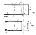
- a two-chamber pressure pack P has a sleeve-shaped outer body 1, which in the present exemplary embodiment essentially consists of a cylinder jacket 2 and a base cover 3.
- This outer body 1 can, for example, be produced from an aluminum blank in the extrusion or deep-drawing process.
- the bottom cover 3 has a bore 4 through which the interior I can be pressurized. After this process, the bore 4 can be closed.
- An inner body 6 is inserted into a cylinder opening 5 beyond the bottom cover 3 of the outer body 1.
- This inner body 6 also has a cylinder jacket 7 and a closed bottom cover 8.
- this inner body 6 consists of a relatively thin aluminum, so that it can be crushed with the formation of folds.
- Cylinder jacket 7 and base cover 8 enclose a space R, which in the position of use serves to receive a medium to be dispensed.
- the inner body 6 maintains a distance a from the cylinder jacket 2 of the outer body 1 over long distances.
- inner body 6 or its cylinder jacket 7 is connected to cylinder jacket 2 in area b.
- the connection is made, for example, by welding, gluing, laser welding, shaping or the like.
- This preliminary stage of a two-chamber pressure pack according to the invention is produced as follows:
- the outer body 1 is drawn from an aluminum blank.
- the hole 4 is made in the bottom cover 3 and the cylinder jacket 2 is covered or welded with a coating 9 of an adhesive over the region b.
- the inner body 6 is inserted, the coating 9 being solidified so that it does not hinder insertion.
- the two-chamber pressure pack P now passes through an oven in which the coating 9 is liquefied. As a result, a connection between cylinder jacket 2 and cylinder jacket 7 is already initiated. However, the correct connection produces a heated tool which is inserted through the cylinder opening 5 and presses the cylinder jacket 7 in region b against the cylinder jacket 2.
- the next processing stage is shown in FIG. 2.
- the bottom cover 3 is deformed so that it can withstand an internal pressure in the interior I and does not bulge.
- cylinder jacket 2 and cylinder jacket 7 are flanged outwards in the region of the cylinder opening 5, so that a flanged edge 10 is created.
- cylinder jacket 2 and cylinder jacket 7 are simultaneously pulled inwards in a specific area.
- the space R of the inner body 6 is now filled with the substance to be dispensed and the cylinder opening 5 is closed by a cover with a valve, not shown. This lid seals the flange 10.
- the interior I of the outer body 1 is then pressurized through the bore 4, the bore 4 then being closed.
- the inner body 6 is pressurized, so that when the valve is actuated, the medium is discharged from the space R of the inner body 6 through the valve, while the inner body 6 yields to the same extent to the pressure in the interior of the outer body 1 and crumples .
Landscapes
- Engineering & Computer Science (AREA)
- Mechanical Engineering (AREA)
- Chemical & Material Sciences (AREA)
- Dispersion Chemistry (AREA)
- Containers And Packaging Bodies Having A Special Means To Remove Contents (AREA)
- Gasket Seals (AREA)
- Filling Or Discharging Of Gas Storage Vessels (AREA)
- Auxiliary Devices For And Details Of Packaging Control (AREA)
- Nozzles (AREA)
- Joining Of Glass To Other Materials (AREA)
- Packages (AREA)
- Glass Compositions (AREA)
- Particle Formation And Scattering Control In Inkjet Printers (AREA)
- Crystals, And After-Treatments Of Crystals (AREA)
- Closures For Containers (AREA)
- Press Drives And Press Lines (AREA)
- Infusion, Injection, And Reservoir Apparatuses (AREA)
Priority Applications (1)
| Application Number | Priority Date | Filing Date | Title |
|---|---|---|---|
| AT89101075T ATE83953T1 (de) | 1988-01-27 | 1989-01-23 | Verfahren zum herstellen einer zweikammerdruckkammer. |
Applications Claiming Priority (2)
| Application Number | Priority Date | Filing Date | Title |
|---|---|---|---|
| DE3802314 | 1988-01-27 | ||
| DE3802314A DE3802314C1 (fr) | 1988-01-27 | 1988-01-27 |
Publications (3)
| Publication Number | Publication Date |
|---|---|
| EP0326052A2 true EP0326052A2 (fr) | 1989-08-02 |
| EP0326052A3 EP0326052A3 (en) | 1990-09-12 |
| EP0326052B1 EP0326052B1 (fr) | 1992-12-30 |
Family
ID=6346062
Family Applications (1)
| Application Number | Title | Priority Date | Filing Date |
|---|---|---|---|
| EP89101075A Expired - Lifetime EP0326052B1 (fr) | 1988-01-27 | 1989-01-23 | Procédé de fabrication d'un joint d'étanchéité entre deux chambres sous pression |
Country Status (18)
| Country | Link |
|---|---|
| US (1) | US5069590A (fr) |
| EP (1) | EP0326052B1 (fr) |
| JP (1) | JP2873691B2 (fr) |
| AT (1) | ATE83953T1 (fr) |
| AU (1) | AU617412B2 (fr) |
| BR (1) | BR8900323A (fr) |
| CA (1) | CA1316407C (fr) |
| DE (2) | DE3802314C1 (fr) |
| DK (1) | DK168589B1 (fr) |
| ES (1) | ES2037884T3 (fr) |
| FI (1) | FI94845C (fr) |
| GR (1) | GR3006763T3 (fr) |
| HK (1) | HK56593A (fr) |
| LT (1) | LT3830B (fr) |
| LV (1) | LV11055B (fr) |
| NO (1) | NO173646C (fr) |
| RU (1) | RU2027098C1 (fr) |
| ZA (1) | ZA89670B (fr) |
Cited By (11)
| Publication number | Priority date | Publication date | Assignee | Title |
|---|---|---|---|---|
| EP0547982A1 (fr) * | 1991-12-17 | 1993-06-23 | Cebal S.A. | Procédé de fabrication d'un corps de distributeur à poche en métal, corps de distributeur et distributeur correspondant |
| EP0743255A1 (fr) * | 1995-05-19 | 1996-11-20 | Gerd Stoffel | Procédé de fabrication d'un récipient sous pression à deux compartiments |
| EP0755877A1 (fr) * | 1995-07-28 | 1997-01-29 | IPC Packaging AG | Récipient à deux compartiments avec récipient interne conique |
| WO1999020543A1 (fr) * | 1997-10-17 | 1999-04-29 | Lechner Gmbh | Procede de production d'une bombe a aerosol presentant deux chambres, et dispositif pour mettre en oeuvre ledit procede |
| RU2131389C1 (ru) * | 1994-04-18 | 1999-06-10 | Герд Штоффель | Способ изготовления двухкамерной тары, в которой используется среда, находящаяся под давлением |
| WO1999059896A1 (fr) * | 1998-05-20 | 1999-11-25 | Cebal S.A. | Corps de distributeur sous pression ayant une poche metallique ou metalloplastique, ladite poche et son procede d'obtention |
| FR2820127A1 (fr) | 2001-01-30 | 2002-08-02 | Pechiney Emballage Alimentaire | Poche et boitier muni de cette poche permettant d'obtenir un distributeur a taux de restitution ameliore |
| EP1468759A1 (fr) * | 2003-04-15 | 2004-10-20 | Nussbaum Rielasingen GmbH | Procédé de fabrication d'un récipient sous pression à deux compartiments |
| DE102007050333A1 (de) | 2007-10-18 | 2009-04-23 | Nussbaum Rielasingen Gmbh | Verfahren zum Herstellen eines Zweikammerdruckbehälters |
| US10239648B2 (en) | 2014-10-28 | 2019-03-26 | Ball Metalpack, Llc | Apparatus and method for forming a cup with a reformed bottom |
| US10315242B2 (en) | 2014-10-15 | 2019-06-11 | Ball Metalpack, Llc | Apparatus and method for simultaneously forming a contoured shoulder and neck portion in a closed end of a metallic container |
Families Citing this family (19)
| Publication number | Priority date | Publication date | Assignee | Title |
|---|---|---|---|---|
| DE3915765C2 (de) * | 1988-01-27 | 1998-07-30 | Gerd Stoffel | Verfahren zum Herstellen einer Zweikammer-Druckpackung |
| DE4023602A1 (de) * | 1990-07-25 | 1992-01-30 | Majer Christian Gmbh Co Kg | Verbunddose, insbesondere zur verpackung von nahrungsmitteln |
| DE19746017C2 (de) * | 1997-10-17 | 2000-12-21 | Lechner Gmbh | Verfahren und Vorrichtung zur Herstellung einer Zweikammerdruckpackung |
| EP1059129A3 (fr) * | 1999-06-10 | 2001-09-26 | LECHNER GmbH, Fabrik für Aluminium-Verpackungen | Méthode et dispositif pour la fabrication d' une bombe à aérosol comportant deux chambres, outil de formage utilisé dans cette méthode et ce dispositif et bombe à aérosol ainsi fabriquée |
| DE19932680C2 (de) * | 1999-06-10 | 2001-07-26 | Lechner Gmbh | Verfahren und Vorrichtung zur Herstellung einer Zweikammerdruckpackung |
| DE10017021B4 (de) * | 2000-04-05 | 2008-10-16 | Linnemann-Schnetzer Gmbh | Verfahren zur Herstellung eines Behälters zur Aufnahme eines unter Druck stehenden Mediums sowie Druckbehälter |
| DE10207129B4 (de) * | 2002-02-20 | 2004-04-01 | Lechner Gmbh | Verfahren und Vorrichtung zum Herstellen eines Druckpackungsbehälters |
| DE10222749B4 (de) * | 2002-05-23 | 2009-04-02 | Hilti Aktiengesellschaft | Druckbehälter |
| EP1422052B1 (fr) * | 2002-11-20 | 2009-05-13 | Joaquin Devesa Company | Procédé de fabrication d'un récipient cylindrique multi-couches et récipient ainsi obtenu |
| DE10318576B3 (de) | 2003-04-24 | 2004-11-25 | Hilti Ag | Druckbehälter und Verfahren zum Herstellen und/oder Befüllen eines Druckbehälters |
| DE10321765B4 (de) * | 2003-05-15 | 2007-10-11 | Hilti Ag | Verfahren zum Herstellen und Befüllen eines Druckbehälters und Druckbehälter |
| DE10326474B4 (de) * | 2003-06-12 | 2008-04-17 | Hilti Ag | Druckbehälter |
| FR2884894B1 (fr) * | 2005-04-22 | 2007-06-29 | Prospection Et D Inv S Techniq | Cartouche de gaz de combustion pour appareil de fixation a gaz |
| JP5103871B2 (ja) | 2006-01-27 | 2012-12-19 | マックス株式会社 | ガスカートリッジ |
| JP5223186B2 (ja) | 2006-01-27 | 2013-06-26 | マックス株式会社 | ガスカートリッジ |
| JP4877504B2 (ja) | 2006-01-27 | 2012-02-15 | マックス株式会社 | ガスカートリッジ |
| DE102007062471A1 (de) | 2007-12-20 | 2009-06-25 | Krones Ag | Vorrichtung und Verfahren zum Aufbringen von Etiketten |
| RU2449206C1 (ru) * | 2010-09-03 | 2012-04-27 | Открытое акционерное общество "Газпром" | Двуполостной сосуд давления с изменяющимся объемом полостей |
| WO2017055786A1 (fr) * | 2015-10-01 | 2017-04-06 | Presspart Manufacturing Limited | Cartouche et enveloppe d'inhalateur de dose mesurée |
Family Cites Families (9)
| Publication number | Priority date | Publication date | Assignee | Title |
|---|---|---|---|---|
| FR2140804A5 (fr) * | 1971-06-08 | 1973-01-19 | Scal Gp Condit Aluminium | |
| US3974945A (en) * | 1975-01-27 | 1976-08-17 | Norman D. Burger | Aerosol dispensing system |
| GB1508509A (en) * | 1975-05-07 | 1978-04-26 | Cebal | Pressurized dispensing container of the type having an inner flexible container and method for manufacturing same |
| FR2310287A1 (fr) * | 1975-05-07 | 1976-12-03 | Cebal | Procede et appareillage pour obtenir l'etancheite de recipients dits aerosols a poche |
| SE404346B (sv) * | 1976-02-27 | 1978-10-02 | Rhenag Ag | Kerl for upptagning och avgivning av flytande och pastaformiga massor under tryck |
| US4308973A (en) * | 1978-06-30 | 1982-01-05 | The Continental Group, Inc. | Compartmented aerosol container |
| US4185758A (en) * | 1978-08-01 | 1980-01-29 | The Continental Group, Inc. | Compartmentalized aerosol container |
| DE2912670A1 (de) * | 1979-03-30 | 1980-10-09 | Lechner Gmbh | Zweikammer-druckdose zur abgabe eines fuellgutes |
| JPS6023174A (ja) * | 1983-07-18 | 1985-02-05 | ライオン株式会社 | 加圧式二重容器及びその製造方法 |
-
1988
- 1988-01-27 DE DE3802314A patent/DE3802314C1/de not_active Expired
- 1988-12-29 FI FI886033A patent/FI94845C/fi not_active IP Right Cessation
-
1989
- 1989-01-04 NO NO890024A patent/NO173646C/no unknown
- 1989-01-12 JP JP1003725A patent/JP2873691B2/ja not_active Expired - Lifetime
- 1989-01-20 CA CA000588837A patent/CA1316407C/fr not_active Expired - Fee Related
- 1989-01-23 EP EP89101075A patent/EP0326052B1/fr not_active Expired - Lifetime
- 1989-01-23 AT AT89101075T patent/ATE83953T1/de not_active IP Right Cessation
- 1989-01-23 ES ES198989101075T patent/ES2037884T3/es not_active Expired - Lifetime
- 1989-01-23 DE DE8989101075T patent/DE58903132D1/de not_active Expired - Fee Related
- 1989-01-23 RU SU894613274A patent/RU2027098C1/ru active
- 1989-01-25 DK DK031189A patent/DK168589B1/da not_active IP Right Cessation
- 1989-01-26 AU AU28883/89A patent/AU617412B2/en not_active Ceased
- 1989-01-26 BR BR898900323A patent/BR8900323A/pt not_active IP Right Cessation
- 1989-01-27 ZA ZA89670A patent/ZA89670B/xx unknown
-
1990
- 1990-10-26 US US07/605,110 patent/US5069590A/en not_active Expired - Fee Related
-
1993
- 1993-01-11 GR GR930400019T patent/GR3006763T3/el unknown
- 1993-06-10 HK HK565/93A patent/HK56593A/xx not_active IP Right Cessation
- 1993-06-28 LV LVP-93-695A patent/LV11055B/lv unknown
-
1994
- 1994-01-13 LT LTIP1765A patent/LT3830B/lt not_active IP Right Cessation
Cited By (14)
| Publication number | Priority date | Publication date | Assignee | Title |
|---|---|---|---|---|
| EP0547982A1 (fr) * | 1991-12-17 | 1993-06-23 | Cebal S.A. | Procédé de fabrication d'un corps de distributeur à poche en métal, corps de distributeur et distributeur correspondant |
| RU2131389C1 (ru) * | 1994-04-18 | 1999-06-10 | Герд Штоффель | Способ изготовления двухкамерной тары, в которой используется среда, находящаяся под давлением |
| DE4413331B4 (de) * | 1994-04-18 | 2004-07-29 | Gerd Stoffel | Verfahren zum Herstellen einer Zweikammer-Druckpackung |
| EP0743255A1 (fr) * | 1995-05-19 | 1996-11-20 | Gerd Stoffel | Procédé de fabrication d'un récipient sous pression à deux compartiments |
| EP0755877A1 (fr) * | 1995-07-28 | 1997-01-29 | IPC Packaging AG | Récipient à deux compartiments avec récipient interne conique |
| WO1999020543A1 (fr) * | 1997-10-17 | 1999-04-29 | Lechner Gmbh | Procede de production d'une bombe a aerosol presentant deux chambres, et dispositif pour mettre en oeuvre ledit procede |
| DE19746018C2 (de) * | 1997-10-17 | 2000-12-21 | Lechner Gmbh | Verfahren zur Herstellung einer Zweikammerdruckpackung und Vorrichtung zur Durchführung des Verfahrens |
| DE19746018A1 (de) * | 1997-10-17 | 1999-04-29 | Lechner Gmbh | Verfahren zur Herstellung einer Zweikammerdruckpackung und Vorrichtung zur Durchführung des Verfahrens |
| WO1999059896A1 (fr) * | 1998-05-20 | 1999-11-25 | Cebal S.A. | Corps de distributeur sous pression ayant une poche metallique ou metalloplastique, ladite poche et son procede d'obtention |
| FR2820127A1 (fr) | 2001-01-30 | 2002-08-02 | Pechiney Emballage Alimentaire | Poche et boitier muni de cette poche permettant d'obtenir un distributeur a taux de restitution ameliore |
| EP1468759A1 (fr) * | 2003-04-15 | 2004-10-20 | Nussbaum Rielasingen GmbH | Procédé de fabrication d'un récipient sous pression à deux compartiments |
| DE102007050333A1 (de) | 2007-10-18 | 2009-04-23 | Nussbaum Rielasingen Gmbh | Verfahren zum Herstellen eines Zweikammerdruckbehälters |
| US10315242B2 (en) | 2014-10-15 | 2019-06-11 | Ball Metalpack, Llc | Apparatus and method for simultaneously forming a contoured shoulder and neck portion in a closed end of a metallic container |
| US10239648B2 (en) | 2014-10-28 | 2019-03-26 | Ball Metalpack, Llc | Apparatus and method for forming a cup with a reformed bottom |
Also Published As
| Publication number | Publication date |
|---|---|
| FI94845C (fi) | 1995-11-10 |
| NO173646C (no) | 1994-01-12 |
| HK56593A (en) | 1993-06-18 |
| NO890024L (no) | 1989-07-28 |
| RU2027098C1 (ru) | 1995-01-20 |
| CA1316407C (fr) | 1993-04-20 |
| DK168589B1 (da) | 1994-05-02 |
| ES2037884T3 (es) | 1993-07-01 |
| ZA89670B (en) | 1989-10-25 |
| AU2888389A (en) | 1989-07-27 |
| NO173646B (no) | 1993-10-04 |
| GR3006763T3 (fr) | 1993-06-30 |
| US5069590A (en) | 1991-12-03 |
| DE3802314C1 (fr) | 1989-10-26 |
| JP2873691B2 (ja) | 1999-03-24 |
| LTIP1765A (en) | 1995-07-25 |
| DE58903132D1 (de) | 1993-02-11 |
| LV11055B (en) | 1996-04-20 |
| NO890024D0 (no) | 1989-01-04 |
| LV11055A (lv) | 1996-02-20 |
| BR8900323A (pt) | 1989-09-19 |
| DK31189A (da) | 1989-07-28 |
| FI94845B (fi) | 1995-07-31 |
| EP0326052A3 (en) | 1990-09-12 |
| EP0326052B1 (fr) | 1992-12-30 |
| LT3830B (en) | 1996-04-25 |
| DK31189D0 (da) | 1989-01-25 |
| AU617412B2 (en) | 1991-11-28 |
| ATE83953T1 (de) | 1993-01-15 |
| JPH024466A (ja) | 1990-01-09 |
| FI886033L (fi) | 1989-07-28 |
Similar Documents
| Publication | Publication Date | Title |
|---|---|---|
| EP0326052A2 (fr) | Procédé de fabrication d'un joint d'étanchéité entre deux chambres sous pression | |
| DE2409912C3 (de) | Verfahren zum Einsetzen eines topfförmigen metallischen Bodens in einem metallischen Behälterkörper | |
| DE2353209A1 (de) | Tiefgezogener behaelter und verfahren zu seiner herstellung | |
| DE2620294A1 (de) | Verfahren und vorrichtung zum abdichten von aerosolbehaeltern mit tasche | |
| DE2113235C3 (de) | Verfahren und Vorrichtung zum Formen eines integralen Hohlniets an einem Blechteil | |
| EP0293652A1 (fr) | Mandrin d'expansion à petit diamètre et grande longueur | |
| EP0588779A1 (fr) | Vérin hydraulique | |
| DE4413331B4 (de) | Verfahren zum Herstellen einer Zweikammer-Druckpackung | |
| EP0141350B1 (fr) | Procédé de fabrication d'objets à partir de poudre métallique | |
| DE69635381T2 (de) | Abgedichteter Montageteller für Aerosolbehälter | |
| DE3915765C2 (de) | Verfahren zum Herstellen einer Zweikammer-Druckpackung | |
| DE2552701C2 (de) | Dichtungsanordnung für das matrizenseitige Ende der Druckkammer einer hydrostatischen Strangpresse | |
| EP1030752A1 (fr) | Procede et dispositif pour produire un boitier d'une seule piece destine a une direction hydraulique | |
| DE69903516T2 (de) | Verfahren zum herstellen eines metallbehalters mit einem einsatzstück zum verpacken ,zum beispiel, ein nahrungsmittel, und so ein behalter | |
| DE19527291A1 (de) | Verfahren zur Herstellung eines Konservenbehälters | |
| DE2901169A1 (de) | Vorrichtung zum falten und anpressen einer auf dem hals einer flasche o.dgl. sitzenden flaschenkapsel | |
| DE3525587A1 (de) | Verfahren und vorrichtung zum fuellen einer von einem fuellrohr ablaufenden waehrend des fuellvorgangs abgebremsten verpackungshuelle | |
| DE19746017C2 (de) | Verfahren und Vorrichtung zur Herstellung einer Zweikammerdruckpackung | |
| DE2711649B2 (de) | Verfahren und Vorrichtung zur Herstellung von kegelförmigen Tuben | |
| DE19932680C2 (de) | Verfahren und Vorrichtung zur Herstellung einer Zweikammerdruckpackung | |
| DE2558165A1 (de) | Stossdaempfer | |
| DE19816566C2 (de) | Werkzeug und Verfahren zum Herstellen eines Hohlkörpers durch Innenhochdruckumformen | |
| EP0743255B1 (fr) | Procédé de fabrication d'un récipient sous pression à deux compartiments | |
| DE2706396C2 (de) | Verfahren zur Herstellung einer unlösbaren Verbindung zwischen Teilen eines Rohres und eines Verschlusses | |
| DE3042962C2 (de) | Verfahren zur Herstellung einer Verbindung zwischen der stirnseitigen Öffnung einer mit festen oder verfestigbaren vorzugsweise radioaktiven Abfällen gefüllten Blechtrommel und einem in die Öffnung einragenden Deckel |
Legal Events
| Date | Code | Title | Description |
|---|---|---|---|
| PUAI | Public reference made under article 153(3) epc to a published international application that has entered the european phase |
Free format text: ORIGINAL CODE: 0009012 |
|
| AK | Designated contracting states |
Kind code of ref document: A2 Designated state(s): AT BE CH DE ES FR GB GR IT LI LU NL SE |
|
| PUAL | Search report despatched |
Free format text: ORIGINAL CODE: 0009013 |
|
| AK | Designated contracting states |
Kind code of ref document: A3 Designated state(s): AT BE CH DE ES FR GB GR IT LI LU NL SE |
|
| 17P | Request for examination filed |
Effective date: 19901224 |
|
| 17Q | First examination report despatched |
Effective date: 19910827 |
|
| ITF | It: translation for a ep patent filed | ||
| GRAA | (expected) grant |
Free format text: ORIGINAL CODE: 0009210 |
|
| AK | Designated contracting states |
Kind code of ref document: B1 Designated state(s): AT BE CH DE ES FR GB GR IT LI LU NL SE |
|
| REF | Corresponds to: |
Ref document number: 83953 Country of ref document: AT Date of ref document: 19930115 Kind code of ref document: T |
|
| ET | Fr: translation filed | ||
| GBT | Gb: translation of ep patent filed (gb section 77(6)(a)/1977) |
Effective date: 19930112 |
|
| REF | Corresponds to: |
Ref document number: 58903132 Country of ref document: DE Date of ref document: 19930211 |
|
| REG | Reference to a national code |
Ref country code: GR Ref legal event code: FG4A Free format text: 3006763 |
|
| REG | Reference to a national code |
Ref country code: ES Ref legal event code: FG2A Ref document number: 2037884 Country of ref document: ES Kind code of ref document: T3 |
|
| PLBE | No opposition filed within time limit |
Free format text: ORIGINAL CODE: 0009261 |
|
| STAA | Information on the status of an ep patent application or granted ep patent |
Free format text: STATUS: NO OPPOSITION FILED WITHIN TIME LIMIT |
|
| 26N | No opposition filed | ||
| EPTA | Lu: last paid annual fee | ||
| EAL | Se: european patent in force in sweden |
Ref document number: 89101075.3 |
|
| REG | Reference to a national code |
Ref country code: FR Ref legal event code: CL |
|
| REG | Reference to a national code |
Ref country code: GB Ref legal event code: IF02 |
|
| PGFP | Annual fee paid to national office [announced via postgrant information from national office to epo] |
Ref country code: CH Payment date: 20050110 Year of fee payment: 17 Ref country code: NL Payment date: 20050110 Year of fee payment: 17 |
|
| PGFP | Annual fee paid to national office [announced via postgrant information from national office to epo] |
Ref country code: FR Payment date: 20050111 Year of fee payment: 17 Ref country code: SE Payment date: 20050111 Year of fee payment: 17 |
|
| PGFP | Annual fee paid to national office [announced via postgrant information from national office to epo] |
Ref country code: AT Payment date: 20050118 Year of fee payment: 17 |
|
| PGFP | Annual fee paid to national office [announced via postgrant information from national office to epo] |
Ref country code: LU Payment date: 20050124 Year of fee payment: 17 |
|
| PGFP | Annual fee paid to national office [announced via postgrant information from national office to epo] |
Ref country code: GR Payment date: 20050126 Year of fee payment: 17 |
|
| PG25 | Lapsed in a contracting state [announced via postgrant information from national office to epo] |
Ref country code: AT Free format text: LAPSE BECAUSE OF NON-PAYMENT OF DUE FEES Effective date: 20060123 |
|
| PG25 | Lapsed in a contracting state [announced via postgrant information from national office to epo] |
Ref country code: SE Free format text: LAPSE BECAUSE OF NON-PAYMENT OF DUE FEES Effective date: 20060124 |
|
| PG25 | Lapsed in a contracting state [announced via postgrant information from national office to epo] |
Ref country code: LU Free format text: LAPSE BECAUSE OF NON-PAYMENT OF DUE FEES Effective date: 20060131 Ref country code: LI Free format text: LAPSE BECAUSE OF NON-PAYMENT OF DUE FEES Effective date: 20060131 Ref country code: FR Free format text: LAPSE BECAUSE OF NON-PAYMENT OF DUE FEES Effective date: 20060131 Ref country code: CH Free format text: LAPSE BECAUSE OF NON-PAYMENT OF DUE FEES Effective date: 20060131 |
|
| PG25 | Lapsed in a contracting state [announced via postgrant information from national office to epo] |
Ref country code: NL Free format text: LAPSE BECAUSE OF NON-PAYMENT OF DUE FEES Effective date: 20060801 |
|
| REG | Reference to a national code |
Ref country code: CH Ref legal event code: PL |
|
| EUG | Se: european patent has lapsed | ||
| NLV4 | Nl: lapsed or anulled due to non-payment of the annual fee |
Effective date: 20060801 |
|
| REG | Reference to a national code |
Ref country code: FR Ref legal event code: ST Effective date: 20060929 |
|
| PGFP | Annual fee paid to national office [announced via postgrant information from national office to epo] |
Ref country code: GB Payment date: 20070119 Year of fee payment: 19 |
|
| PGFP | Annual fee paid to national office [announced via postgrant information from national office to epo] |
Ref country code: ES Payment date: 20070130 Year of fee payment: 19 |
|
| PGFP | Annual fee paid to national office [announced via postgrant information from national office to epo] |
Ref country code: BE Payment date: 20070223 Year of fee payment: 19 |
|
| PGFP | Annual fee paid to national office [announced via postgrant information from national office to epo] |
Ref country code: DE Payment date: 20070328 Year of fee payment: 19 |
|
| PGFP | Annual fee paid to national office [announced via postgrant information from national office to epo] |
Ref country code: IT Payment date: 20070626 Year of fee payment: 19 |
|
| BERE | Be: lapsed |
Owner name: STOFFEL GERD Effective date: 20080131 |
|
| GBPC | Gb: european patent ceased through non-payment of renewal fee |
Effective date: 20080123 |
|
| PG25 | Lapsed in a contracting state [announced via postgrant information from national office to epo] |
Ref country code: GR Free format text: LAPSE BECAUSE OF NON-PAYMENT OF DUE FEES Effective date: 20060802 Ref country code: DE Free format text: LAPSE BECAUSE OF NON-PAYMENT OF DUE FEES Effective date: 20080801 |
|
| PG25 | Lapsed in a contracting state [announced via postgrant information from national office to epo] |
Ref country code: GB Free format text: LAPSE BECAUSE OF NON-PAYMENT OF DUE FEES Effective date: 20080123 |
|
| PG25 | Lapsed in a contracting state [announced via postgrant information from national office to epo] |
Ref country code: BE Free format text: LAPSE BECAUSE OF NON-PAYMENT OF DUE FEES Effective date: 20080131 |
|
| REG | Reference to a national code |
Ref country code: ES Ref legal event code: FD2A Effective date: 20080124 |
|
| PG25 | Lapsed in a contracting state [announced via postgrant information from national office to epo] |
Ref country code: ES Free format text: LAPSE BECAUSE OF NON-PAYMENT OF DUE FEES Effective date: 20080124 |
|
| PG25 | Lapsed in a contracting state [announced via postgrant information from national office to epo] |
Ref country code: IT Free format text: LAPSE BECAUSE OF NON-PAYMENT OF DUE FEES Effective date: 20080123 |