EP0320143B1 - Luftreifen - Google Patents
Luftreifen Download PDFInfo
- Publication number
- EP0320143B1 EP0320143B1 EP88311062A EP88311062A EP0320143B1 EP 0320143 B1 EP0320143 B1 EP 0320143B1 EP 88311062 A EP88311062 A EP 88311062A EP 88311062 A EP88311062 A EP 88311062A EP 0320143 B1 EP0320143 B1 EP 0320143B1
- Authority
- EP
- European Patent Office
- Prior art keywords
- tyre
- shoulder
- tread
- buttress
- radially
- Prior art date
- Legal status (The legal status is an assumption and is not a legal conclusion. Google has not performed a legal analysis and makes no representation as to the accuracy of the status listed.)
- Expired
Links
Images
Classifications
-
- B—PERFORMING OPERATIONS; TRANSPORTING
- B60—VEHICLES IN GENERAL
- B60C—VEHICLE TYRES; TYRE INFLATION; TYRE CHANGING; CONNECTING VALVES TO INFLATABLE ELASTIC BODIES IN GENERAL; DEVICES OR ARRANGEMENTS RELATED TO TYRES
- B60C11/00—Tyre tread bands; Tread patterns; Anti-skid inserts
- B60C11/01—Shape of the shoulders between tread and sidewall, e.g. rounded, stepped or cantilevered
Definitions
- the present invention relates to a pneumatic tyre and more particularly to the shoulder regions of a pneumatic tyre.
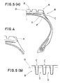
- Figs.5 (a) and (b) provided tyres having shoulder grooves C extending radially inwardly from the tread edge portions A to the shoulder portion B so that the heat accumulating power of the shoulder portion B is diminished and heat radiation therefrom is promoted.
- an object of the present invention to provide a pneumatic tyre, in which an excessive rise in the temperature of the rubber in the shoulder portions and uneven wear of the tread are effectively prevented to extend the tyre life, and which can facilitate the worn tread removing work in a tyre retreading process.
- a pneumatic tyre having a tread region and a pair of shoulder regions extending radially inwardly one from each edge of the tread region characterised in that each shoulder region is provided with shoulder grooves and buttress hollows, said shoulder grooves being arranged circumferentially of the tyre and extending radially inwardly from the tread edges and terminating at a distance L1 radially inwardly from the outer surface of the tread region so that the radially inner ends thereof are located on a circle at the surface of each shoulder region, said buttress hollows being arranged circumferentially of the tyre so as to be positioned one between two circumferentially adjacent shoulder grooves, and the radially outermost ends of said buttress hollows being located radially inwardly of said radially innermost ends of the shoulder grooves.
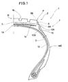
- a pneumatic tyre 1 comprises a radial carcass 13 turned up in both edge portions around a pair of bead cores 12, a tread 15 having edges P disposed radially outside the carcass, and a belt 14 disposed between the carcass and the tread and composed of at least two plies of inextensible cords.
- the tread 15 has a pair of shoulder regions 2 located adjacent to the edges P and extending radially inwardly therefrom, a pair of sidewalls situated radially inward of the shoulder regions 2 and a pair of bead regions.
- the distance L1 between the boundary 5 and the outer surface of the tread 15 is usually 0.5 to 4 % of the overall outer diameter of the tyre when new.
- the tyre 1 is provided in the shoulder region 2 with shoulder grooves 6 and buttress hollows 10, thereby defining a buttressed portion 7 on each side of the tyre.
- the buttressed portion 7 is situated radially outwardly of the tyre maximum width point WE.
- the shoulder grooves 6 are spaced in the circumferential direction at regular intervals. However, to reduce the sound pressure level of the pattern noise, they are more preferably arranged at irregular intervals according to a variable pitching method.
- each shoulder groove 6 opens at the outer surface of the tread, and the radially inner end is located at the above-mentioned boundary 5. That is, the shoulder grooves 6 terminate at a distance L1 which is in the range of 0.5 to 4 % of the overall diameter of the tyre when new from the outer surface of the tread 15.
- the width of the shoulder groove 6 is properly set in accordance with the outer diameter of the tyre and the intervals or the pitches of the shoulder grooves 6.
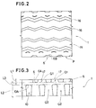
- each shoulder groove 6 is obliquely formed as shown in Fig. 2 and the corners are rounded off to prevent crack propagation from the repeated deformations during tyre rotations.
- the shoulder grooves 6 may be formed in a triangular shape in cross section as shown in Fig.4.
- each buttress hollow 10 is arranged in the circumferential direction of the tyre so that each buttress hollow 10 is located substantially centrally between two adjacent shoulder grooves 6.
- each buttress hollow 10 is positioned at a distance L3 radially inwards of the boundary 5 which is the position of the radially inner ends 6A of the grooves.
- the distance L3 is in the range of 0.2 to 4 % of the outer diameter of the tyre.
- each shoulder region 2 is provided with a circumferentially continuously extending rib whose outer surface is devoid of any grooves or hollows.
- the rigidity of the resultant buttressed part 17 between adjacent shoulder grooves 6 is large enough to cause partial wear or uneven wear around each buttressed part 17. Further, because the total volume of the rubber used in the thick gauge parts such as the L3 width part or rib and the buttresses Q1 and Q2 is increased, the effect of decreasing the heat generation then becomes less and the distribution of the internal temperature becomes uneven, thereby increasing the internal strain in the buttressed portion 7.
- the buttress hollows 10 are so formed that the maximum groove depth D is 5mm or so, and the length L2 exceeds 0.8% of the outer diameter of the tyre.
- the effect of forming the buttress hollows 10 becomes insufficient for diminishing the heat accumulating power of the shoulder portion 2 and promoting the heat radiation therefrom.
- each buttress hollow 10 is so formed that the bottom 10B thereof is smoothly curved up to the surface of its surrounding.
- the pneumatic tyre according to the present invention is provided in each shoulder region with the buttressed portion 7 so constructed that the shoulder grooves 6 and the buttress hollows 10 are formed alternatively on each side of the circumferentially continuously extending rib. Accordingly, the rubber in the shoulder regions has thick parts and thin parts uniformly, that is, on the whole it has a uniform thickness. As a result, the internal heat generation of the tyre and the difference in rigidity of the rubber can be decreased more evenly in comparison with conventional tyres, which ensures an effective prevention of ply separation and rubber separation at the belt edge.
- the buttress parts 17 between the shoulder grooves 6 are provided with less radial support because the buttress hollows 10 are disposed radially inwardly thereof. Accordingly, the rigidity of such parts does not become much higher than that of the surrounding parts, and as a result, uneven wear such as shoulder wear in which the tread edge portions wear rapidly in comparison with the tread crown portion is effectively prevented.
- the shoulder grooves 6 are so arranged in the circumferential direction of the tyre that their inner ends 6A are brought into a line. Accordingly, when the tread 15 has been worn out and the tyre is put to a retreading process, the inner ends 6A provide the worker with a guide line showing the above mentioned boundary 5 at which the worker must remove the worn tread rubber, which facilitates the worn tread removing work and avoids frequent measuring of the tyre dimensions. This ensures effective reduction in working hours and retreading cost together with an accurately worked tyre and a good external appearance for the retreaded tyre.
Landscapes
- Engineering & Computer Science (AREA)
- Mechanical Engineering (AREA)
- Tires In General (AREA)
Claims (4)
- Luftreifen mit einem Laufflächenbereich (15) und einem Paar von sich ausgehend von jeder Ecke (P) des Laufflächenbereiches (15) radial einwärts erstreckenden Schulterbereichen (2),
dadurch gekennzeichnet,
daß jeder Schulterbereich (2) mit Schulteraussparungen (6) und gegenstützenden Aushöhlungen (10) ausgestattet ist, wobei die Schulteraussparungen (6) in Umfangsrichtung des Reifens angeordnet sind und sich radial einwärts der Ränder (P) der Laufflächen erstrecken und in einem Abstand (L1) radial einwärts von der äußeren Oberfläche des Laufflächenbereiches (15) enden, so daß die radial inneren Enden auf einem Kreis an der Oberfläche jedes Schulterbereiches (2) gelegen sind, wobei die gegenstützenden Aushöhlungen (10) so auf dem Umfang des Reifens angeordnet sind, daß jeweils eine Aushöhlung zwischen zwei in Umfangsrichtung benachbarten Schulteraussparungen (6) positioniert ist, und die radial äußersten Enden der gegenstutzenden Aushöhlungen (10) radial innerhalb der radial innersten Enden der Schulteraussparungen (6) angeordnet sind. - Luftreifen nach Anspruch 1,
dadurch gekennzeichnet,
daß der Abstand (L1) der radial innersten Enden der Schulteraussparungen (B) von der äußeren Oberfläche des Laufflächenbereiches (15) im Bereich von 0.5 bis 4 % des Außendurchmessers des Reifens liegt. - Luftreifen nach Anspruch 1 oder 2,
dadurch gekennzeichnet,
daß der Abstand (L3) der radial äußersten Enden (10A) jeder gegenstützenden Aushöhlung (10) von den radial innersten Enden der Schulteraussparungen (6) im Bereich von 0.2 bis 4% des Außendurchmessers des Reifens liegt. - Luftreifen nach Anspruch 1, 2 oder 3,
gekennzeichnet dadurch,
daß die Maximaltiefe und die Länge (L2) der gegenstützenden Aushöhlungen (10) jeweils im wesentlichen 5 mm und mehr als 0.8 % des Außendurchmessers des Reifens beträgt.
Applications Claiming Priority (2)
| Application Number | Priority Date | Filing Date | Title |
|---|---|---|---|
| JP304072/87 | 1987-11-30 | ||
| JP62304072A JPH01145206A (ja) | 1987-11-30 | 1987-11-30 | 空気入りタイヤ |
Publications (3)
| Publication Number | Publication Date |
|---|---|
| EP0320143A2 EP0320143A2 (de) | 1989-06-14 |
| EP0320143A3 EP0320143A3 (en) | 1989-12-13 |
| EP0320143B1 true EP0320143B1 (de) | 1992-05-13 |
Family
ID=17928691
Family Applications (1)
| Application Number | Title | Priority Date | Filing Date |
|---|---|---|---|
| EP88311062A Expired EP0320143B1 (de) | 1987-11-30 | 1988-11-23 | Luftreifen |
Country Status (4)
| Country | Link |
|---|---|
| EP (1) | EP0320143B1 (de) |
| JP (1) | JPH01145206A (de) |
| DE (1) | DE3871098D1 (de) |
| MY (1) | MY103480A (de) |
Families Citing this family (14)
| Publication number | Priority date | Publication date | Assignee | Title |
|---|---|---|---|---|
| JPH0331007A (ja) * | 1989-06-28 | 1991-02-08 | Sumitomo Rubber Ind Ltd | 空気入りタイヤ |
| JPH04238703A (ja) * | 1991-01-10 | 1992-08-26 | Sumitomo Rubber Ind Ltd | 空気入りタイヤ |
| JP2955202B2 (ja) * | 1995-02-13 | 1999-10-04 | 住友ゴム工業株式会社 | 空気入りタイヤ |
| US6955782B1 (en) | 1999-11-24 | 2005-10-18 | The Goodyear Tire & Rubber Company | Method of molding a tire and mold therefor |
| CA2391154A1 (en) * | 1999-11-24 | 2001-05-31 | The Goodyear Tire & Rubber Company | A method of molding a tire and mold therefore |
| US6564839B1 (en) * | 2000-11-01 | 2003-05-20 | The Goodyear Tire & Rubber Company | Pneumatic tire having a load dependent adaptive footprint shape |
| US7341082B2 (en) * | 2004-12-28 | 2008-03-11 | The Goodyear Tire & Rubber Company | Shoulder ribs for pneumatic tires |
| JP4886812B2 (ja) | 2009-05-18 | 2012-02-29 | 東洋ゴム工業株式会社 | 空気入りタイヤ |
| JP5667410B2 (ja) * | 2010-10-19 | 2015-02-12 | 住友ゴム工業株式会社 | 空気入りラジアルタイヤ |
| JP5830861B2 (ja) * | 2011-01-07 | 2015-12-09 | 横浜ゴム株式会社 | タイヤ更生方法及びタイヤ更生用バフ装置 |
| WO2014057548A1 (ja) * | 2012-10-10 | 2014-04-17 | 横浜ゴム株式会社 | 空気入りタイヤ |
| JP6056360B2 (ja) * | 2012-10-11 | 2017-01-11 | 横浜ゴム株式会社 | 更生タイヤ |
| JP6959850B2 (ja) * | 2017-12-12 | 2021-11-05 | 株式会社ブリヂストン | 重荷重用タイヤ |
| JP2019104361A (ja) * | 2017-12-12 | 2019-06-27 | 株式会社ブリヂストン | 重荷重用タイヤ |
Family Cites Families (5)
| Publication number | Priority date | Publication date | Assignee | Title |
|---|---|---|---|---|
| FR863821A (fr) * | 1940-03-04 | 1941-04-10 | Seiberling Rubber Co | Perfectionnements aux enveloppes pneumatiques |
| GB746479A (en) * | 1953-02-03 | 1956-03-14 | Dunlop Rubber Co | Improvements in pneumatic tyres |
| JPS5490702A (en) * | 1977-12-28 | 1979-07-18 | Bridgestone Corp | Tire with lug |
| USRE30549E (en) * | 1978-10-23 | 1981-03-24 | Uniroyal, Inc. | Pneumatic tire |
| DE3132310A1 (de) * | 1981-08-17 | 1983-03-03 | Bayer Ag, 5090 Leverkusen | Luftreifen fuer schwere belastung |
-
1987
- 1987-11-30 JP JP62304072A patent/JPH01145206A/ja active Granted
-
1988
- 1988-11-18 MY MYPI88001312A patent/MY103480A/en unknown
- 1988-11-23 DE DE8888311062T patent/DE3871098D1/de not_active Expired - Fee Related
- 1988-11-23 EP EP88311062A patent/EP0320143B1/de not_active Expired
Also Published As
| Publication number | Publication date |
|---|---|
| MY103480A (en) | 1993-06-30 |
| EP0320143A3 (en) | 1989-12-13 |
| DE3871098D1 (de) | 1992-06-17 |
| JPH0581442B2 (de) | 1993-11-12 |
| EP0320143A2 (de) | 1989-06-14 |
| JPH01145206A (ja) | 1989-06-07 |
Similar Documents
| Publication | Publication Date | Title |
|---|---|---|
| EP0320143B1 (de) | Luftreifen | |
| EP0726174B1 (de) | Luftreifen und Verfahren zu seiner Herstellung | |
| EP0246995B1 (de) | Lauffläche von Luftreifen | |
| JP4209319B2 (ja) | オフザロードタイヤ | |
| EP0492048B1 (de) | Gewölbte Ersatzlauffläche | |
| JP5322610B2 (ja) | 空気入りタイヤ及び空気入りタイヤの製造方法 | |
| EP2022615B1 (de) | Formwerkzeug zur Vulkanisierung eines Reifens und Mittels des Formwerkzeuges vulkanisierter Luftreifen | |
| US4305446A (en) | Cast tire and method of manufacture | |
| EP0413574A2 (de) | Radialer Luftreifen für grosse Geschwindigkeit | |
| JPH0680004A (ja) | 空気入りタイヤ | |
| US3198234A (en) | Method of repairing pneumatic tires and patches therefor | |
| EP1400375B1 (de) | LKW Lenkreifen, Reifenformwerkzeug und Verfahren zum Formen | |
| JPH11151909A (ja) | 重荷重用空気入りタイヤ | |
| JP4017218B2 (ja) | 航空機用空気入りタイヤ | |
| CA1313116C (en) | Pneumatic radial tire for heavy-duty vehicles | |
| EP0333397B1 (de) | Radialer Luftreifen | |
| JPH05185808A (ja) | 建設車両用ラジアルタイヤ | |
| JP3210421B2 (ja) | 空気入りラジアルタイヤの製造方法 | |
| JPH0338407A (ja) | プレキュアトレッド | |
| JP4333822B2 (ja) | 大型車両用タイヤ | |
| JPH1148714A (ja) | 空気入りタイヤ | |
| JPH02133202A (ja) | 重荷重用空気入りタイヤ | |
| JP2002240511A (ja) | 重荷重用ラジアルタイヤ | |
| JPH10217717A (ja) | 重荷重用空気入りラジアルタイヤ | |
| JPS6220703A (ja) | モ−タ−サイクル用空気入りタイヤ |
Legal Events
| Date | Code | Title | Description |
|---|---|---|---|
| PUAI | Public reference made under article 153(3) epc to a published international application that has entered the european phase |
Free format text: ORIGINAL CODE: 0009012 |
|
| AK | Designated contracting states |
Kind code of ref document: A2 Designated state(s): DE FR GB |
|
| PUAL | Search report despatched |
Free format text: ORIGINAL CODE: 0009013 |
|
| AK | Designated contracting states |
Kind code of ref document: A3 Designated state(s): DE FR GB |
|
| 17P | Request for examination filed |
Effective date: 19900403 |
|
| 17Q | First examination report despatched |
Effective date: 19910925 |
|
| GRAA | (expected) grant |
Free format text: ORIGINAL CODE: 0009210 |
|
| AK | Designated contracting states |
Kind code of ref document: B1 Designated state(s): DE FR GB |
|
| REF | Corresponds to: |
Ref document number: 3871098 Country of ref document: DE Date of ref document: 19920617 |
|
| ET | Fr: translation filed | ||
| PLBE | No opposition filed within time limit |
Free format text: ORIGINAL CODE: 0009261 |
|
| STAA | Information on the status of an ep patent application or granted ep patent |
Free format text: STATUS: NO OPPOSITION FILED WITHIN TIME LIMIT |
|
| 26N | No opposition filed | ||
| PGFP | Annual fee paid to national office [announced via postgrant information from national office to epo] |
Ref country code: FR Payment date: 20011113 Year of fee payment: 14 |
|
| PGFP | Annual fee paid to national office [announced via postgrant information from national office to epo] |
Ref country code: GB Payment date: 20011121 Year of fee payment: 14 |
|
| PGFP | Annual fee paid to national office [announced via postgrant information from national office to epo] |
Ref country code: DE Payment date: 20011210 Year of fee payment: 14 |
|
| REG | Reference to a national code |
Ref country code: GB Ref legal event code: IF02 |
|
| PG25 | Lapsed in a contracting state [announced via postgrant information from national office to epo] |
Ref country code: GB Free format text: LAPSE BECAUSE OF NON-PAYMENT OF DUE FEES Effective date: 20021123 |
|
| PG25 | Lapsed in a contracting state [announced via postgrant information from national office to epo] |
Ref country code: DE Free format text: LAPSE BECAUSE OF NON-PAYMENT OF DUE FEES Effective date: 20030603 |
|
| GBPC | Gb: european patent ceased through non-payment of renewal fee | ||
| PG25 | Lapsed in a contracting state [announced via postgrant information from national office to epo] |
Ref country code: FR Free format text: LAPSE BECAUSE OF NON-PAYMENT OF DUE FEES Effective date: 20030731 |
|
| REG | Reference to a national code |
Ref country code: FR Ref legal event code: ST |