EP0319208A1 - Procédé d'hydrogénation - Google Patents
Procédé d'hydrogénation Download PDFInfo
- Publication number
- EP0319208A1 EP0319208A1 EP88311188A EP88311188A EP0319208A1 EP 0319208 A1 EP0319208 A1 EP 0319208A1 EP 88311188 A EP88311188 A EP 88311188A EP 88311188 A EP88311188 A EP 88311188A EP 0319208 A1 EP0319208 A1 EP 0319208A1
- Authority
- EP
- European Patent Office
- Prior art keywords
- hydrogenation
- bed
- hydrogen
- catalyst
- liquid
- Prior art date
- Legal status (The legal status is an assumption and is not a legal conclusion. Google has not performed a legal analysis and makes no representation as to the accuracy of the status listed.)
- Granted
Links
Images


Classifications
-
- B—PERFORMING OPERATIONS; TRANSPORTING
- B01—PHYSICAL OR CHEMICAL PROCESSES OR APPARATUS IN GENERAL
- B01J—CHEMICAL OR PHYSICAL PROCESSES, e.g. CATALYSIS OR COLLOID CHEMISTRY; THEIR RELEVANT APPARATUS
- B01J8/00—Chemical or physical processes in general, conducted in the presence of fluids and solid particles; Apparatus for such processes
- B01J8/02—Chemical or physical processes in general, conducted in the presence of fluids and solid particles; Apparatus for such processes with stationary particles, e.g. in fixed beds
-
- C—CHEMISTRY; METALLURGY
- C07—ORGANIC CHEMISTRY
- C07C—ACYCLIC OR CARBOCYCLIC COMPOUNDS
- C07C31/00—Saturated compounds having hydroxy or O-metal groups bound to acyclic carbon atoms
- C07C31/02—Monohydroxylic acyclic alcohols
- C07C31/125—Monohydroxylic acyclic alcohols containing five to twenty-two carbon atoms
-
- C—CHEMISTRY; METALLURGY
- C07—ORGANIC CHEMISTRY
- C07B—GENERAL METHODS OF ORGANIC CHEMISTRY; APPARATUS THEREFOR
- C07B31/00—Reduction in general
-
- C—CHEMISTRY; METALLURGY
- C07—ORGANIC CHEMISTRY
- C07C—ACYCLIC OR CARBOCYCLIC COMPOUNDS
- C07C29/00—Preparation of compounds having hydroxy or O-metal groups bound to a carbon atom not belonging to a six-membered aromatic ring
- C07C29/132—Preparation of compounds having hydroxy or O-metal groups bound to a carbon atom not belonging to a six-membered aromatic ring by reduction of an oxygen containing functional group
- C07C29/136—Preparation of compounds having hydroxy or O-metal groups bound to a carbon atom not belonging to a six-membered aromatic ring by reduction of an oxygen containing functional group of >C=O containing groups, e.g. —COOH
- C07C29/14—Preparation of compounds having hydroxy or O-metal groups bound to a carbon atom not belonging to a six-membered aromatic ring by reduction of an oxygen containing functional group of >C=O containing groups, e.g. —COOH of a —CHO group
- C07C29/141—Preparation of compounds having hydroxy or O-metal groups bound to a carbon atom not belonging to a six-membered aromatic ring by reduction of an oxygen containing functional group of >C=O containing groups, e.g. —COOH of a —CHO group with hydrogen or hydrogen-containing gases
-
- B—PERFORMING OPERATIONS; TRANSPORTING
- B01—PHYSICAL OR CHEMICAL PROCESSES OR APPARATUS IN GENERAL
- B01J—CHEMICAL OR PHYSICAL PROCESSES, e.g. CATALYSIS OR COLLOID CHEMISTRY; THEIR RELEVANT APPARATUS
- B01J2208/00—Processes carried out in the presence of solid particles; Reactors therefor
- B01J2208/00008—Controlling the process
- B01J2208/00017—Controlling the temperature
- B01J2208/00026—Controlling or regulating the heat exchange system
- B01J2208/00035—Controlling or regulating the heat exchange system involving measured parameters
- B01J2208/00044—Temperature measurement
- B01J2208/00061—Temperature measurement of the reactants
-
- B—PERFORMING OPERATIONS; TRANSPORTING
- B01—PHYSICAL OR CHEMICAL PROCESSES OR APPARATUS IN GENERAL
- B01J—CHEMICAL OR PHYSICAL PROCESSES, e.g. CATALYSIS OR COLLOID CHEMISTRY; THEIR RELEVANT APPARATUS
- B01J2208/00—Processes carried out in the presence of solid particles; Reactors therefor
- B01J2208/00008—Controlling the process
- B01J2208/00017—Controlling the temperature
- B01J2208/00106—Controlling the temperature by indirect heat exchange
- B01J2208/00115—Controlling the temperature by indirect heat exchange with heat exchange elements inside the bed of solid particles
- B01J2208/00141—Coils
-
- B—PERFORMING OPERATIONS; TRANSPORTING
- B01—PHYSICAL OR CHEMICAL PROCESSES OR APPARATUS IN GENERAL
- B01J—CHEMICAL OR PHYSICAL PROCESSES, e.g. CATALYSIS OR COLLOID CHEMISTRY; THEIR RELEVANT APPARATUS
- B01J2208/00—Processes carried out in the presence of solid particles; Reactors therefor
- B01J2208/00008—Controlling the process
- B01J2208/00017—Controlling the temperature
- B01J2208/00106—Controlling the temperature by indirect heat exchange
- B01J2208/00168—Controlling the temperature by indirect heat exchange with heat exchange elements outside the bed of solid particles
- B01J2208/00212—Plates; Jackets; Cylinders
-
- B—PERFORMING OPERATIONS; TRANSPORTING
- B01—PHYSICAL OR CHEMICAL PROCESSES OR APPARATUS IN GENERAL
- B01J—CHEMICAL OR PHYSICAL PROCESSES, e.g. CATALYSIS OR COLLOID CHEMISTRY; THEIR RELEVANT APPARATUS
- B01J2208/00—Processes carried out in the presence of solid particles; Reactors therefor
- B01J2208/00008—Controlling the process
- B01J2208/00017—Controlling the temperature
- B01J2208/00106—Controlling the temperature by indirect heat exchange
- B01J2208/00168—Controlling the temperature by indirect heat exchange with heat exchange elements outside the bed of solid particles
- B01J2208/00256—Controlling the temperature by indirect heat exchange with heat exchange elements outside the bed of solid particles in a heat exchanger for the heat exchange medium separate from the reactor
-
- B—PERFORMING OPERATIONS; TRANSPORTING
- B01—PHYSICAL OR CHEMICAL PROCESSES OR APPARATUS IN GENERAL
- B01J—CHEMICAL OR PHYSICAL PROCESSES, e.g. CATALYSIS OR COLLOID CHEMISTRY; THEIR RELEVANT APPARATUS
- B01J2208/00—Processes carried out in the presence of solid particles; Reactors therefor
- B01J2208/00008—Controlling the process
- B01J2208/00017—Controlling the temperature
- B01J2208/00477—Controlling the temperature by thermal insulation means
- B01J2208/00495—Controlling the temperature by thermal insulation means using insulating materials or refractories
-
- B—PERFORMING OPERATIONS; TRANSPORTING
- B01—PHYSICAL OR CHEMICAL PROCESSES OR APPARATUS IN GENERAL
- B01J—CHEMICAL OR PHYSICAL PROCESSES, e.g. CATALYSIS OR COLLOID CHEMISTRY; THEIR RELEVANT APPARATUS
- B01J2208/00—Processes carried out in the presence of solid particles; Reactors therefor
- B01J2208/00008—Controlling the process
- B01J2208/00017—Controlling the temperature
- B01J2208/0053—Controlling multiple zones along the direction of flow, e.g. pre-heating and after-cooling
-
- B—PERFORMING OPERATIONS; TRANSPORTING
- B01—PHYSICAL OR CHEMICAL PROCESSES OR APPARATUS IN GENERAL
- B01J—CHEMICAL OR PHYSICAL PROCESSES, e.g. CATALYSIS OR COLLOID CHEMISTRY; THEIR RELEVANT APPARATUS
- B01J2208/00—Processes carried out in the presence of solid particles; Reactors therefor
- B01J2208/00008—Controlling the process
- B01J2208/00539—Pressure
-
- B—PERFORMING OPERATIONS; TRANSPORTING
- B01—PHYSICAL OR CHEMICAL PROCESSES OR APPARATUS IN GENERAL
- B01J—CHEMICAL OR PHYSICAL PROCESSES, e.g. CATALYSIS OR COLLOID CHEMISTRY; THEIR RELEVANT APPARATUS
- B01J2208/00—Processes carried out in the presence of solid particles; Reactors therefor
- B01J2208/00008—Controlling the process
- B01J2208/00548—Flow
-
- B—PERFORMING OPERATIONS; TRANSPORTING
- B01—PHYSICAL OR CHEMICAL PROCESSES OR APPARATUS IN GENERAL
- B01J—CHEMICAL OR PHYSICAL PROCESSES, e.g. CATALYSIS OR COLLOID CHEMISTRY; THEIR RELEVANT APPARATUS
- B01J2208/00—Processes carried out in the presence of solid particles; Reactors therefor
- B01J2208/00008—Controlling the process
- B01J2208/0061—Controlling the level
Definitions
- This invention relates to a liquid phase catalytic hydrogenation process.
- Heterogeneous catalytic hydrogenation processes of various kinds are widely practised on a commercial scale and are used for hydrogenation of a wide variety of organic feedstocks.
- Such hydrogenation reactions are conducted at a pressure of from about 1 bar to about 300 bar and at a temperature in the range of from about 40°C to about 380°C.
- Examples include hydrogenation of aldehydes to alcohols, of unsaturated hydrocarbons to saturated hydrocarbons, of acetylene-derived chemicals to saturated materials, of unsaturated fatty acids to saturated fatty acids, of ketones to secondary alcohols, of esters of unsaturated fatty acids to esters of partially or fully hydrogenated fatty acids, of nitriles to primary amines, and of certain sugars to polyhydroxyalcohols.
- quinones for example the hydrogenation of 2-ethylanthraquinone as a step in the production of hydrogen peroxide.
- This cyclohexanol is produced commercially by catalytic hydrogenation of cyclohexanone, and iso -propanol by catalytic hydrogenation of acetone.
- An example of hydrogenation of an unsaturated hydrocarbon is the production of cyclohexane from benzene.
- Typical catalysts for such hydrogenation reactions include Group VIII metal catalysts, such as nickel, palladium and platinum.
- butane-1,4-diol by hydrogenation of but-2-yn-1,4-diol is an example of hydrogenation of an acetylene-derived chemical.
- a suitable catalyst for this reaction has been described as a granular nickel-copper-manganese on silica gel.
- the production of stearic acid by catalytic hydrogenation of the corresponding unsaturated acids, linoleic acid and linolenic acid, at a temperature of about 150°C and at a pressure of about 14.75 bar to about 32 bar and using a nickel, cobalt, platinum, palladium, chromium or copper/zinc catalyst, is an example of the hydrogenation of unsaturated fatty acids to yield saturated fatty acids.
- So-called "hardening" of vegetable oils is an example of hydrogenation of esters of unsaturated fatty acids.
- Production of beta -phenylethylamine by hydrogenation of benzyl cyanide is an example of hydrogenation of a nitrile.
- hydrogenation of sugars to polyhydroxyalcohols there can be mentioned hydrogenation of ketose and aldose sugars to hexahydroxyalcohols, for example hydrogenation of D-glucose to sorbitol and of D-mannose to mannitol.
- alkanols An important route to C3 and higher alkanols involves hydroformylation of alpha -olefins, such as ethylene, propylene, and butene-1, to yield the corresponding aldehyde having one more carbon atom than the starting olefin.
- alpha -olefins such as ethylene, propylene, and butene-1
- ethylene yields propionaldehyde
- propylene yields a mixture of n - and iso -butyraldehyde (with the n -isomer usually predominating).
- These aldehydes yield the corresponding alkanols, e.g. n -propanol and n -butanol, upon catalytic hydrogenation.
- the important plasticiser alcohol, 2-ethylhexanol is made by alkali-catalysed condensation of n -butyraldehyde to yield the unsaturated aldehyde, 2-ethyl-hex-2-enal, which is then hydrogenated to yield the desired 2-ethylhexanol.
- the preferred catalysts for such aldehyde hydrogenation reactions used to be Group VIII metal catalysts, such as nickel, palladium or platinum the use of a solid catalyst comprising a reduced mixture of CuO and ZnO under vapour phase conditions has also been proposed (see EP-A-0008767 and US-A-2549416).
- Molybdenum sulphide supported on an activated carbon carrier has also been suggested in GB-A-765972.
- the hydrogenation of an aldehyde feed containing ring-type sulphur compounds using a reduced mixture of oxides or hydroxides of copper and zinc is described in US-A-4052467. Copper chromite has also been used as an aldehyde hydrogenation catalyst.
- Hydrodesulphurisation is another commercially important hydrogenation reaction. This is the removal complex organic sulphur compounds, such as sulphides, disulphides, benzothiophene and the like, from a mixed hydrocarbon feedstock by catalytic reaction with hydrogen to form hydrogen sulphide.
- organic sulphur compounds such as sulphides, disulphides, benzothiophene and the like
- typical operating conditions include use of a temperature of from about 260°C to about 375°C, a hydrogen pressure of from about 5 bar to about 40 bar and an alumina supported cobalt-molybdenum or nickel-molybdenum catalyst.
- Catalytic hydrogenation is in all the above cases a heterogeneous process. It may be operated as a liquid phase process or as a vapour phase process.
- a review of some of the factors involved in designing heterogeneous gas and vapour phase reaction systems appeared in "Chemical Engineering", July 1955, in an article entitled “Moving Bed Processes ... New Applications”, at pages 198 to 206 (see - in particular pages 204 and 205 thereof).
- DE-B-1115232 describes a process for the production of alcohols with 2 to 6 carbon atoms by hydrogenation in the liquid phase over a nickel or cobalt catalyst of a feed mixture comprising the corresponding aldehyde diluted with from 50 to 300 volume % of product alcohol, using two hydrogenation stages connected in series.
- Reaction conditions include use of a temperature of 130°C to 220°C and a pressure of less than 50 bar, whilst the aldehyde feed rate corresponds to a space velocity of from 0.3 to 2.5 hr ⁇ 1, preferably 0.75 to 1.1 hr ⁇ 1.
- An excess of hydrogen is recirculated from the exit end of the second hydrogenation stage to the inlet end of the first hydrogenation stage.
- GB-A-784359 is concerned with preferential hydrogenation of aldehydes in a mixture of aldehydes and olefins, water being added to inhibit olefin hydrogenation. Multi-bed co-current hydrogenation is used, with injection of hydrogen between beds. Hydrogen recycle is envisaged.
- GB-A-1175709 describes an apparatus for production of cyclohexane by catalytic hydrogenation of benzene. Excess hydrogen is recycled.
- CA-A-926847 discloses in Example 2 a process in which a solution of 2-ethylanthraquinone is passed through a tubular reactor in co-current with hydrogen.
- US-A-3009782 describes a similar process in which the working solution is passed through a fixed bed of the hydrogenation catalyst at a rate of between 20 and 200 litres per minute per square foot of catalyst bed cross-section (215.3 and 2152.8 litres per minute per square metre of catalyst bed).
- trickle bed reactor is often used to describe a reactor in which a liquid phase and a gas phase flow concurrently downward through a fixed bed of catalyst particles while reaction takes place.
- the liquid trickles over the packing in essentially a laminar film or in rivulets, and the gas flows continuously through the voids in the bed.
- This is sometimes termed the gas continuous region or homogeneous flow and is the type encountered usually in laboratory and pilot scale operations.
- gas and/or liquid flow rates are increased there is encountered behaviour described as rippling, slugging or pulsing flow. Such behaviour may be characteristic of the higher operating rates encountered in commercial petroleum processing.
- the present invention seeks to provide an improved liquid phase hydrogenation process in which essentially 100% hydrogenation of the aldehyde or other organic feedstock to the desired hydrogenation product can be achieved, with minimisation of formation of by-products.
- a liquid phase catalytic hydrogenation process in which an organic feedstock is contacted with hydrogen in the presence of a solid hydrogenation catalyst under hydrogenation conditions to produce a hydrogenation product, which process comprises passing a feed solution of the organic feedstock in an inert diluent therefor downwardly in co-current with a hydrogen-containing gas through a hydrogenation zone containing a bed of a particulate hydrogenation catalyst whose particles substantially all lie in the range of from about 0.5 mm to about 5 mm, maintaining the bed of catalyst particles under temperature and pressure conditions conducive to hydrogenation, recovering from a bottom part of the bed a liquid phase containing the hydrogenation product, controlling the rate of supply of the feed solution to the bed so as to maintain a superficial liquid velocity of the liquid down the bed in the range of from about 1.5 cm/sec to about 5 cm/sec, and controlling the rate of supply of the hydrogen-containing gas to the bed so as to maintain at the top surface of the bed of catalyst particles a flow of hydrogen-containing gas containing from 1.00 to
- the catalyst particle size range is from about 0.5 mm to about 3 mm.
- the process of the invention is not specific to any particular hydrogenation reaction or to any particular catalyst composition.
- the hydrogenation conditions used in the hydrogenation zone include use of a pressure of from about 1 bar to about 300 bar, often from about 1 bar to about 100 bar, and of a temperature of from about 40°C to about 350°C, often from about 90°C to about 220°C.
- a pressure drop is set up across the catalyst bed, typically of at least about 0.1 kg/cm2 per metre of catalyst bed depth. Care must accordingly be taken, in designing a plant to operate according to the invention, that it is ensured that at the bottom of the catalyst bed the crushing strength of the catalyst is not equalled or exceeded. If there is any risk of this occurring, then it is necessary to utilise two or more catalyst beds of appropriate depth in place of a single large catalyst bed; in this case gas and liquid must be uniformly distributed into each bed.
- the selection of catalyst particle size and of the superficial liquid velocity are features which are crucial to the process of the invention. These features ensure that the catalyst surface is completely wetted, that a large catalyst superficial surface area is presented for reaction of the unsaturated organic compound or other organic feedstock with hydrogen, that good liquid-gas contact is effected as the gas bubbles entrained in the liquid pass through the irregular channels in the bed in co-current downflow through the bed, that dissolution of hydrogen into the downflowing liquid is thereby facilitated, and that good mass transfer of the dissolved hydrogen and unsaturated organic compound or other organic feedstock to the catalyst surface is also achieved by the relatively rapid flow of the liquid through the complex network of interconnecting passages present in the catalyst bed.
- the actual velocity of the liquid over the catalyst surface can be up to about 3 times the superficial velocity of the gas plus liquid.
- concentration of the unsaturated organic compound or other organic feedstock in the liquid phase is another important factor.
- concentration of unsaturated organic compound or other organic feedstock in the liquid phase helps to limit the temperature rise, particularly when the hydrogenation zone is operated under adiabatic conditions.
- Such "blinding" of the catalyst will occur, it is postulated, if one or more of the species present, whether the unsaturated organic compound or other organic feedstock or some hydrogenation product thereof, is strongly absorbed or adsorbed on the catalyst surface and thereby prevents approach of hydrogen molecules to the active catalytic sites.
- the process of the invention can be applied, for example to the hydrogenation of unsaturated hydrocarbons to saturated hydrocarbons. Typical of such a reaction is the production of cyclohexane from benzene.
- This hydrogenation can be carried out according to the invention using a nickel, palladium or platinum catalyst in the hydrogenation zone and a temperature of from about 100°C to about 200°C and a pressure of from about 5 bar to about 30 bar. This reaction is exothermic.
- Production of secondary alcohols by reduction of ketones is another appropriate hydrogenation reaction to which the invention can be applied.
- Examples of such reactions include production of iso -propanol from acetone and of cyclohexanol from cyclohexanone.
- a hydrogenation reaction to which the present invention can be applied is the production of butane-1,4-diol by hydrogenation of but-2-yn-1,4-diol.
- This can be carried out using a catalyst which is a granular nickel-copper-manganese on silica gel at a pressure of from about 200 bar to about 300 bar in the hydrogenation zone.
- a typical inlet temperature to the hydrogenation zone is about 40°C, when the catalyst is freshly reduced.
- a further example of a hydrogenation reaction to which the process of the invention can be applied is the production of stearic acid by hydrogenation of linoleic acid, of linolenic acid, or of a mixture thereof.
- This can be carried out using a nickel, cobalt, platinum, palladium, chromium or zinc catalyst at a pressure of from about 10 bar to about 40 bar and an inlet temperature to the hydrogenation zone of about 150°C.
- hydrogenation processes to which the invention can be applied include "hardening" of vegetable oils, hydrodesulphurization, hydrogenation of nitriles to amines, and hydrogenation of sugars, (for example, hydrogenation of aldoses, such as D-glucose or D-mannose, to the corresponding hexahydroxyalcohols, such as sorbitol and mannitol).
- a particularly preferred type of hydrogenation reaction is the production of alcohols from aldehydes.
- aldehydes generally contain from 2 to about 20 carbon atoms and may in the case of those aldehydes containing 3 or more carbon atoms include one or more unsaturated carbon-carbon bonds besides the unsaturated -CHO group.
- Typical aldehydes include n - and iso -butyraldehydes, n-pentanal, 2-methylbutanal, 2-ethylhex-2-enal, 2-ethylhexanal, 4- t -butoxybutyraldehyde, C10-"OXO"-aldehydes (e.g. 2-propylhept-2-enal), undecanal, dodecanal, tridecanal, crotonaldehyde and furfural, as well as mixtures of two or more thereof.
- n- and iso -butyraldehydes n-pentanal
- 2-methylbutanal 2-ethylhex-2-enal
- 2-ethylhexanal 2-ethylhexanal
- 4- t -butoxybutyraldehyde C10-"OXO"-aldehydes (e.g. 2-propylhept-2
- R.CH CH2 + H2 + CO -- ⁇ R.CH2.CH2.CHO + R.CH(CHO).CH3; where R is a hydrogen atom or an alkyl radical.
- the ratio of the n -aldehyde to the iso -aldehyde in the product depends to a certain extent on the selected hydroformylation conditions and upon the nature of the hydroformylation catalyst used.
- aldehydes can be obtained by condensation reactions; for example, 2-ethylhex-2-enal can be made by condensation of 2 moles of n -butyraldehyde and 2-propylhept-2-enal by condensation of 2 moles of n -valeraldehyde.
- aldehyde hydrogenation reactions are the production of n -butanol from n -butyraldehyde, of 2-ethylhexanol from 2-ethylhex-2-enal, or 2-propylheptanol from 2-propylhept-2-enal, of undecanol from undecanal, and of 4- t -butoxybutanol from 4- t -butoxybutyraldehyde.
- the invention is used to special advantage for hydrogenation of aldehydes containing from about 7 to about 17 carbon atoms to the corresponding alkanols.
- any of the conventionally used supported metal catalysts such as Ni, Pd or Pt supported on a variety of supports such as granular carbon, silica, silica-alumina, zirconia, silicon carbide or the like, or copper chromite.
- aldehyde hydrogenation catalysts include cobalt compounds; nickel compounds which may contain small amounts of chromium or another promoter; mixtures of copper and nickel and/or chromium; and other Group VIII metal catalysts, such as Pt, Pd, Rh and mixtures thereof, on supports, such as carbon, silica, alumina and silica-alumina.
- the nickel compounds are generally deposited on support materials such as alumina or kieselguhr.
- the catalyst particles substantially all have a particle size in the range of from about 0.5 mm to about 5 mm, preferably in the range of from about 0.5 mm to about 3 mm, as measured by a conventional sieve analysis technique.
- substantially all we mean that not more than about 5%, and preferably not more than about 0.5%, of particles are less than about 0.5 mm in size, and that not more than about 5%, and preferably not more than about 1%, of particles are larger than 5 mm (or 3 mm) in size.
- the catalyst particles may be of any desired shape, such as cylindrical, but are conveniently approximately spherical granules. However the use of pelleted catalysts and of catalyst particles of more complex shape is not ruled out.
- the particle size is essentially equivalent to particle diameter, whereas in the case of cylindrical catalyst particles or particles of more complex shape the size range refers to the shortest particle dimension, e.g. diameter in the case of a cylinder or extrudate.
- Particularly preferred catalysts are those with a particle size range of from about 1 mm to about 2 mm.
- the hydrogenation zone may include two or more beds of catalyst. Conveniently, however, the hydrogenation zone comprises a single catalyst bed.
- the depth of the catalyst bed or beds should be sufficient to ensure that the desired degree of conversion (e.g. about 75% to about 99% or higher, for example about 99.5% or more) can be effected in passage through the bed under the selected reaction conditions.
- the hydrogen-containing gas supplied to the hydrogenation zone preferably contains a major amount of hydrogen and at most a minor amount of one or more inert gases, such as nitrogen, methane, other low molecular weight hydrocarbons, such as ethane, propane, n -butane and iso -butane, carbon oxides, neon, argon or the like.
- Preferred hydrogen-containing gases are accordingly gases containing at least about 50 mole % up to about 95 mole % or more (e.g. about 99 mole %), of H2 with the balance comprising one or more of N2, CO, CO2, Ar, Ne, CH4 and other low molecular weight saturated hydrocarbons.
- the presence of CO and CO2 cannot be tolerated and the total carbon oxides concentration should not, in this case, be more than about 5 to 10 ppm by volume.
- Such hydrogen-containing gases can be obtained in conventional manner from synthesis gas and other usual sources of hydrogen-containing gases, followed, if necessary, by appropriate pretreatment to remove impurities, such as sulphurous impurities (e.g. H2S, COS, CH3SH, CH3SCH3, and CH3SSCH3) and halogen-containing impurities (e.g. HCl and CH3Cl) which would exert a deleterious influence on catalytic activity, i.e. catalyst inhibition, poisoning or deactivation, as well as by the removal of the carbon oxides.
- impurities such as sulphurous impurities (e.g. H2S, COS, CH3SH, CH3SCH3, and CH3SSCH3) and halogen-containing impurities (e.g. HCl and CH3Cl) which would exert a deleterious
- the hydrogen-containing gas supplied to the hydrogenation zone may be, for example, a 94 mole % hydrogen stream produced by steam reforming of natural gas followed by the water gas shift reaction: CO + H2O ⁇ CO2 + H2, then by CO2 removal to give a gas containing about 1 mole % to about 2 mole % carbon oxides, and finally by methanation to give a gas containing only a few ppm by volume of carbon oxides.
- Substantially pure hydrogen from an electrolysis plant may be used, as can also purified hydrogen streams obtained by the pressure swing adsorption treatment of hydrogen admixed with CO, CO2 and light hydrocarbon gases, in each case with excellent results.
- purified hydrogen streams obtained by the pressure swing adsorption treatment of hydrogen admixed with CO, CO2 and light hydrocarbon gases in each case with excellent results.
- pressure swing adsorption reference may be made to a paper entitled "Hydrogen Purification by Pressure Swing Adsorption" by H.A. Stewart and J.L. Heck, prepared for Symposium on Adsorption - Part III, 64th National Meeting of the American Institute of Chemical Engineers, New Orleans, Louisiana, U.S.A., March 16-20, 1969.
- the rate of supply of the feed solution to the catalyst bed corresponds to a superficial liquid velocity down the bed of from about 1.5 cm/sec to about 5 cm/sec, for example from about 1.5 cm/sec to about 3 cm/sec.
- the feed solution supplied to the hydrogenation zone contains the unsaturated organic compound or other organic feedstock dissolved in a compatible diluent therefor.
- the purpose of the diluent is to act as a heat sink, to limit the temperature rise within the hydrogenation zone to an acceptable limit, and also to provide at the same time an appropriate volumetric flow into the catalyst bed, such that the required liquid superficial velocity is achieved along with the desired product conversion and temperature rise.
- the concentration of organic feedstock in the feed solution is accordingly preferably selected in dependence on the expected acceptable temperature rise across the hydrogenation zone; such temperature rise should not be so great as to cause more than a minor amount of vaporisation of liquid in the hydrogenation zone or to cause thermal damage to the catalyst, to any reactant present or to the hydrogenation product.
- the feed solution supplied to the hydrogenation zone contains at least about 1 mole % of an unsaturated organic compound up to about 50 mole %, more preferably in the range of from about 5 mole % up to about 33 mole %, the balance being diluent or diluents.
- the organic feedstock comprises one or more organic sulphurous compounds present in a hydrocarbon diluent.
- concentration of such sulphurous compounds may range from a few ppm, e.g. about 5 ppm up to about 10% by weight.
- the diluent can be any convenient inert liquid or mixture of liquids that is compatible with the unsaturated organic compound or other organic feedstock and the catalyst, with any intermediate product or by-product, and with the desired hydrogenation product.
- the hydrogenation product itself can be used as the compatible diluent or as a part of the compatible diluent.
- the diluent when hydrogenating an aldehyde for example, can be the product alcohol obtained upon hydrogenation of the aldehyde.
- the process of the invention includes the further step of recycling a part of the liquid hydrogenation product for admixture with make up unsaturated organic compound or other organic feedstock to form the feed solution to the hydrogenation zone.
- aldehyde condensation product such as the dimers, trimers and high condensation products of the type disclosed in GB-A-1338237, can be used as diluent.
- unsaturated organic compound or other organic feedstock used as starting material is a solid or if the hydrogenation product or an intermediate product is a solid, then an inert solvent will usually be used.
- use of a solvent may be desirable in cases in which by-product formation is a problem.
- hydrazobenzene is a potential by-product of the hydrogenation of nitrobenzene to yield aniline; in such a case it is desirable to dissolve the unsaturated organic compound, such as nitrobenzene, in a solvent, such as ethanol, in order to limit formation of an undesirable by-product, such as hydrazobenzene.
- a solvent such as ethanol
- ammonia it is also highly advantageous to include a minor amount of ammonia in the ethanol solvent as ammonia further limits the formation of by-products such as azobenzene, azoxybenzene or hydroazobenzene.
- the hydrogenation zone may comprise an adiabatic reactor, a reactor with an internal cooling coil, or a shell and tube reactor.
- the catalyst may be packed in the tubes with coolant passing through the shell or it may be the shell that is packed with catalyst with coolant flow through the tubes.
- the choice of reactor design will usually be influenced by such factors as the exothermicity of the reaction at the selected inlet concentration of unsaturated organic compound or other organic feedstock, the thermal sensitivity of the catalyst, and the temperature dependence of any by-product formation reaction, as well as by fluid flow considerations to ensure that even distribution of gas and liquid within the catalyst volume is obtained.
- the hydrogen containing gas is generally admixed with the feed solution upstream from the hydrogenation zone and is partly dissolved therein.
- concentration of unsaturated organic compound or other organic feedstock is at its highest in the liquid phase; hence the rate of hydrogenation is greatest at the upper end of the hydrogenation zone.
- the dissolved hydrogen is continuously replenished from the gas phase at a rate which is dependent upon the difference between the actual concentration of dissolved hydrogen and the concentration of dissolved hydrogen at saturation in the liquid.
- reaction product exiting the lower end of the hydrogenation zone accordingly usually still contains a minor amount of chemically unsaturated or other hydrogenatable material.
- reaction product exiting the hydrogenation zone contains from about 0.01 mole % to about 0.5 mole %, up to about 5 mole % or more of chemically unsaturated or other hydrogenatable organic material.
- the organic feedstock used as starting material may be an unsaturated organic compound that includes two or more hydrogenatable unsaturated groups which may undergo more or less selective hydrogenation in passage through the hydrogenation zone.
- an olefinically unsaturated aldehyde such as 2-ethylhex-2-enal
- the olefinic bond tends to be hydrogenated first, before the aldehyde group, so that the saturated aldehyde (such as 2-ethylhexanal) is a recognisable intermediate product.
- the unsaturated hydrogenatable organic material in the reaction product exiting the hydrogenation zone will comprise the unsaturated organic compound itself.
- the unsaturated hydrogenatable organic material in the reaction product exiting the hydrogenation zone will be selected from the starting material and any partially hydrogenated intermediates.
- the hydrogenatable unsaturated organic material in the reaction product may be selected from 2-ethylhex-2-enal, 2-ethylhexanal, 2-ethylhex-2-enol, and a mixture of two or more thereof.
- the depth of the catalyst bed and the hydrogenation conditions in the hydrogenation zone are selected so as to effect hydrogenation of from about 75% to about 99% or more of any hydrogenatable groups present in the organic feedstock supplied to the hydrogenation zone.
- the hydrogenation is completed to an extent of from about 85% to about 99.5% in the hydrogenation zone.
- the extent of hydrogenation in passage through the hydrogenation zone may be higher than this, e.g. 99.8% or more up to about 99.95%.
- Such hydrogenation conditions include supply of hydrogen-containing gas to the upper part of the hydrogenation zone in an amount sufficient to supply an amount of hydrogen that is greater than or equal to the stoichiometric quantity required to effect the desired degree of hydrogenation in the hydrogenation zone.
- the rate of supply of hydrogen-containing gas to the hydrogenation zone will be mainly dependent upon its composition. It will often be preferred to limit the rate of supply so as to provide not more than about 115% (e.g. up to about 110%), and even more preferably not more than about 105% (e.g. about 102%), of the stoichiometric quantity required to effect the desired degree of hydrogenation in the hydrogenation zone.
- the hydrogen containing gas is substantially pure hydrogen, e.g. if it contains about 99.5 mole % or more of hydrogen, then very high degrees of hydrogenation, exceeding about 99% in suitable cases, can be achieved with the use of a low stoichiometric excess (e.g. about 102%) of hydrogen in a single hydrogenation zone. If, however, the available hydrogen containing gas is of moderate purity (e.g. one containing about 80 to about 90 mole % hydrogen) or of low purity (e.g.
- the composition of the feed solution will depend upon factors such as the exothermicity of the hydrogenation reaction, the maximum permissible temperature rise in the hydrogenation zone, the design of the hydrogenation zone, and the maximum permissible rate of supply to the hydrogenation zone.
- the unsaturated organic compound (e.g. aldehyde):inert diluent molar ratio typically ranges from about 1:3 to about 1:10 and the rate of supply of feed solution to the hydrogenation zone ranges up to a rate corresponding to supply of unsaturated organic compound of about 8 moles per litre of catalyst per hour or more, e.g.
- the unsaturated organic compound:inert diluent molar ratio typically ranges from about 1:1 up to about 1:10.
- the inlet temperature to the hydrogenation zone will be at least as high as the threshold temperature for the reaction and will be selected in dependence on the nature of the hydrogenation reaction. It will normally lie in the range of from about 40°C to about 350°C, whilst the operating pressure typically lies in the range of from about 1 bar to about 300 bar.
- the inlet temperature to the hydrogenation zone is typically from about 90°C to about 220°C and the pressure is typically from about 5 to about 50 bar.
- the liquid reaction product leaving the hydrogenation zone also contains dissolved inert gases and hydrogen.
- the gas phase leaving the hydrogenation zone contains a higher level of inert gases than the hydrogen-containing gas supplied to the upper part of the hydrogenation zone because hydrogen has been removed by the hydrogenation reaction in passage through the hydrogenation zone.
- the reaction product exiting the hydrogenation zone may be passed through a further hydrogenation zone in countercurrent to, or in co-current with, a flow of hydrogen-containing gas, in accordance with the teachings of WO-A-87/07598 published 17th December 1987 or of WO-A-88/05767 published 11th August 1988, the disclosure of each of which is herein incorporated by reference, for the purpose of removing final traces of hydrogenatable organic material.
- any further hydrogenation zone is operated with co-current flow of hydrogen and liquid, it is preferred to operate such further hydrogenation zone also according to the teachings of the present invention.
- the liquid phase from the bottom of the first-mentioned hydrogenation zone is fed in liquid form in countercurrent to an upward flow of hydrogen-containing gas.
- the gas fed to the further hydrogenation zone may have the same composition as that supplied to the first-mentioned hydrogenation zone. It is fed to the further hydrogenation zone generally in lesser amounts than the amount of hydrogen-containing gas supplied to the first-mentioned hydrogenation zone.
- the further hydrogenation zone in an amount sufficient to provide an at least stoichiometric amount of hydrogen corresponding to the amount of hydrogenatable material remaining in the liquid phase recovered from the bottom of the first-mentioned hydrogenation zone.
- hydrogen-containing gas to the further hydrogenation zone at a rate sufficient to supply not more than about 115% (e.g. up to about 110%), preferably not more than about 105% (e.g. about 102%), of the stoichiometric quantity of hydrogen required to complete the hydrogenation of the hydrogenatable organic material in the liquid phase from the first-mentioned hydrogenation zone.
- the gas fed to the further hydrogenation zone in countercurrent to the liquid flow may be richer in hydrogen than that fed to the first-mentioned hydrogenation zone.
- the gas fed to the first-mentioned hydrogenation zone may be, for example, a 3:1 molar H2:N2 mixture obtained by conventional methods from synthesis gas, whilst the hydrogen stream to the further hydrogenation zone is a substantially pure H2 stream formed by subjecting the same H2:N2 mixture to purification e.g. by pressure swing absorption.
- the highest H2 partial pressure exists at the lower end thereof under a counter-current flow regime.
- the driving force towards the desired hydrogenation product is maximised in the further hydrogenation zone and essentially all of the remaining unsaturated material in the liquid phase exiting the first-mentioned hydrogenation zone is hydrogenated in passage through the further hydrogenation zone.
- An effluent stream comprising inert gases and hydrogen may be taken from the plant between the first-mentioned and further hydrogenation zones in this preferred process which utilises a counter-current flow regime in the further hydrogenation zone. This may be passed through a condenser in order to substantially recover any vaporised organic compounds therein. The resulting condensate is conveniently returned to the top of the further hydrogenation zone.
- the catalyst beds of the first-mentioned and further hydrogenation zones will usually each be supported on a suitable grid.
- liquid intermediate reaction product from the first-mentioned hydrogenation zone may simply be allowed to drop straight on top of the catalyst bed of the further hydrogenation zone when counter-current flow is used in the further hydrogenation zone.
- the entry temperature to the first-mentioned hydrogenation zone lies in the range of from about 90°C to about 220°C and the pressure lies in the range of from about 5 bar to about 50 bar.
- the composition of the gas exhibits a significant variation between different parts of the plant.
- the partial pressure of hydrogen is highest in the, or in each, hydrogenation zone at the respective gas inlet end thereof and lowest at the exit end for gaseous effluent therefrom, whilst the combined partial pressures of any inert materials present is lowest at the respective gas inlet end to the, or to each, hydrogenation zone and highest at the exit end for gaseous effluent therefrom.
- a purge gas containing about 50 mole % or more, typically at least about 75 mole%, of inert gases and less than about 50 mole % of hydrogen, typically less than about 25 mole % of hydrogen.
- the effluent gases contain a relatively small concentration of hydrogen (e.g. 25 mole % or less) and consist predominantly of inert gases (e.g. N2, Ar, CH4 etc).
- the effluent gas stream or streams from the plant is or are relatively small and consequently hydrogen losses are minimal.
- composition and rate of withdrawal of the purge gas stream or streams will be dependent in large part upon the level of inert gases in the hydrogen containing gas.
- solubility of inert gases in the reactor effluent is sufficient to purge such inert gases from the plant and it becomes unnecessary to purge an effluent gas stream from the hydrogenation zone, the inert gases being purged in the course of work up of the hydrogenation product.
- any inert gases present are automatically concentrated in any gaseous effluent stream or streams, it is not necessary on economic grounds to recycle the gaseous effluents from the hydrogenation zone or zones so as to obtain efficient usage of hydrogen. Recycle of gas is necessary in conventional co-current or counter-current hydrogenation processes in order to achieve efficiency of operation. Moreover, as it is not necessary to recycle a gas stream which contains appreciable concentrations of inert gases so as to achieve satisfactory economy of hydrogen consumption, the total operating pressure of the plant can therefore be reduced although the hydrogen partial pressure is maintained; hence the construction costs can be reduced as the plant not only operates at a lower pressure but also no gas recycle compressor is needed.
- Figures 1 to 5 are diagrammatic and that further items of equipment such as temperature and pressure sensors, pressure relief valves, control valves, level controllers and the like would additionally be required in a commercial plant.
- the provision of such ancillary items of equipment forms no part of the present invention and would be in accordance with conventional chemical engineering practice.
- the scope of the invention should be limited in any way by the precise methods of cooling and heating the various process streams, or by the arrangement of coolers, heaters, and heat exchangers, illustrated in Figures 1 to 5. Any other suitable arrangement of equipment fulfilling the requirements of the invention may be used in place of the illustrated equipment in accordance with normal chemical engineering techniques.
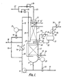
- a stainless steel reactor 1 is provided with an upper stainless steel grid 2 which supports an upper bed 3 of a granular aldehyde hydrogenation catalyst.
- This catalyst is a prereduced nickel on alumina catalyst in the form of 1/16 inch (1.6 mm) spheres containing 61% of nickel (calculated as metal) in the 50% reduced form and having a surface area of 140 m2/g as measured by the so-called BET method.
- Reactor 1 is of enlarged diameter at its lower end. This enlarged diameter lower end is fitted with a lower stainless steel grid 4 which supports a lower bed 5 of the same nickel catalyst. Thermocouples (not shown) are buried in catalyst beds 3 and 5 and reactor 1 is thermally insulated. Steam heating coils (not shown) are provided under the thermal insulation in order to assist in heating reactor 1 at start up.
- Layers of open-celled honeycomb grid material may be laid one on top of one another on top of grids 2 and 4 as the respective bed is loaded up with catalyst, each layer being offset from the layer below it so as to assist in even distribution of liquid over the entire bed and to avoid "channelling" of gas through the bed.
- the space 6 below lower grid 4 is used to collect liquid emerging from the bottom of second bed 5. Such liquid is withdrawn by way of line 7 and is recycled by means of pump 8 and lines 9 and 10 through heat exchanger 11 and then through line 12 to a static liquid distributor 13 positioned above upper bed 3 at the top of reactor 1.
- Reference numeral 14 indicates a feed line for heat exchanger 11 for supply of a heating medium (e.g. steam) or cooling water as need arises.
- Heat exchanger 11 can be bypassed by means of by pass line 15, flow through which is controlled by means of a valve 16 coupled to a temperature controller 17 which monitors the temperature in line 12.
- Aldehyde to be hydrogenated is supplied in line 18 and admixed with the liquid exiting heat exchanger 11.
- the resulting feed solution which typically contains about 10% w/w aldehyde is passed by way of line 12 to the top of catalyst bed 3 at a flow rate corresponding to a superficial liquid velocity down through the catalyst bed 3 of from about 1.5 cm/sec to about 3 cm/sec.
- a liquid intermediate reaction product containing typically less than about 1000 ppm aldehyde emerges from the bottom of bed 3 at substantially the same rate as the flow rate in line 12 and passes down through catalyst bed 5. Because catalyst bed 5 is of larger diameter than bed 3 the superficial liquid velocity through bed 5 is less than that through bed 3, typically from about 0.25 cm/sec to about 1.0 cm/sec. Alcohol hydrogenation product is withdrawn by way of line 19 under the control of valve 20 which is itself controlled by means of a level controller 21 arranged to monitor the liquid level in bottom space 6 of reactor 1.
- Hydrogen-containing gas from a pressure swing adsorption unit (not shown) is supplied to reactor 1 in line 22.
- a major part of the gas flows in line 23 to the top of reactor 1 under the control of a flow controller 24 whilst the remainder is fed by way of line 25 under the control of a further flow controller 26 to an upper part of the bottom space 6 at a point above the liquid level in bottom space 6.
- Flow controllers 24 and 26 are set so that the gas flow rate downwards through catalyst bed 3 at its upper face corresponds to a flow of hydrogen that is about 105% of the stoichiometric quantity of hydrogen required to hydrogenate to alcohol all the aldehyde supplied in line 18.
- a gas purge stream is taken from the space 27 between the two catalyst beds 3 and 5 in line 28. This is passed through a condenser 29 supplied with cooling water in line 30. Condensate is collected in drum 31 and is returned to reactor 1 in line 32. The resulting purge gas stream is taken in line 33 and passed through a further condenser 34 which is supplied with refrigerant in line 35. Pressure control valve 36 is used to control the pressure within the apparatus and hence the rate of withdrawal of purge gas in line 37.
- Reference numeral 38 indicates a static liquid distributor for distributing evenly across the top of lower bed 5 liquid that exits upper bed 3.
- Line 39 and valve 40 are used for initial charging of the reactor 1 with liquid.
- Reference numeral 41 indicates an optional internal cooling coil which is supplied with cooling water in line 42.
- honeycomb grid material in bed 5 which has been mentioned above is desirable as an upward flow of hydrogen containing gas is contacting a downflowing liquid; in this case there is a distinct tendency, in the absence of such honeycomb grid material, for the gas to flow up the central axis of the bed and for the liquid to flow down the walls.
- honeycomb grid material or of a similar liquid flow distribution material within catalyst bed 5 helps to obviate this tendency and to promote proper countercurrent flow through bed 5.
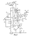
- the plant of Figure 2 has two separate reactors 43, 44 each containing a respective catalyst bed 3, 5.
- Reactor 44 is of larger diameter than reactor 43.
- Liquid intermediate reaction product emerging from the bottom of first catalyst bed 3 collects in the bottom of reactor 43 and passes by way of line 45 to the top of reactor 44.
- Purge gas is taken from reactor 43 in line 46 and from reactor 44 in line 47 which joins line 46 to form line 48 which leads in turn to condenser 29.
- Condensate is returned via line 32 from drum 31 to the top of reactor 44.
- the apparatus of Figure 2 permits operation of the two reactors 43 and 44 at different pressures; in this case a valve (not shown) can be provided in one or both of lines 46 and 47 and a pump (not shown) can be provided, if necessary, in line 32.
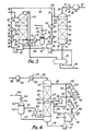
- a first reactor 51 is provided with an upper grid 52 which supports an upper bed 53 of a granular aldehyde hydrogenation catalyst.
- This catalyst is a prereduced nickel on alumina catalyst in the form of 1/16 inch (1.6 mm) spheres containing 61% of nickel (calculated as metal) in the 50% reduced form and having a surface area of 140 m2/g as measured by the co-called BET method.
- First reactor 51 is also fitted with a lower grid 54 which supports a lower bed 55 of the same nickel catalyst.
- Thermocouples (not shown) are buried in catalyst beds 53 and 55 and reactor 51 is thermally insulated.
- Steam heating coils (not shown) are provided under the thermal insulation in order to assist in heating reactor 51 at start up.
- layers of honeycomb grid material can optionally be introduced into each bed of catalyst as beds 53 and 55 are loaded into the reactor 51 in order to assist in promoting even distribution of liquid throughout the respective bed in operation of the plant.
- the space 56 below lower grid 54 is used to collect liquid emerging from the bottom of second bed 55. Such liquid is withdrawn by way of line 57 and is recycled by means of pump 58 and line 59 through heat exchanger 60. It is then fed through line 61 to a second heat exchanger 62 from which it is fed by way of lines 63, 64 to a static liquid distributor 65 positioned above upper bed 53 at the top of first reactor 51.
- Reference numeral 66 indicates a feed line for heat exchanger 11 for supply of a heating medium (e.g. steam) or cooling water as need arises.
- Heat exchanger 62 is provided with a steam heating line 67.
- Aldehyde to be hydrogenated is supplied in line 68 and admixed with the liquid exiting heat exchanger 62. This is mainly product alcohol, but still contains a minor amount of hydrogenatable material. It acts as a diluent for the aldehyde.
- the rate of recycle in line 64 is selected so as to produce, upon admixture with the incoming aldehyde in line 68, a solution of aldehyde in the product alcohol which typically lies in the range of from about 5 mole % up to about 30 mole % and is selected such that the superficial liquid velocity down through catalyst beds 53 and 55 is in the range of from about 1.5 cm/sec to about 3 cm/sec.
- Part of the recycle stream in line 63 is withdrawn by way of line 69 and is passed by way of line 70 to a static liquid distributor 71 fitted near the top of a second reactor 72.
- Hydrogen-containing gas is supplied to first reactor 51 in line 73.
- the source of such hydrogen-containing gas will be described further below.
- a gas purge stream is taken from the space 56 below catalyst bed 55 in line 74. This is passed through a condenser 75 supplied with cooling water in line 76. Condensate is collected in gas-liquid separator 77 and is returned to line 57 in line 78. Reference numeral 79 indicates a mist eliminator pad. The resulting purge gas stream is taken in line 80 and is passed through a vent valve 81 which is used to control the pressure within the apparatus and hence the rate of discharge of purge gas in line 82.
- Second reactor 72 is provided with an upper grid 83 which supports an upper bed 84 of hydrogenation catalyst and with a lower grid 85 which supports a lower bed 86 of the same catalyst.
- the catalyst of beds 84 and 86 may be the same as that of beds 53 and 55.
- Layers of honeycomb grid material may optionally be included in beds 84 and 86 to assist in obtaining even liquid distribution therethrough.
- Make up hydrogen-containing feed gas is supplied to the plant in line 87 from a pressure swing adsorption unit (not shown), is compressed (if necessary) by means of gas compressor 88 and is then passed by way of heat exchanger 89 and line 90 to the upper end of second reactor 72.
- Reference numeral 91 indicates a steam heating line.
- the gas from line 90 and the feed in line 70 flow in cocurrent downwardly through second reactor 72.
- the rate of supply of make up gas is controlled so as to correspond to about 105% of the stoichiometric quantity of hydrogen required to hydrogenate to product alcohol all of the aldehyde supplied in line 68 after allowance is made for dissolved hydrogen leaving the system in the product stream in line 96.
- Liquid product alcohol which collects in drum 95 is recovered in line 96 and passed on for product purification in conventional manner, e.g. distillation in one or more fractional distillation stages.
- Second reactor 72 can be operated, as described above, on a once-through basis as a single pass reactor.
- the incoming intermediate reaction product in line 69 can be admixed with recycled product from product recovery drum 95.
- a bypass line 97 is provided to enable recycle to be effected by means of recycle pump 98.
- Reference numerals 154 and 155 indicate heating or cooling lines for heat exchangers 150 and 152 respectively, by means of which temperature control of the liquid supplied in line 70 can be controlled.
- Pump 98 and heat exchangers 150 and 152 can be used at start up of the plant to warm up the catalyst beds 84 and 86 by circulating alcohol through reactor 72 prior to introduction of aldehyde to the plant.
- Heat exchangers 60 and 62 and pump 58 can be used in a similar way to circulate alcohol through reactor 51 and warm its catalyst beds 53 and 55 to the desired starting temperature.
- Product alcohol can be supplied to reactor 51 from product recovery drum 95, using pump 98, by way of line 156 under the control of valve 157.
- a secondary feed of aldehyde can be supplied by way of line 158, e.g. at start up of the plant.
- the apparatus of Figure 3 permits operation of the reactor 51 at a different lower pressure than reactor 72; in this case a pressure let down valve (not shown) can be provided in line 73 and a pump (not shown) can be provided in line 69.
- reactor 72 can be operated at a lower pressure than reactor 51; in this case a compressor (not shown) is provided in line 73 and a valve (also not shown) in line 69.
- the plant of Figure 4 has a single reactor 101 containing two hydrogenation catalyst beds 102 and 103.
- each bed may optionally include layers of honeycomb grid material to assist in promoting even distribution of liquid throughout the bed and to avoid "channelling" of gas through the bed.
- Catalyst bed 102 constitutes a first hydrogenation zone and catalyst bed 103 a second hydrogenation zone.
- Aldehyde to be hydrogenated is supplied in line 104 and hydrogen-containing feed gas is supplied from a pressure swing adsorption unit (not shown) in line 105 in an amount corresponding to about 105% of the stoichiometric quantity of hydrogen required to hydrogenate all of the aldehyde supplied in line 104 to product alcohol.
- the aldehyde feed flows from line 104 in line 106 and is admixed with a recycled alcohol stream in line 107.
- the admixed stream containing typically from about 5 mole % to about 30 mole % aldehyde in a predominantly alcohol diluent, is fed in line 108 to a static liquid distributor 109 above catalyst bed 102.
- the flow rate is sufficient to correspond to a superficial liquid velocity down catalyst bed 102 of from about 1.5 cm/sec to about 3 cm/sec.
- Intermediate reaction product is collected at the bottom of reactor 101 and is pumped by way of line 110, pump 111 and line 112 to a heat exchanger 113.
- the liquid intermediate reaction product which contains typically from about 0.1 mole % to about 5 mole % chemically unsaturated hydrogenatable organic material, is fed in line 114 to a further heat exchanger 115.
- Reference numeral 116 and 117 indicate respective heating or cooling lines for heat exchangers 113 and 115.
- the liquid intermediate reaction product in line 118 is fed in part in line 107 as the recycle stream to catalyst bed 102 and in part via lines 119 and 120 to a further static liquid distributor 121 fitted above catalyst bed 103.
- the superficial liquid velocity of the liquid flowing into catalyst bed 103 is from about 1.5 cm/sec to about 3 cm/sec.
- the chemically unsaturated hydrogenatable organic material remaining in the intermediate reaction product is substantially all hydrogenated to product alcohol in passage through catalyst bed 103.
- Substantially pure alcohol is recovered in line 122 from chimney tray 123 and is pumped by means of pump 124 and lines 125 and 126 to a conventional alcohol purification section (not shown). If desired, part of the product alcohol can be passed by way of line 127 through heat exchangers 128 and 129, whose heating or cooling lines are indicated at 130 and 131 respectively, to line 132 for recycle to liquid distributor 121.
- the hydrogen-containing feed gas in line 105 is compressed as necessary by means of gas compressor 133, heated in heat exchanger 134, whose steam heating line is indicated at 135, and supplied in line 136 to the top of reactor 101 above catalyst bed 103 at a rate corresponding to a superficial gas velocity at the upper surface of catalyst bed 103 of from about 1 cm/sec to about 4 cm/sec.
- Gas emerging from the bottom of catalyst bed 103 passes through an orifice 137 in chimney tray 123 and into catalyst bed 102.
- the superficial gas velocity at the upper surface of catalyst bed 102 is similarly in the range of from about 1 cm/sec to about 4 cm/sec.
- a purge gas stream is taken from the bottom of reactor 101 below catalyst bed 102 in line 138 and is passed through a condenser 139 which is supplied with cooling water in line 140.
- the cooled gas is passed in line 141 to a gas-liquid separator 142 which is fitted with a spray eliminator pad 143.
- the purge gas passes out in line 144 through control valve 145 to a vent line 146.
- the condensate is returned from gas-liquid separator 142 to reactor 101 in line 147.
- Reference numerals 148 and 149 represent a bypass line and bypass valve respectively for use at start up of the plant.
- Typical operating conditions in the plants of Figures 1 to 4 include use of an inlet temperature to each catalyst bed in the range of from about 100°C to about 130°C and a pressure of from about 5 bar to about 50 bar.
- concentration of aldehyde in the feed solution to each catalyst bed is such as to produce an adiabatic temperature rise across each bed of no more than about 20°C.
- Figure 5 illustrates a modified form of plant in which an added diluent is used.
- This form of plant is useful, for example, in the case in which the presence of an added adjuvant is desirable, such as ammonia in the hydrogenation of a nitro compound (e.g. nitrobenzene).
- an added adjuvant such as ammonia in the hydrogenation of a nitro compound (e.g. nitrobenzene).
- Material to be hydrogenated such as nitrobenzene
- a mixing device 202 to which is also fed in line 203 a mixture of make up diluent and adjuvant, such as a solution of ammonia in ethanol (containing some water), from line 204 as well as recycled diluent/adjuvant mixture in line 205.
- the resulting dilute nitrobenzene solution is fed to heater 206 in line 207 and admixed with make up hydrogen in line 208.
- Reference numeral 209 indicates a steam heating line for heater 206.
- the mixture of hydrogen, nitrobenzene, ammonia and ethanol flows in line 210 to hydrogenation zone 211.
- This can be a single reactor or a pair of reactors as used in the plant of one of Figures 1 to 4.
- layers of open-celled honeycomb material can be incorporated into the, or into each, catalyst bed of hydrogenation zone 211 in order to promote even co-current flow of liquid and gas downward through the bed.
- the liquid flow rate in line 207 is controlled so as to provide a superficial liquid velocity down through the or each bed of catalyst of from about 1.5 cm/sec to about 3 cm/sec, whilst the gas flow rate in line 208 is adjusted to provide at the operating pressure and temperature of the plant an amount of hydrogen equivalent to 115% of the stoichiometrically required amount.
- the resulting condensate collects in drum 222; part is returned to column 219 in line 223 as a reflux stream whilst the rest is recycled in line 224 by means of pump 225 to form the recycle stream in line 205.
- Reference numeral 226 indicates a gas vent line to condensate drum 222, whilst reference numeral 227 indicates the cooling water supply line for condenser 221.
- the bottom product from column 219 in line 228 consists of substantially nitrobenzene-free aniline containing a minor amount of ethanol and water produced in the reaction. Part is recycled to column 219 by way of line 229 and column reboiler 230 whose steam supply line is indicated at 231. The remainder is passed on for further purification and storage in line 232.
- mixing device 202 is omitted and lines 201 and 204 are connected to line 224 upstream from pump 225 which then serves as a mixing device.
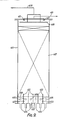
- Reactor 301 contained a bed 303 of catalyst supported on a layer 304 of 1.6 mm diameter glass beads 2 cm deep which was itself supported on a stainless steel mesh grid 305 some 10 cm above the base of reactor 301.
- the volume of catalyst bed 303 was 52.3 ml and the catalyst was a pre-reduced and air stabilised nickel on alumina catalyst containing 61% w/w of nickel (calculated as metal) in the 50% reduced form and having a surface area of 140 m2/g as measured by the socalled BET method.
- the physical form of the catalyst was near spherical granules of a nominal 1/16 inch (1.6 mm) diameter; the actual size range limits of the particles was from 1.4 mm to 2.36 mm as determined by sieve analysis.
- the upper portion of reactor 301 was filled with a layer 306 of 1.6 mm diameter glass beads; this layer 306 ensured that the temperature of the feed solution and entrained hydrogen supplied to catalyst bed 303 could be controlled to a pres
- Reactor 301 was also fitted with a thermocouple pocket 307 of small diameter for a thermocouple 308. During the packing procedure it was determined that the depth of catalyst bed 303 was 10.5 cm. Liquid could be withdrawn from the bottom of reactor 301 in line 309 by means of pump 310 and recycled to the top of reactor 301 in line 311. The rate of recycle of liquid in line 311 could be measured using a mass flow meter (not shown). Aldehyde feed could be supplied to the apparatus from a burette (not shown) in line 312 by means of a feed pump (not shown). Hydrogen could be supplied from a storage cylinder via a pressure let down valve and a flow controller (neither of which is shown) in line 313.
- a mixture of gas and liquid could also be withdrawn from reactor 301 by means of an overflow pipe 314 and passed in line 315 to a gas/liquid separation vessel 316.
- Pressure control valve 317 allowed a purge gas stream to be let down to atmospheric pressure and passed in line 318 to a wet gas meter (not shown) before being vented to the atmosphere.
- Liquid product could be removed from the system in line 319 by means of a pressure let down valve 320 operating under the influence of a liquid level controller 321. Samples of this liquid product were analysed by gas-liquid chromatography from time to time. Such analysis was repeated after any change in operating conditions had been effected until the results showed that steady state conditions had been re-established.
- the whole apparatus was positioned in a fume cupboard supplied with warm air at 40°C to eliminate any danger of blockage of lines due to solidification of n -tridecanol (m.p. 32-33°C).
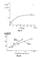
- [-CHO] mean (% w/w) ⁇ [-CHO] (% w/w) Liquid recycle rate (1/hr) 1 10.58 0.55 25.8 2 4.41 0.30 25.8 3 1.94 0.16 25.8 4 0.98 0.08 25.8 5 31.56 0.71 25.8 6 30.76 0.72 25.8 7 31.99 1.38 13.0 8 33.93 0.66 25.8 9 28.18 3.76 5.1 10 1.64 0.16 25.8
- Examples 1 to 5 and 10 were all carried out with a liquid recycle rate of 25.8 1/hr and a hydrogen purge rate of 19.8 1/hr so that these data define the relationship between the amount of n -aldehyde converted in passage through reactor 301, i.e. ⁇ [-CHO], and the n -aldehyde concentration, [-CHO] mean , within the reactor 301 under these conditions of hydrogen flow and liquid recycle rate.
- a considerable reduction in hydrogen purge flow rate to 3.9 1/hr makes very little difference to the amount of n - aldehyde converted in passage through reactor 301, i.e. ⁇ [-CHO], as can be seen by comparison of Examples 5 and 8.
- the data defining the curve of Figure 7 represent a scan of different horizontal segments of catalyst in a large reactor and can be used to calculate the depth of catalyst bed required for a commercial reactor operating under appropriate conditions including aldehyde concentration, flow rate and temperature according to the teachings of the invention.
- Example 9 in some measure represents the situation arising in a "local low flow volume element" of a large catalyst bed operated at low superficial liquid velocities.
- Figure 8 summarises the results of Examples 31 to 36. This is a graph of the amount of aldehyde converted per hour in the apparatus plotted against the concentration of aldehyde in the liquid phase exiting the reactor. The numerals on the graph indicate the numbers of the respective Examples. It will be seen that two separate curves can be plotted, one representing the data obtained when no diluent (i.e. n -tetradecane) has been added and the other when a diluent is used.
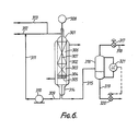
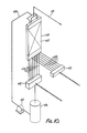
- FIG. 9 This comprises a rectangular section column 401 which was constructed from 1.25 mm thick "Perspex" (Registered Trade Mark) sheet so as to enable its contents to be viewed. Partitions 402 near its base divided the base of the column 401 into six bays 403, each of which had a corresponding outlet line 404 for water and an outlet line 405 for air.
- Perspex Registered Trade Mark
- Reference numeral 406 indicates a perforated support for a bed 407 of particles intended to simulate a hydrogenation catalyst.
- Bed 407 consisted of impervious ceramic balls of nominal size 2.4 to 4 mm, more than 80% of which were 3 mm or less in diameter.
- Water was supplied in line 408 to a bar distributor 409 above the top of the bed 407, whilst air was fed in line 410 from a compressor (not shown) to inlets 411 at the top of column 401.
- Bed 407 measured approximately 460 mm x 75 mm x 1425 mm and was topped with a layer of 12.7 mm diameter polypropylene balls approximately 200 mm deep which was intended to enhance the uniformity of distribution of the water over the top of bed 407.
- each bay 403 was conducted along a line 404 of standard length to a corresponding turbine meter in a bank 412 of turbine meters, each receiving water from a respective bay 403.
- air from each bay 403 was conducted along a line 405 of standard length to a corresponding turbine meter in a bank 413 of such turbine meters, each receiving air from a respective bay 403.
- the signals from the two banks of meters 412 and 413 were transmitted to respective data loggers (not shown).
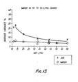
- Measurements were made with water flow rates in line 408 of 30 to 55 litres per minute and air flow rates in line 410 of 59 to 5 litres per minute. These flow rates were chosen to simulate a range of flow rates likely to be encountered in a commercial hydrogenation reactor operated in accordance with the teachings of this invention and correspond to a liquid phase superficial velocity of 1.43 to 2.63 cm/sec and a gas phase superficial velocity of 0.096 to 2.01 cm/sec.
Landscapes
- Chemical & Material Sciences (AREA)
- Organic Chemistry (AREA)
- Chemical Kinetics & Catalysis (AREA)
- Organic Low-Molecular-Weight Compounds And Preparation Thereof (AREA)
- Low-Molecular Organic Synthesis Reactions Using Catalysts (AREA)
- Catalysts (AREA)
- Glass Compositions (AREA)
- Iron Core Of Rotating Electric Machines (AREA)
- Valve Device For Special Equipments (AREA)
- Valve-Gear Or Valve Arrangements (AREA)
- Pharmaceuticals Containing Other Organic And Inorganic Compounds (AREA)
- Lock And Its Accessories (AREA)
- Production Of Liquid Hydrocarbon Mixture For Refining Petroleum (AREA)
Priority Applications (1)
| Application Number | Priority Date | Filing Date | Title |
|---|---|---|---|
| AT88311188T ATE74898T1 (de) | 1987-12-02 | 1988-11-25 | Hydrierungsverfahren. |
Applications Claiming Priority (2)
| Application Number | Priority Date | Filing Date | Title |
|---|---|---|---|
| GB8728156 | 1987-12-02 | ||
| GB878728156A GB8728156D0 (en) | 1987-12-02 | 1987-12-02 | Process |
Publications (2)
| Publication Number | Publication Date |
|---|---|
| EP0319208A1 true EP0319208A1 (fr) | 1989-06-07 |
| EP0319208B1 EP0319208B1 (fr) | 1992-04-15 |
Family
ID=10627851
Family Applications (2)
| Application Number | Title | Priority Date | Filing Date |
|---|---|---|---|
| EP88311188A Expired - Lifetime EP0319208B1 (fr) | 1987-12-02 | 1988-11-25 | Procédé d'hydrogénation |
| EP88910086A Pending EP0393093A1 (fr) | 1987-12-02 | 1988-11-25 | Procede d'hydrogenation |
Family Applications After (1)
| Application Number | Title | Priority Date | Filing Date |
|---|---|---|---|
| EP88910086A Pending EP0393093A1 (fr) | 1987-12-02 | 1988-11-25 | Procede d'hydrogenation |
Country Status (15)
| Country | Link |
|---|---|
| US (1) | US5093535A (fr) |
| EP (2) | EP0319208B1 (fr) |
| JP (1) | JP2675171B2 (fr) |
| KR (1) | KR960004878B1 (fr) |
| CN (1) | CN1024535C (fr) |
| AT (1) | ATE74898T1 (fr) |
| AU (1) | AU2725688A (fr) |
| CA (1) | CA1328117C (fr) |
| DE (1) | DE3870171D1 (fr) |
| ES (1) | ES2032023T3 (fr) |
| GB (1) | GB8728156D0 (fr) |
| IN (1) | IN172818B (fr) |
| MX (1) | MX170124B (fr) |
| WO (1) | WO1989005286A1 (fr) |
| ZA (1) | ZA889062B (fr) |
Cited By (13)
| Publication number | Priority date | Publication date | Assignee | Title |
|---|---|---|---|---|
| WO1994006738A1 (fr) * | 1992-09-14 | 1994-03-31 | Unichema Chemie B.V. | Procede de production d'alcools |
| EP0992475A2 (fr) * | 1998-09-28 | 2000-04-12 | Degussa-Hüls Aktiengesellschaft | Procédé de préparation d'alcools par hydrogénation catalytique des aldéhydes ou cétones |
| US6262317B1 (en) | 1996-10-10 | 2001-07-17 | Basf Aktiengesellschaft | Process for preparing 1,4-butanediol by catalytic hydrogenation of 1,4-butinediol |
| US6297409B1 (en) | 1999-02-17 | 2001-10-02 | Roquette Freres | Continuous process for the preparation of a high-purity hydrogenated ose by catalytic hydrogenation |
| US6632414B2 (en) | 2001-03-30 | 2003-10-14 | Corning Incorporated | Mini-structured catalyst beds for three-phase chemical processing |
| US6716339B2 (en) | 2001-03-30 | 2004-04-06 | Corning Incorporated | Hydrotreating process with monolithic catalyst |
| US7524996B2 (en) | 2005-09-06 | 2009-04-28 | Basf Aktiengesellschaft | Method for the separation of polymeric by-products from 1,4-butynediol |
| US7538254B2 (en) | 2005-09-06 | 2009-05-26 | Basf Aktiengesellschaft | Method for the separation of polymeric by-products from 1,4-butynediol |
| US7759531B2 (en) | 2007-02-15 | 2010-07-20 | Basf Aktiengesellschaft | Process for preparing 1,4-butanediol |
| WO2011115695A1 (fr) | 2010-03-15 | 2011-09-22 | Exxonmobil Chemical Patents Inc. | Procédé de production d'alcools |
| CN103506125A (zh) * | 2012-06-21 | 2014-01-15 | 中国石油化工股份有限公司 | 用于丙醛气相加氢制丙醇的催化剂及其制备方法 |
| CN104557456A (zh) * | 2013-10-22 | 2015-04-29 | 中国石油化工股份有限公司 | 一种丁醛液相加氢生成丁醇的方法 |
| EP3045439A1 (fr) | 2015-01-19 | 2016-07-20 | Evonik Degussa GmbH | Fabrication combinee de butene et d'octene a partir d'ethylene |
Families Citing this family (62)
| Publication number | Priority date | Publication date | Assignee | Title |
|---|---|---|---|---|
| GB8917862D0 (en) * | 1989-08-04 | 1989-09-20 | Davy Mckee London | Process |
| US5360920A (en) * | 1992-08-07 | 1994-11-01 | The Procter & Gamble Company | Hydrogenation in a plate heat exchanger |
| JP2526404B2 (ja) * | 1993-10-15 | 1996-08-21 | 工業技術院長 | 触媒反応方法 |
| US5744655A (en) * | 1996-06-19 | 1998-04-28 | The Dow Chemical Company | Process to make 2,3-dihalopropanols |
| US5877358A (en) * | 1996-09-23 | 1999-03-02 | Exxon Chemical Patents Inc. | Alcohol hydrogenation with intermediate recycle |
| DE19933348B4 (de) * | 1999-07-16 | 2005-11-17 | Oxeno Olefinchemie Gmbh | Verfahren zur Reduzierung oxidischer Hydrierkontakte |
| US7297738B2 (en) | 2001-09-25 | 2007-11-20 | Exxonmobil Chemical Patents Inc. | Plasticized polyvinyl chloride |
| US7279018B2 (en) * | 2002-09-06 | 2007-10-09 | Fortum Oyj | Fuel composition for a diesel engine |
| JP4802497B2 (ja) * | 2002-11-27 | 2011-10-26 | 新日本理化株式会社 | 水素化反応方法 |
| CN1849383B (zh) * | 2003-09-13 | 2010-11-24 | 埃克森美孚化学专利公司 | 用于机动车齿轮的润滑组合物 |
| DE602004017773D1 (de) * | 2003-11-13 | 2008-12-24 | Neste Oil Oyj | Verfahren zur hydrierung von olefinen |
| US7422904B2 (en) * | 2005-02-04 | 2008-09-09 | Exxonmobil Chemical Patents Inc. | Method of operating a fixed bed reactor under predetermined hydraulic conditions |
| US8022258B2 (en) | 2005-07-05 | 2011-09-20 | Neste Oil Oyj | Process for the manufacture of diesel range hydrocarbons |
| US7772412B2 (en) * | 2006-01-26 | 2010-08-10 | Battelle Memorial Institute | Methods for dehydration of sugars and sugar alcohols |
| US7615652B2 (en) * | 2006-01-26 | 2009-11-10 | Battelle Memorial Institute | Two-stage dehydration of sugars |
| US7649099B2 (en) * | 2006-01-26 | 2010-01-19 | Battelle Memorial Institute | Method of forming a dianhydrosugar alcohol |
| US7728156B2 (en) * | 2006-01-26 | 2010-06-01 | Battelle Memorial Institute | Method of performing sugar dehydration and catalyst treatment |
| JP2009544649A (ja) * | 2006-07-25 | 2009-12-17 | ビーエーエスエフ ソシエタス・ヨーロピア | 溶剤を含有する水素化搬出物を後処理する方法 |
| DE102007011483A1 (de) * | 2007-03-07 | 2008-09-18 | Evonik Degussa Gmbh | Verfahren zur Herstellung von 3-Aminomethyl-3,5,5-trimethylcyclohexylamin |
| WO2009009322A1 (fr) * | 2007-07-06 | 2009-01-15 | Best Energies, Inc. | Équipement intégré pour produire de l'alcool en utilisant une fermentation homoacidogénique |
| US7811447B2 (en) * | 2007-08-01 | 2010-10-12 | Uop Llc | Method of transferring particles from one pressure zone to another pressure zone |
| US8003834B2 (en) * | 2007-09-20 | 2011-08-23 | Uop Llc | Integrated process for oil extraction and production of diesel fuel from biorenewable feedstocks |
| US8575409B2 (en) | 2007-12-20 | 2013-11-05 | Syntroleum Corporation | Method for the removal of phosphorus |
| US20090300971A1 (en) | 2008-06-04 | 2009-12-10 | Ramin Abhari | Biorenewable naphtha |
| US8581013B2 (en) | 2008-06-04 | 2013-11-12 | Syntroleum Corporation | Biorenewable naphtha composition and methods of making same |
| US7982079B2 (en) * | 2008-09-11 | 2011-07-19 | Uop Llc | Integrated process for production of diesel fuel from renewable feedstocks and ethanol denaturizing |
| US8231804B2 (en) | 2008-12-10 | 2012-07-31 | Syntroleum Corporation | Even carbon number paraffin composition and method of manufacturing same |
| CN101787305B (zh) * | 2009-01-23 | 2013-03-20 | 中国石油化工股份有限公司 | 一种液相循环加氢处理方法和反应系统 |
| US8394900B2 (en) | 2010-03-18 | 2013-03-12 | Syntroleum Corporation | Profitable method for carbon capture and storage |
| EP2489720A1 (fr) | 2011-02-15 | 2012-08-22 | Neste Oil Oyj | Utilisation d'huile renouvelable dans un procédé d'hydrotraitement |
| NL2008611C2 (nl) * | 2012-04-05 | 2013-10-09 | Mooij Agro B V | Inrichting voor het aan een gasstroom onderwerpen van producten, bijvoorbeeld ten behoeve van een droog- of vries-procédé. |
| CN103773475B (zh) * | 2012-10-24 | 2015-09-02 | 中国石油化工股份有限公司 | 一种气相、液相组合加氢工艺方法 |
| CN103773471B (zh) * | 2012-10-24 | 2015-08-12 | 中国石油化工股份有限公司 | 一种气相、液相联合加氢工艺方法 |
| EP2757088B1 (fr) * | 2013-01-22 | 2016-08-03 | Covestro Deutschland AG | Procédé destiné à la fabrication d'amines aromatiques |
| CN103965953B (zh) * | 2013-01-30 | 2015-07-22 | 中国石油天然气股份有限公司 | 一种馏分油两相加氢反应器和加氢工艺方法 |
| US9328303B2 (en) | 2013-03-13 | 2016-05-03 | Reg Synthetic Fuels, Llc | Reducing pressure drop buildup in bio-oil hydroprocessing reactors |
| US8969259B2 (en) | 2013-04-05 | 2015-03-03 | Reg Synthetic Fuels, Llc | Bio-based synthetic fluids |
| CN105555752A (zh) * | 2013-09-13 | 2016-05-04 | 因温斯特技术公司 | 使二腈氢化以便制备二胺 |
| CN103566837B (zh) * | 2013-11-13 | 2015-09-30 | 山西大学 | 一种适用于加氢放热反应的外循环反应装置 |
| CN106536462B (zh) * | 2014-02-07 | 2019-10-18 | 科慕埃弗西有限公司 | 用于制备z-1,1,1,4,4,4-六氟-2-丁烯的一体化方法 |
| CN106061930A (zh) * | 2014-02-25 | 2016-10-26 | 拜奥开姆泰克股份公司 | 用于制备乙二醇流的连续方法 |
| KR101612099B1 (ko) * | 2014-06-25 | 2016-04-14 | (주)테크윈 | 전기분해장치 |
| KR101600037B1 (ko) * | 2014-06-26 | 2016-03-07 | (주)테크윈 | 선박평형수 처리시스템 |
| DE102014223427A1 (de) | 2014-11-17 | 2016-05-19 | Hydrogenious Technologies Gmbh | Verfahren und Anlage zum Erzeugen und Speichern von Wasserstoff |
| CN104492445A (zh) * | 2014-12-18 | 2015-04-08 | 复旦大学 | 一种用于草酸二甲酯气相催化加氢合成乙二醇及乙醇酸甲酯的催化剂及其制备方法 |
| CA3229116A1 (fr) | 2015-06-30 | 2017-01-05 | Takeda Pharmaceutical Company Limited | Procede de production d'un compose pyrrole |
| BR112018009017B1 (pt) | 2015-11-10 | 2021-01-26 | Dow Technology Investments Llc | processo para produção de aldeídos |
| BR112018016320B1 (pt) | 2016-02-11 | 2022-07-12 | Dow Technology Investments Llc | Processo para converter olefinas em álcoois, éteres ou combinações dos mesmos |
| WO2017221261A1 (fr) * | 2016-06-23 | 2017-12-28 | Natco Pharma Limited | Procédé de préparation de pomalidomide et sa purification |
| CN109641743A (zh) * | 2016-08-30 | 2019-04-16 | 全耐塑料高级创新研究公司 | 用于在车辆上增大水溶液的尿素浓度的系统和方法 |
| WO2019020655A1 (fr) * | 2017-07-28 | 2019-01-31 | Hte Gmbh The High Throughput Experimentation Company | Dispositif et procédé pour la réaction catalytique de substances chimiques pour des temps de séjour de 0,1 à 10 secondes |
| WO2019245859A1 (fr) * | 2018-06-21 | 2019-12-26 | The J. David Gladstone Institutes | Génération d'une population de cellules de cerveau postérieur et d'organoïdes de type cerveau postérieur à partir de cellules souches pluripotentes |
| US11772082B1 (en) | 2018-06-21 | 2023-10-03 | Avn Corporation | Catalyst supports—composition and process of manufacture |
| CN109225073B (zh) * | 2018-09-17 | 2021-01-15 | 清华大学 | 一种微填充床内加氢反应装置及其进行加氢反应的方法 |
| CN111099965B (zh) * | 2018-10-25 | 2024-03-12 | 中国石油化工股份有限公司 | 一种1,5-戊二醇的液相加氢精制方法 |
| CN109908843B (zh) * | 2019-04-23 | 2019-12-31 | 宁波巨化新材料有限公司 | 丙醛加氢反应器 |
| CN112920015A (zh) * | 2019-12-06 | 2021-06-08 | 陶氏技术投资有限责任公司 | 用于精炼由醛的氢化衍生的醇的方法 |
| CN114929660A (zh) | 2019-12-19 | 2022-08-19 | 陶氏技术投资有限责任公司 | 用于制备异戊二烯和包含至少六个碳原子的单烯烃的方法 |
| WO2022066160A1 (fr) * | 2020-09-24 | 2022-03-31 | Iowa Corn Promotion Board | Procédés continus pour la conversion sélective de glucide producteur de l'aldohexose en éthylène glycol à l'aide de faibles concentrations de catalyseur rétro-aldolique |
| US11319269B2 (en) | 2020-09-24 | 2022-05-03 | Iowa Corn Promotion Board | Continuous processes for the selective conversion of aldohexose-yielding carbohydrate to ethylene glycol using low concentrations of retro-aldol catalyst |
| US11884614B2 (en) | 2022-05-26 | 2024-01-30 | Chevron Phillips Chemical Company Lp | Normal alpha olefin synthesis using decarbonylative olefination |
| WO2024026285A1 (fr) | 2022-07-27 | 2024-02-01 | Chevron Phillips Chemical Company Lp | Synthèse de n-heptane à partir d'oléfines et systèmes de production associés |
Citations (3)
| Publication number | Priority date | Publication date | Assignee | Title |
|---|---|---|---|---|
| DE2040501A1 (de) * | 1970-08-14 | 1972-02-17 | Basf Ag | Verfahren zur Durchfuehrung von exothermen Reaktionen zwischen einem Gas und einer Fluessigkeit |
| WO1987007598A1 (fr) * | 1986-06-03 | 1987-12-17 | Davy Mckee (London) Limited | Procede d'hydrogenation d'un compose organique insature |
| WO1988005767A1 (fr) * | 1987-02-06 | 1988-08-11 | Davy Mckee (London) Limited | Procede d'hydrogenation |
Family Cites Families (7)
| Publication number | Priority date | Publication date | Assignee | Title |
|---|---|---|---|---|
| GB1002372A (en) * | 1961-04-25 | 1965-08-25 | Chisso Corp | Process for continuously hydrogenating higher aldehydes in liquid phase |
| BE754868A (fr) * | 1969-08-16 | 1971-02-15 | Basf Ag | Procede pour la mise en oeuvre de reactions exothermiques entreun gaz et un liquide |
| DE2257673B1 (de) * | 1972-11-24 | 1974-03-28 | Verfahren zur herstellung von aliphatischen alkoholen | |
| JPS5812053A (ja) * | 1981-07-15 | 1983-01-24 | Nec Corp | 情報処理装置 |
| US4451677A (en) * | 1981-08-20 | 1984-05-29 | Davy Mckee (London) Limited | Multistage aldehyde hydrogenation |
| US4510092A (en) * | 1982-03-19 | 1985-04-09 | Uop Inc. | Continuous reduction of edible oils |
| US4626604A (en) * | 1985-09-11 | 1986-12-02 | Davy Mckee (London) Limited | Hydrogenation process |
-
1987
- 1987-12-02 GB GB878728156A patent/GB8728156D0/en active Pending
-
1988
- 1988-11-25 AU AU27256/88A patent/AU2725688A/en not_active Abandoned
- 1988-11-25 AT AT88311188T patent/ATE74898T1/de not_active IP Right Cessation
- 1988-11-25 EP EP88311188A patent/EP0319208B1/fr not_active Expired - Lifetime
- 1988-11-25 WO PCT/GB1988/001027 patent/WO1989005286A1/fr not_active Application Discontinuation
- 1988-11-25 ES ES198888311188T patent/ES2032023T3/es not_active Expired - Lifetime
- 1988-11-25 JP JP1505574A patent/JP2675171B2/ja not_active Expired - Fee Related
- 1988-11-25 KR KR1019890701448A patent/KR960004878B1/ko not_active IP Right Cessation
- 1988-11-25 DE DE8888311188T patent/DE3870171D1/de not_active Expired - Lifetime
- 1988-11-25 EP EP88910086A patent/EP0393093A1/fr active Pending
- 1988-11-25 US US07/476,453 patent/US5093535A/en not_active Expired - Lifetime
- 1988-11-30 IN IN853MA1988 patent/IN172818B/en unknown
- 1988-11-30 MX MX013998A patent/MX170124B/es unknown
- 1988-12-01 CA CA000584688A patent/CA1328117C/fr not_active Expired - Fee Related
- 1988-12-02 ZA ZA889062A patent/ZA889062B/xx unknown
- 1988-12-02 CN CN88108327A patent/CN1024535C/zh not_active Expired - Lifetime
Patent Citations (3)
| Publication number | Priority date | Publication date | Assignee | Title |
|---|---|---|---|---|
| DE2040501A1 (de) * | 1970-08-14 | 1972-02-17 | Basf Ag | Verfahren zur Durchfuehrung von exothermen Reaktionen zwischen einem Gas und einer Fluessigkeit |
| WO1987007598A1 (fr) * | 1986-06-03 | 1987-12-17 | Davy Mckee (London) Limited | Procede d'hydrogenation d'un compose organique insature |
| WO1988005767A1 (fr) * | 1987-02-06 | 1988-08-11 | Davy Mckee (London) Limited | Procede d'hydrogenation |
Cited By (18)
| Publication number | Priority date | Publication date | Assignee | Title |
|---|---|---|---|---|
| WO1994006738A1 (fr) * | 1992-09-14 | 1994-03-31 | Unichema Chemie B.V. | Procede de production d'alcools |
| US6262317B1 (en) | 1996-10-10 | 2001-07-17 | Basf Aktiengesellschaft | Process for preparing 1,4-butanediol by catalytic hydrogenation of 1,4-butinediol |
| EP0992475A2 (fr) * | 1998-09-28 | 2000-04-12 | Degussa-Hüls Aktiengesellschaft | Procédé de préparation d'alcools par hydrogénation catalytique des aldéhydes ou cétones |
| EP0992475A3 (fr) * | 1998-09-28 | 2000-05-17 | Degussa-Hüls Aktiengesellschaft | Procédé de préparation d'alcools par hydrogénation catalytique des aldéhydes ou cétones |
| US6441255B1 (en) | 1998-09-28 | 2002-08-27 | Degussa -Huls Ag | Method of producing alcohols by catalytic hydrogenation of aldehydes or ketones |
| US6297409B1 (en) | 1999-02-17 | 2001-10-02 | Roquette Freres | Continuous process for the preparation of a high-purity hydrogenated ose by catalytic hydrogenation |
| US6632414B2 (en) | 2001-03-30 | 2003-10-14 | Corning Incorporated | Mini-structured catalyst beds for three-phase chemical processing |
| US6716339B2 (en) | 2001-03-30 | 2004-04-06 | Corning Incorporated | Hydrotreating process with monolithic catalyst |
| US7524996B2 (en) | 2005-09-06 | 2009-04-28 | Basf Aktiengesellschaft | Method for the separation of polymeric by-products from 1,4-butynediol |
| US7538254B2 (en) | 2005-09-06 | 2009-05-26 | Basf Aktiengesellschaft | Method for the separation of polymeric by-products from 1,4-butynediol |
| US7572941B2 (en) | 2005-09-06 | 2009-08-11 | Basf Aktiengesellschaft | Method for the separation of polymeric by-products from 1,4-butynediol |
| US7605292B2 (en) | 2005-09-06 | 2009-10-20 | Basf Aktiengesellschaft | Method for the separation of polymeric by-products from 1,4-butynediol |
| US7759531B2 (en) | 2007-02-15 | 2010-07-20 | Basf Aktiengesellschaft | Process for preparing 1,4-butanediol |
| WO2011115695A1 (fr) | 2010-03-15 | 2011-09-22 | Exxonmobil Chemical Patents Inc. | Procédé de production d'alcools |
| US8871985B2 (en) | 2010-03-15 | 2014-10-28 | Exxonmobil Chemical Patents Inc. | Processes for the production of alcohols |
| CN103506125A (zh) * | 2012-06-21 | 2014-01-15 | 中国石油化工股份有限公司 | 用于丙醛气相加氢制丙醇的催化剂及其制备方法 |
| CN104557456A (zh) * | 2013-10-22 | 2015-04-29 | 中国石油化工股份有限公司 | 一种丁醛液相加氢生成丁醇的方法 |
| EP3045439A1 (fr) | 2015-01-19 | 2016-07-20 | Evonik Degussa GmbH | Fabrication combinee de butene et d'octene a partir d'ethylene |
Also Published As
| Publication number | Publication date |
|---|---|
| CN1033377A (zh) | 1989-06-14 |
| KR900700422A (ko) | 1990-08-13 |
| MX170124B (es) | 1993-08-09 |
| DE3870171D1 (de) | 1992-05-21 |
| EP0319208B1 (fr) | 1992-04-15 |
| GB8728156D0 (en) | 1988-01-06 |
| JPH03501483A (ja) | 1991-04-04 |
| CA1328117C (fr) | 1994-03-29 |
| WO1989005286A1 (fr) | 1989-06-15 |
| EP0393093A1 (fr) | 1990-10-24 |
| IN172818B (fr) | 1993-12-04 |
| ES2032023T3 (es) | 1993-01-01 |
| ATE74898T1 (de) | 1992-05-15 |
| KR960004878B1 (ko) | 1996-04-16 |
| CN1024535C (zh) | 1994-05-18 |
| JP2675171B2 (ja) | 1997-11-12 |
| ZA889062B (en) | 1989-08-30 |
| AU2725688A (en) | 1989-07-05 |
| US5093535A (en) | 1992-03-03 |
Similar Documents
| Publication | Publication Date | Title |
|---|---|---|
| EP0319208B1 (fr) | Procédé d'hydrogénation | |
| EP0300018B1 (fr) | Procede d'hydrogenation | |
| US7851221B2 (en) | Fixed bed reactor | |
| Østergaard | Gas-liquid-particle operations in chemical reaction engineering | |
| CA2327047A1 (fr) | Procede pour condensation catalytique d'aldols au moyen d'une reaction multiphases | |
| Mills et al. | Multiphase reaction engineering for fine chemicals and pharmaceuticals | |
| JPH01503454A (ja) | 不飽和有機化合物の水素化方法 | |
| EA024857B1 (ru) | Газожидкостный реактор и способ осуществления реакции в системе газ/жидкость | |
| US6878851B2 (en) | Process for the hydrogenation of acetone | |
| US7005554B2 (en) | Method for continuous hydrogenation of citronellal to form citronellol | |
| SU386899A1 (ru) | Способ получения высших алифатических спиртов | |
| SU806669A1 (ru) | Способ получени высших алифати-чЕСКиХ СпиРТОВ | |
| Acres | Trickle Column Reactors |
Legal Events
| Date | Code | Title | Description |
|---|---|---|---|
| PUAI | Public reference made under article 153(3) epc to a published international application that has entered the european phase |
Free format text: ORIGINAL CODE: 0009012 |
|
| AK | Designated contracting states |
Kind code of ref document: A1 Designated state(s): ES |
|
| 17P | Request for examination filed |
Effective date: 19891120 |
|
| 17Q | First examination report despatched |
Effective date: 19910730 |
|
| RBV | Designated contracting states (corrected) |
Designated state(s): AT BE CH DE ES FR GB IT LI LU NL SE |
|
| XX | Miscellaneous (additional remarks) |
Free format text: VERBUNDEN MIT 88910086.3/0393093 (EUROPAEISCHE ANMELDENUMMER/VEROEFFENTLICHUNGSNUMMER) DURCH ENTSCHEIDUNG VOM 11.11.91. |
|
| GRAA | (expected) grant |
Free format text: ORIGINAL CODE: 0009210 |
|
| RAP1 | Party data changed (applicant data changed or rights of an application transferred) |
Owner name: DAVY MCKEE (LONDON) LIMITED |
|
| AK | Designated contracting states |
Kind code of ref document: B1 Designated state(s): AT BE CH DE ES FR GB IT LI LU NL SE |
|
| REF | Corresponds to: |
Ref document number: 74898 Country of ref document: AT Date of ref document: 19920515 Kind code of ref document: T |
|
| XX | Miscellaneous (additional remarks) |
Free format text: VERBUNDEN MIT 88910086.3/0393093 (EUROPAEISCHE ANMELDENUMMER/VEROEFFENTLICHUNGSNUMMER) DURCH ENTSCHEIDUNG VOM 11.11.91. |
|
| REF | Corresponds to: |
Ref document number: 3870171 Country of ref document: DE Date of ref document: 19920521 |
|
| ITF | It: translation for a ep patent filed |
Owner name: STUDIO CONS. BREVETTUALE S.R.L. |
|
| ET | Fr: translation filed | ||
| REG | Reference to a national code |
Ref country code: ES Ref legal event code: FG2A Ref document number: 2032023 Country of ref document: ES Kind code of ref document: T3 |
|
| PLBI | Opposition filed |
Free format text: ORIGINAL CODE: 0009260 |
|
| PLBI | Opposition filed |
Free format text: ORIGINAL CODE: 0009260 |
|
| PLBI | Opposition filed |
Free format text: ORIGINAL CODE: 0009260 |
|
| 26 | Opposition filed |
Opponent name: HUELS AKTIENGESELLSCHAFT Effective date: 19921224 |
|
| 26 | Opposition filed |
Opponent name: EXXON CHEMICAL PATENTS INC. Effective date: 19930111 Opponent name: HUELS AKTIENGESELLSCHAFT Effective date: 19921224 |
|
| 26 | Opposition filed |
Opponent name: BASF AKTIENGESELLSCHAFT, LUDWIGSHAFEN Effective date: 19930114 Opponent name: EXXON CHEMICAL PATENTS INC. Effective date: 19930111 Opponent name: HUELS AKTIENGESELLSCHAFT Effective date: 19921224 |
|
| NLR1 | Nl: opposition has been filed with the epo |
Opponent name: HUELS AKTIENGESELSCHAFT |
|
| NLR1 | Nl: opposition has been filed with the epo |
Opponent name: BASF AG Opponent name: EXXON CHEMICAL PATENTS INC. |
|
| EPTA | Lu: last paid annual fee | ||
| PGFP | Annual fee paid to national office [announced via postgrant information from national office to epo] |
Ref country code: AT Payment date: 19941213 Year of fee payment: 7 |
|
| PGFP | Annual fee paid to national office [announced via postgrant information from national office to epo] |
Ref country code: CH Payment date: 19941214 Year of fee payment: 7 |
|
| PLAB | Opposition data, opponent's data or that of the opponent's representative modified |
Free format text: ORIGINAL CODE: 0009299OPPO |
|
| PGFP | Annual fee paid to national office [announced via postgrant information from national office to epo] |
Ref country code: LU Payment date: 19950101 Year of fee payment: 7 |
|
| EAL | Se: european patent in force in sweden |
Ref document number: 88311188.2 |
|
| R26 | Opposition filed (corrected) |
Opponent name: HUELS AKTIENGESELLSCHAFT * 930111 EXXON CHEMICAL P Effective date: 19921224 |
|
| PG25 | Lapsed in a contracting state [announced via postgrant information from national office to epo] |
Ref country code: LU Free format text: LAPSE BECAUSE OF NON-PAYMENT OF DUE FEES Effective date: 19951125 Ref country code: AT Effective date: 19951125 |
|
| PG25 | Lapsed in a contracting state [announced via postgrant information from national office to epo] |
Ref country code: LI Effective date: 19951130 Ref country code: CH Effective date: 19951130 |
|
| PGFP | Annual fee paid to national office [announced via postgrant information from national office to epo] |
Ref country code: BE Payment date: 19960109 Year of fee payment: 8 |
|
| REG | Reference to a national code |
Ref country code: CH Ref legal event code: PL |
|
| PG25 | Lapsed in a contracting state [announced via postgrant information from national office to epo] |
Ref country code: BE Effective date: 19961130 |
|
| BERE | Be: lapsed |
Owner name: DAVY MCKEE (LONDON) LTD Effective date: 19961130 |
|
| PGFP | Annual fee paid to national office [announced via postgrant information from national office to epo] |
Ref country code: SE Payment date: 19991124 Year of fee payment: 12 |
|
| PGFP | Annual fee paid to national office [announced via postgrant information from national office to epo] |
Ref country code: ES Payment date: 19991126 Year of fee payment: 12 |
|
| PGFP | Annual fee paid to national office [announced via postgrant information from national office to epo] |
Ref country code: FR Payment date: 19991130 Year of fee payment: 12 |
|
| PGFP | Annual fee paid to national office [announced via postgrant information from national office to epo] |
Ref country code: GB Payment date: 19991201 Year of fee payment: 12 |
|
| PGFP | Annual fee paid to national office [announced via postgrant information from national office to epo] |
Ref country code: DE Payment date: 19991207 Year of fee payment: 12 |
|
| PGFP | Annual fee paid to national office [announced via postgrant information from national office to epo] |
Ref country code: NL Payment date: 19991228 Year of fee payment: 12 |
|
| PLAB | Opposition data, opponent's data or that of the opponent's representative modified |
Free format text: ORIGINAL CODE: 0009299OPPO |
|
| R26 | Opposition filed (corrected) |
Opponent name: DEGUSSA-HUELS AKTIENGESELLSCHAFT PATENTE UND MARKE Effective date: 19921224 |
|
| NLR1 | Nl: opposition has been filed with the epo |
Opponent name: BASF AKTIENGESELLSCHAFT, LUDWIGSHAFEN Opponent name: EXXON CHEMICAL PATENTS INC. Opponent name: DEGUSSA-HUELS AKTIENGESELLSCHAFT PATENTE UND MARKE |
|
| APAC | Appeal dossier modified |
Free format text: ORIGINAL CODE: EPIDOS NOAPO |
|
| RDAG | Patent revoked |
Free format text: ORIGINAL CODE: 0009271 |
|
| STAA | Information on the status of an ep patent application or granted ep patent |
Free format text: STATUS: PATENT REVOKED |
|
| 27W | Patent revoked |
Effective date: 20000222 |
|
| GBPR | Gb: patent revoked under art. 102 of the ep convention designating the uk as contracting state |
Free format text: 20000222 |
|
| NLR2 | Nl: decision of opposition | ||
| APAH | Appeal reference modified |
Free format text: ORIGINAL CODE: EPIDOSCREFNO |