EP0318752A2 - Système pour l'analyse de traces de gaz - Google Patents
Système pour l'analyse de traces de gaz Download PDFInfo
- Publication number
- EP0318752A2 EP0318752A2 EP88118969A EP88118969A EP0318752A2 EP 0318752 A2 EP0318752 A2 EP 0318752A2 EP 88118969 A EP88118969 A EP 88118969A EP 88118969 A EP88118969 A EP 88118969A EP 0318752 A2 EP0318752 A2 EP 0318752A2
- Authority
- EP
- European Patent Office
- Prior art keywords
- laser
- measuring
- gas
- output
- wavelengths
- Prior art date
- Legal status (The legal status is an assumption and is not a legal conclusion. Google has not performed a legal analysis and makes no representation as to the accuracy of the status listed.)
- Granted
Links
- 239000007789 gas Substances 0.000 claims abstract description 35
- 238000010521 absorption reaction Methods 0.000 claims abstract description 22
- 238000000034 method Methods 0.000 claims abstract description 18
- 239000003546 flue gas Substances 0.000 claims abstract description 13
- 230000008033 biological extinction Effects 0.000 claims abstract description 7
- 238000004868 gas analysis Methods 0.000 claims abstract description 6
- 238000005259 measurement Methods 0.000 claims description 21
- QGZKDVFQNNGYKY-UHFFFAOYSA-N Ammonia Chemical compound N QGZKDVFQNNGYKY-UHFFFAOYSA-N 0.000 claims description 20
- 238000011156 evaluation Methods 0.000 claims description 20
- 238000012937 correction Methods 0.000 claims description 6
- 229910021529 ammonia Inorganic materials 0.000 claims description 5
- 230000003287 optical effect Effects 0.000 claims description 5
- 238000012545 processing Methods 0.000 claims description 5
- 230000001360 synchronised effect Effects 0.000 claims description 4
- 230000000087 stabilizing effect Effects 0.000 claims description 3
- 230000033228 biological regulation Effects 0.000 claims description 2
- 238000012544 monitoring process Methods 0.000 claims 2
- 238000000295 emission spectrum Methods 0.000 claims 1
- 239000011159 matrix material Substances 0.000 claims 1
- 238000004458 analytical method Methods 0.000 abstract description 4
- 238000010586 diagram Methods 0.000 description 7
- UGFAIRIUMAVXCW-UHFFFAOYSA-N Carbon monoxide Chemical compound [O+]#[C-] UGFAIRIUMAVXCW-UHFFFAOYSA-N 0.000 description 6
- 229910000069 nitrogen hydride Inorganic materials 0.000 description 5
- 238000010926 purge Methods 0.000 description 4
- 230000035945 sensitivity Effects 0.000 description 3
- 238000001228 spectrum Methods 0.000 description 3
- 238000011065 in-situ storage Methods 0.000 description 2
- 230000005855 radiation Effects 0.000 description 2
- PFNQVRZLDWYSCW-UHFFFAOYSA-N (fluoren-9-ylideneamino) n-naphthalen-1-ylcarbamate Chemical compound C12=CC=CC=C2C2=CC=CC=C2C1=NOC(=O)NC1=CC=CC2=CC=CC=C12 PFNQVRZLDWYSCW-UHFFFAOYSA-N 0.000 description 1
- 241001465754 Metazoa Species 0.000 description 1
- 238000002835 absorbance Methods 0.000 description 1
- 238000000862 absorption spectrum Methods 0.000 description 1
- 210000001520 comb Anatomy 0.000 description 1
- 238000002485 combustion reaction Methods 0.000 description 1
- 238000009833 condensation Methods 0.000 description 1
- 230000005494 condensation Effects 0.000 description 1
- 238000011109 contamination Methods 0.000 description 1
- 230000001419 dependent effect Effects 0.000 description 1
- 238000001514 detection method Methods 0.000 description 1
- 230000000694 effects Effects 0.000 description 1
- 238000002474 experimental method Methods 0.000 description 1
- 238000001914 filtration Methods 0.000 description 1
- 230000000977 initiatory effect Effects 0.000 description 1
- 238000009434 installation Methods 0.000 description 1
- 238000009413 insulation Methods 0.000 description 1
- 238000011835 investigation Methods 0.000 description 1
- 239000002184 metal Substances 0.000 description 1
- 229910052751 metal Inorganic materials 0.000 description 1
- 238000007781 pre-processing Methods 0.000 description 1
- 239000007787 solid Substances 0.000 description 1
- 230000003595 spectral effect Effects 0.000 description 1
- 230000006641 stabilisation Effects 0.000 description 1
- 238000011105 stabilization Methods 0.000 description 1
- XLYOFNOQVPJJNP-UHFFFAOYSA-N water Chemical compound O XLYOFNOQVPJJNP-UHFFFAOYSA-N 0.000 description 1
Images


Classifications
-
- G—PHYSICS
- G01—MEASURING; TESTING
- G01N—INVESTIGATING OR ANALYSING MATERIALS BY DETERMINING THEIR CHEMICAL OR PHYSICAL PROPERTIES
- G01N21/00—Investigating or analysing materials by the use of optical means, i.e. using sub-millimetre waves, infrared, visible or ultraviolet light
- G01N21/17—Systems in which incident light is modified in accordance with the properties of the material investigated
- G01N21/25—Colour; Spectral properties, i.e. comparison of effect of material on the light at two or more different wavelengths or wavelength bands
- G01N21/31—Investigating relative effect of material at wavelengths characteristic of specific elements or molecules, e.g. atomic absorption spectrometry
- G01N21/39—Investigating relative effect of material at wavelengths characteristic of specific elements or molecules, e.g. atomic absorption spectrometry using tunable lasers
-
- G—PHYSICS
- G01—MEASURING; TESTING
- G01N—INVESTIGATING OR ANALYSING MATERIALS BY DETERMINING THEIR CHEMICAL OR PHYSICAL PROPERTIES
- G01N21/00—Investigating or analysing materials by the use of optical means, i.e. using sub-millimetre waves, infrared, visible or ultraviolet light
- G01N21/17—Systems in which incident light is modified in accordance with the properties of the material investigated
- G01N21/47—Scattering, i.e. diffuse reflection
- G01N21/49—Scattering, i.e. diffuse reflection within a body or fluid
- G01N21/53—Scattering, i.e. diffuse reflection within a body or fluid within a flowing fluid, e.g. smoke
- G01N21/534—Scattering, i.e. diffuse reflection within a body or fluid within a flowing fluid, e.g. smoke by measuring transmission alone, i.e. determining opacity
- G01N2021/536—Measurement device mounted at stack
-
- G—PHYSICS
- G01—MEASURING; TESTING
- G01N—INVESTIGATING OR ANALYSING MATERIALS BY DETERMINING THEIR CHEMICAL OR PHYSICAL PROPERTIES
- G01N21/00—Investigating or analysing materials by the use of optical means, i.e. using sub-millimetre waves, infrared, visible or ultraviolet light
- G01N21/17—Systems in which incident light is modified in accordance with the properties of the material investigated
- G01N21/25—Colour; Spectral properties, i.e. comparison of effect of material on the light at two or more different wavelengths or wavelength bands
- G01N21/31—Investigating relative effect of material at wavelengths characteristic of specific elements or molecules, e.g. atomic absorption spectrometry
- G01N21/314—Investigating relative effect of material at wavelengths characteristic of specific elements or molecules, e.g. atomic absorption spectrometry with comparison of measurements at specific and non-specific wavelengths
-
- G—PHYSICS
- G01—MEASURING; TESTING
- G01N—INVESTIGATING OR ANALYSING MATERIALS BY DETERMINING THEIR CHEMICAL OR PHYSICAL PROPERTIES
- G01N2201/00—Features of devices classified in G01N21/00
- G01N2201/12—Circuits of general importance; Signal processing
- G01N2201/123—Conversion circuit
Definitions
- the invention relates to a method and a system for (trace) gas analysis according to the preamble of claim 1 and that of claim 8.
- gases can be recognized by their absorption spectrum, the concentration (K) of the gas being able to be derived from the absorbance (E) at a specific wavelength which is characteristic of the gas to be detected.
- LORA-1 LORA-1 from the applicant
- a continuously tunable diode laser is used, the output beam of which is set on a known absorption line of a gas to be detected by a measurement chamber passed and the concentration of the sample gas in the chamber is damped accordingly.
- An absolute value for the concentration of the gas to be analyzed can be derived from this intensity attenuation or extinction if there is no cross-sensitivity to the other gases in the measuring chamber at the measured wavelength and, in addition, a calibration value (by initiating a specific sample gas concentration) before starting a measurement. was won.
- An essential point of the invention consists in forming a "relationship" between two discrete lines, one of which is at an absorption maximum and the other at an absorption minimum of the one to be detected or gas to be detected.
- This switching back and forth is preferably carried out at a relatively high frequency (for example 2000 Hz), with each full cycle being used to form a measured value.
- a relatively high frequency for example 2000 Hz
- This enables measurements to be taken in situ , for example in the chimney of a power plant, without the turbulence prevailing there with its pressure and temperature fluctuations (which both have an influence on the absorption) taking effect. It is therefore not necessary to set two laser beams of different wavelengths colinearly via (known to be difficult to set) optical systems, since both wavelengths are generated by one and the same laser.
- the intensity of the laser beam is measured in front of the measuring section, the ratio of the intensities at the two wavelengths and not their absolute amounts having to be measured.
- the ratio of the laser beam intensities is then standardized to this ratio after passing through the measurement sections (multiplication by the reciprocal value).
- a 13CO2 laser is used, which is switched between its own lines R (16) and R (18) by moving one of its mirrors or gratings back and forth, with one the system thus designed NH3 can detect with high precision and high sensitivity.
- a detection sensitivity of 1 ppm ⁇ m was achieved.
- the R (16) line of the 13 CO2 laser lies in an absorption minimum, the R (18) line of this laser in an absorption maximum of ammonia.
- the method also allows an analysis of the gas concentration at variable and very high gas temperatures (up to 500 ° C).
- reference numeral 10 denotes a laser emitter unit, in the housing 13 of which a 13 CO2 laser is arranged.
- One mirror / grating 11 of the laser can be adjusted via a piezo drive 12, so that the resonance can be set to a wavelength specific to the gas used.
- the laser is operated at approximately 8 ° C. and has a supply 14.
- the housing 13 comprises an insulation jacket which has a small opening only for the laser beam, as a result of which condensation of the optics is prevented.
- the entire laser is preferably housed in a metal housing, which shields the arrangement against electrical or electromagnetic interference.
- an adjustment He-Ne laser is accommodated in this housing, which is collinearly faded in by means of a zinc selenide disk 16 in the CO2 laser beam.
- a fraction of the radiation energy of the output laser beam 1 is passed through a partially transparent mirror 17 and a spectrum analyzer 32 (grating) to an auxiliary detector 33 for measuring the spectrum of the laser beam 1.
- the output signal of the detector 33 reaches a stabilizing circuit 34, via which a piezo control 50 is used Control of the piezo drive is controlled.
- the piezo drive 12 can be set in such a way that the desired two wavelengths are set as precisely as possible, while at the same time an intensity control can be carried out by slightly “detuning" the mirror arrangement such that the output intensity of the laser beam for both set wavelengths is at least in is of the same order of magnitude.
- the switching back and forth between the two wavelengths ⁇ 1 and ⁇ 2 takes place at a relatively high frequency (approx. 2000 Hz), with which a chopper 30 is also synchronized via its controller 31.
- the control is such that a full cycle comprises a total of three time periods, the laser beam 1 emitting its first wavelength ⁇ 1 during the first time period, its wavelength ⁇ 2 during the second time period and the laser beam being interrupted by the chopper 30 during the third time period becomes.
- Downstream of the chopper 30 is another partially transparent mirror 18, which directs part of the energy as a reference beam r onto a detector 36.
- the remaining energy of the laser beam 1 passes through two mirrors 19 through an opening 23 in a first mirror 21, strikes a second mirror 22 at the end of the measuring section and then (after a few further reflections between the two mirrors 21 and 22) passes through the opening 23 in the first mirror 21 and a further mirror 19 'in a further detector 35.
- the effective length of the measuring path 20 is thus calculated from the distance d between the two mirrors 21 and 22 and the number of back and forth rays between the mirrors.
- a temperature sensor 37 for example a radiation pyrometer
- a pressure sensor 38 are provided in the measuring section 20 or in the vicinity thereof (for example in the chimney), the outputs of which are as well the outputs of the detectors 35 and 36 are led to an evaluation unit 40.
- the evaluation unit 40 is also connected to the piezo control 50 and the chopper control 31.
- pyroelectric detectors are used as detectors 35, 36, so that the chopper 30 described here is necessary.
- FIG. 1 The function of the arrangement shown in FIG. 1 is explained in more detail below with reference to FIGS. 2 to 7.
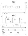
- the mirror / grating 11 is back and forth by the piezo drive 12 in such a way that the CO2 laser jumps back and forth on its lines R (16) and R (18) (FIG. 7), ie between the two wavelengths ⁇ 1 and ⁇ 2 (see Fig. 2) jumps rectangularly.
- the piezo drive 12 is e.g. by adjusting an offset voltage so "detuned" that the output intensity (see FIG. 2, left axis) is essentially of the same order of magnitude for both wavelengths.
- the chopper 30 interrupts the laser beam 1 synchronized to switch its wavelengths, so that the intensity pattern shown in FIG. 3 arises over time, the area A being a laser beam with the wavelength ⁇ 1, the area B being a beam with the wavelength ⁇ 2 and the area C represents an area in which the laser beam 1 is interrupted by the chopper 30. Signals then emerge at the outputs of the detectors 35 and 36, the time profile of which corresponds to that according to FIG. 3, the average DC value of the detector output signals being zero.
- the output signals of the detectors 35 and 36 are sampled via sample + hold circuits, as shown in FIG. 4, so that after a complete Cycle AC a total of six values are stored.
- AI, BI, CI output values AC of detector 35
- AII, BII, CII output values of detector 36.
- the processed signals A are thus obtained at the wavelength ⁇ 1 (absorption maximum of NH3), the values B at the wavelength ⁇ 2 (absorption minimum), while the values C represent the optical zero point.
- the concentration K of the gas under investigation can be derived directly from this.
- the evaluation unit 40 Since the absorption is only linearly dependent in some areas on the pressure and temperature of the gas in the measuring section, the evaluation unit 40 has stored correction tables which contain correction values according to FIGS. 8 and 9, which are then selected in accordance with the output signals of the sensors 37, 38 and for correction of the measurement results are used.
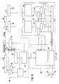
- the piezo controller 50 for controlling the piezo drive 12 of the laser emitter unit 10 comprises a frequency generator 51 which determines the cycle for switching the wavelength back and forth and for interrupting the laser output beam 1.
- the frequency generator 51 is therefore connected on the output side, on the one hand, to the chopper control 31 and, on the other hand, to a modulator 52, the output signal of which is connected to one input of a Summing amplifier / driver 54 is guided, on the other input of which there is an offset circuit 53 with its output.
- This offset circuit 53 is controlled by the stabilization 34.
- a clock signal from the frequency generator 51 is also connected to a corresponding input of a clock control 48 of the evaluation unit 40.
- the clock controller 48 sends clock signals A, B and C to sample + hold circuits 43 and 44, which are connected to outputs of analog processing circuits 41 and 42, which preprocess the output signals of the pyroelectric detectors 35 and 36.
- This preprocessing consists in particular in decoupling the offset voltage, filtering out (HF) interference and amplifying the signals.
- the detector values A, B and C stored in the sample + hold circuits 43 and 44 are digitized via an A / D converter 45 and together with a clock signal or trigger (from the frequency generator 51) of a computer circuit 46 (for example a minicomputer) fed. Furthermore, the computer circuit 46 (digitized) output signals of the sensors 37 and 38 for temperature and pressure in the measuring section are supplied. In the computer circuit 46, the signals stored in the sample + hold circuits 43 and 44 are calculated in each cycle in accordance with the above-mentioned regulation, possibly stored and output via an output port 47.
- the mirrors 21 and 22 already explained with reference to FIG. 1 are designed as concave mirrors, each of which is seated in a housing 28 via adjusting devices 27.
- the housing 28 of the two mirrors 21 and 22 are in opposite walls of a fireplace 39 mon animals, so that with a suitable setting of the mirror via the adjusting elements 27, a laser beam 1, which is directed through a hole 23 in the mirror 21 onto the opposite mirror 22, is reflected by the latter back onto the mirror 21 and is thus mirrored back and forth several times until it finally emerges again as a measuring beam m through the hole 23 in the mirror 21.
- the mirrors 21 and 22 are preferably arranged adjustable at a distance d from one another which corresponds to twice the focal length f of the mirrors.
- purge air channels 29 are provided, through which purge gas is introduced into the chimney (in the direction of the arrow) in such a way that the mirror surfaces are protected from contamination, e.g. are protected by solids in the flue gases.
- the measuring principle already described in detail above is used, but the laser output beam 1 is broken down via mirror arrangements 119, 119 'into a matrix-like arrangement of individual measuring beams, which after passing through the measuring sections 20 are each adjusted to groups of detectors 125, 125 ', the output signals of which are then fed back to an evaluation unit 40.
- the evaluation unit 40 forms a tomogram-like representation from the measured values, which can be output as expression 100 and then represents a two-dimensional concentration profile over the cross section of the chimney.
- the invention relates not only to a 13 CO2 laser, but generally on lasers whose wavelengths can be tuned to at least two values, i.e. also on laser diodes.
- each measured value can be derived from three individual values obtained in very short succession, which in turn means that turbulence in the flue gas or vibrations (building vibrations) at the installation site do not influence the measurement result, since the rates of change in pressure and Flow in the turbulence or the upper limit frequencies for building vibrations are lower than the measuring speed of the system.
- other gases can of course be detected in a corresponding manner using the method shown here or the system explained here.
- a CO2 laser has a very high power, so that particularly long measuring sections can be built and therefore high sensitivities can be achieved.
Landscapes
- Physics & Mathematics (AREA)
- Spectroscopy & Molecular Physics (AREA)
- Analytical Chemistry (AREA)
- Health & Medical Sciences (AREA)
- Life Sciences & Earth Sciences (AREA)
- Chemical & Material Sciences (AREA)
- Optics & Photonics (AREA)
- Biochemistry (AREA)
- General Health & Medical Sciences (AREA)
- General Physics & Mathematics (AREA)
- Immunology (AREA)
- Pathology (AREA)
- Investigating Or Analysing Materials By Optical Means (AREA)
- Sampling And Sample Adjustment (AREA)
Applications Claiming Priority (2)
| Application Number | Priority Date | Filing Date | Title |
|---|---|---|---|
| DE19873741026 DE3741026A1 (de) | 1987-12-03 | 1987-12-03 | Verfahren und system zur (spuren-) gasanalyse |
| DE3741026 | 1987-12-03 |
Publications (3)
| Publication Number | Publication Date |
|---|---|
| EP0318752A2 true EP0318752A2 (fr) | 1989-06-07 |
| EP0318752A3 EP0318752A3 (en) | 1990-07-18 |
| EP0318752B1 EP0318752B1 (fr) | 1995-06-07 |
Family
ID=6341831
Family Applications (1)
| Application Number | Title | Priority Date | Filing Date |
|---|---|---|---|
| EP88118969A Expired - Lifetime EP0318752B1 (fr) | 1987-12-03 | 1988-11-14 | Système pour l'analyse de traces de gaz |
Country Status (6)
| Country | Link |
|---|---|
| US (1) | US5002391A (fr) |
| EP (1) | EP0318752B1 (fr) |
| JP (1) | JP2603119B2 (fr) |
| AT (1) | ATE123570T1 (fr) |
| CA (1) | CA1327128C (fr) |
| DE (2) | DE3741026A1 (fr) |
Cited By (9)
| Publication number | Priority date | Publication date | Assignee | Title |
|---|---|---|---|---|
| WO1992004614A1 (fr) * | 1990-09-07 | 1992-03-19 | Chlean Plants & Engineering Establishment | Procede pour la determination de la concentration de substances, dispositif pour la mise en ×uvre de ce procede, application dudit procede pour faire varier la concentration d'une substance contenue dans un fluide et appareillage y relatif |
| US5149983A (en) * | 1990-09-07 | 1992-09-22 | Chlean Plants & Engineering Establishment | Method and apparatus for measuring the concentration of at least one material in a fluid medium mixed materials |
| EP0657731A1 (fr) * | 1993-12-10 | 1995-06-14 | Karl Stefan Riener | Procédé et appareil pour déterminer une absorption caractéristique d'une substance |
| US5585636A (en) * | 1993-12-10 | 1996-12-17 | Karl Stefan Reiner | Characteristic absorption |
| EP0921390A1 (fr) * | 1997-12-05 | 1999-06-09 | Oldham France S.A. | Procédé de détermination de la concentration d'un gaz dans un mélange gazeux et dispositif d'analyse pour la mise en oeuvre d'un tel procédé |
| RU2227286C1 (ru) * | 2002-10-18 | 2004-04-20 | Московский инженерно-физический институт (государственный университет) | Способ определения концентрации йодосодержащих веществ, образующихся при переработке отработанного ядерного топлива, и устройство для его осуществления |
| EP2416145A1 (fr) * | 2010-08-04 | 2012-02-08 | SICK MAIHAK GmbH | Dispositif destiné à l'analyse d'un fluide |
| EP2428793A1 (fr) * | 2010-09-08 | 2012-03-14 | SICK MAIHAK GmbH | Dispositif de rinçage de gaz d'une surface limite optique et dispositif d'analyse optique |
| EP2679982A1 (fr) * | 2012-06-28 | 2014-01-01 | ELMOS Semiconductor AG | Système de capteur et procédé destinés à la mesure des propriétés de transmission d'une voie de transmission d'un système de mesure entre un émetteur et un récepteur |
Families Citing this family (45)
| Publication number | Priority date | Publication date | Assignee | Title |
|---|---|---|---|---|
| US5200629A (en) * | 1990-10-12 | 1993-04-06 | Chlean Plants & Engineering Establishment | Method and system for changing the concentration of one material in a fluid medium of mixed materials |
| JPH04148846A (ja) * | 1990-10-13 | 1992-05-21 | Jasco Corp | 濃度補正装置 |
| US5210702A (en) * | 1990-12-26 | 1993-05-11 | Colorado Seminary | Apparatus for remote analysis of vehicle emissions |
| US5489777A (en) * | 1990-12-26 | 1996-02-06 | Denver Seminary | Apparatus for remote analysis of vehicle emissions using reflective thermography |
| US5401967A (en) * | 1990-12-26 | 1995-03-28 | Colorado Seminary Dba University Of Denver | Apparatus for remote analysis of vehicle emissions |
| US5179422A (en) * | 1991-05-15 | 1993-01-12 | Environmental Research Institute Of Michigan | Contamination detection system |
| JPH0560687A (ja) * | 1991-09-05 | 1993-03-12 | Matsushita Electric Ind Co Ltd | 赤外分析装置 |
| US5252060A (en) * | 1992-03-27 | 1993-10-12 | Mckinnon J Thomas | Infrared laser fault detection method for hazardous waste incineration |
| US5291265A (en) * | 1992-06-03 | 1994-03-01 | Aerodyne Research, Inc. | Off-axis cavity absorption cell |
| DE4300853C2 (de) * | 1993-01-15 | 2003-09-04 | Daimler Chrysler Ag | Verfahren zur spektroskopischen Bestimmung des Stickstoffoxidgehalts |
| DE4338233C2 (de) * | 1993-11-09 | 1997-02-06 | Fraunhofer Ges Forschung | Verfahren und Anordnung zur abwechselnden Proben- und Untergrundmessung, insbesondere bei der hochempfindlichen absorptionsspektroskopischen, selektiven Spurengasanalyse |
| DE4402054A1 (de) * | 1994-01-25 | 1995-07-27 | Zeiss Carl Fa | Gaslaser und Gasnachweis damit |
| DE4422400C2 (de) * | 1994-06-27 | 1996-06-27 | Abb Management Ag | Verfahren zur Bestimmung des Anteils eines 1. chemischen Stoffes in einem 2. chemischen Stoff oder Stoffgemisch |
| DE4446390C1 (de) * | 1994-12-23 | 1996-07-04 | Siemens Ag | Verfahren und Vorrichtung zur Messung der Konzentration eines in einer Probe enthaltenen Analyten |
| DE19525415C2 (de) * | 1995-07-12 | 1997-11-27 | Optikzentrum Nrw Gmbh Oz | Verfahren und Vorrichtung zur Bestimmung der Wasserdampfkonzentration bzw. des Taupunktes |
| DE19528960C2 (de) * | 1995-08-08 | 1997-07-17 | Eltro Gmbh | Verfahren und Einrichtung zur Fernmessung von Luftschadstoffen |
| DE19611290C2 (de) * | 1996-03-22 | 1998-04-16 | Draegerwerk Ag | Gassensor |
| US5831267A (en) * | 1997-02-24 | 1998-11-03 | Envirotest Systems Corp. | Method and apparatus for remote measurement of exhaust gas |
| DE19840794C1 (de) * | 1998-09-08 | 2000-03-23 | Deutsch Zentr Luft & Raumfahrt | Verfahren und Vorrichtung zur Erfassung von Infrarot-Strahlungseigenschaften von Abgasen |
| US6154307A (en) | 1998-09-18 | 2000-11-28 | United Technologies Corporation | Method and apparatus to diffract multiple beams |
| US6089076A (en) * | 1998-09-18 | 2000-07-18 | United Technologies Corporation | System to control the power of a beam |
| DE19902396C2 (de) * | 1999-01-22 | 2002-06-27 | Conducta Endress & Hauser | Anordnung zum Messen des Nitratgehalts von Flüssigkeiten |
| US6261851B1 (en) | 1999-09-30 | 2001-07-17 | International Business Machines Corporation | Optimization of CMP process by detecting of oxide/nitride interface using IR system |
| US6561027B2 (en) | 2000-12-29 | 2003-05-13 | Spx Corporation | Support structure for system for measuring vehicle speed and/or acceleration |
| US6781110B2 (en) * | 2000-12-29 | 2004-08-24 | Spx Corporation | Apparatus and method for measuring vehicle speed and/or acceleration |
| US6750444B2 (en) | 2000-12-29 | 2004-06-15 | Spx Corporation | Apparatus and method for measuring vehicle speed and/or acceleration |
| US6745613B2 (en) | 2001-08-13 | 2004-06-08 | Spx Corporation | Method and system for determining the type of fuel used to power a vehicle |
| US6857262B2 (en) | 2001-08-16 | 2005-02-22 | Spx Corporation | Catalytic converter function detection |
| US7183945B2 (en) * | 2001-08-17 | 2007-02-27 | Spx Corporation | Method and system for video capture of vehicle information |
| US20030034889A1 (en) | 2001-08-20 | 2003-02-20 | Rendahl Craig S. | Host system and method for sensed vehicle data |
| US6744516B2 (en) * | 2001-08-21 | 2004-06-01 | Spx Corporation | Optical path structure for open path emissions sensing |
| US6757607B2 (en) | 2001-08-23 | 2004-06-29 | Spx Corporation | Audit vehicle and audit method for remote emissions sensing |
| EP1291642A1 (fr) * | 2001-09-05 | 2003-03-12 | Linde Medical Sensors AG | Système de capteur pour la détection de substances chimiques comprenant un guide intégré d'ondes lumineuses |
| AT411298B (de) * | 2001-09-18 | 2003-11-25 | Gerhard Mag Totschnig | Verfahren zur laser-absorptionsspektroskopie und einrichtungen zur durchführung dieses verfahrens |
| EP1723407B1 (fr) * | 2004-03-09 | 2007-11-14 | Senscient Limited | Detection de gaz |
| US8255169B2 (en) | 2007-05-24 | 2012-08-28 | Zolo Technologies, Inc. | Binning and tomography for high spatial resolution temperature and species concentration measurements |
| JP5161012B2 (ja) * | 2008-09-12 | 2013-03-13 | 矢崎総業株式会社 | 濃度測定装置 |
| JP2009150909A (ja) * | 2009-04-02 | 2009-07-09 | Mitsubishi Heavy Ind Ltd | ガス濃度フラックス計測装置 |
| US8896835B2 (en) * | 2011-12-27 | 2014-11-25 | Horiba, Ltd. | Gas measurement apparatus and the setting method of width of wavelength modulation in gas measurement apparatus |
| JP5931557B2 (ja) * | 2012-04-13 | 2016-06-08 | 三菱重工業株式会社 | 濃度分布測定装置及び濃度分布測定方法 |
| FI125907B (en) * | 2013-09-24 | 2016-03-31 | Vaisala Oyj | Method and apparatus for measuring the concentration of gases dissolved in liquids |
| CN104979742B (zh) * | 2014-04-11 | 2018-01-16 | 中国科学院大连化学物理研究所 | 氧碘化学激光器光学谐振腔调节与监控系统及方法 |
| JP6857484B2 (ja) * | 2016-10-27 | 2021-04-14 | 日本光電工業株式会社 | 医用フォトメータ、および医用フォトメータの制御方法 |
| JP6794219B2 (ja) * | 2016-10-27 | 2020-12-02 | 日本光電工業株式会社 | 医用フォトメータ、および医用フォトメータの制御方法 |
| US10168276B1 (en) | 2017-11-08 | 2019-01-01 | Itron, Inc. | Identifying targeted gaseous chemical compound |
Family Cites Families (11)
| Publication number | Priority date | Publication date | Assignee | Title |
|---|---|---|---|---|
| DE1964469C3 (de) * | 1969-12-23 | 1974-05-02 | Fa. Carl Zeiss, 7920 Heidenheim | Vorrichtung zur Atomabsorptionsanalyse einer Probe |
| DE2133080C3 (de) * | 1971-07-02 | 1974-10-17 | Siemens Ag, 1000 Berlin Und 8000 Muenchen | System zur optischen Kontrolle von Luftverunreinigungen in einem Großraum |
| FR2257900B1 (fr) * | 1973-09-20 | 1976-05-14 | France Etat | |
| CH569972A5 (fr) * | 1974-07-16 | 1975-11-28 | Cerberus Ag | |
| JPS6019910B2 (ja) * | 1979-10-11 | 1985-05-18 | 大塚製薬株式会社 | ベンゾ〔ij〕キノリジン−2−カルボン酸誘導体及びその製造法 |
| US4291988A (en) * | 1978-05-22 | 1981-09-29 | The United States Of America As Represented By The Secretary Of The Army | Automated path differencing system |
| US4386854A (en) * | 1980-02-27 | 1983-06-07 | The Board Of Trustees Of The Leland Stanford Junior University | Method and means for optically generating signals for use in monitoring an environment using tomographic techniques |
| US4425648A (en) * | 1980-12-29 | 1984-01-10 | Rockwell International Corporation | Wavelength selectivity of lasers and control thereof for rapid action measuring tasks |
| US4471220A (en) * | 1981-12-21 | 1984-09-11 | Exxon Research And Engineering Co. | System for monitoring trace gaseous ammonia concentration in flue gases |
| GB2127537B (en) * | 1982-09-09 | 1986-09-10 | Laser Applic Limited | Gas detection apparatus |
| DE3508707A1 (de) * | 1985-03-12 | 1986-09-18 | Battelle-Institut E.V., 6000 Frankfurt | Anordnung zur schnellen umschaltung zwischen verschiedenen wellenlaengen bei lasern |
-
1987
- 1987-12-03 DE DE19873741026 patent/DE3741026A1/de not_active Ceased
-
1988
- 1988-11-14 AT AT88118969T patent/ATE123570T1/de not_active IP Right Cessation
- 1988-11-14 DE DE3853941T patent/DE3853941D1/de not_active Expired - Fee Related
- 1988-11-14 EP EP88118969A patent/EP0318752B1/fr not_active Expired - Lifetime
- 1988-12-01 CA CA000584769A patent/CA1327128C/fr not_active Expired - Fee Related
- 1988-12-02 US US07/279,214 patent/US5002391A/en not_active Expired - Fee Related
- 1988-12-02 JP JP63304334A patent/JP2603119B2/ja not_active Expired - Lifetime
Cited By (12)
| Publication number | Priority date | Publication date | Assignee | Title |
|---|---|---|---|---|
| WO1992004614A1 (fr) * | 1990-09-07 | 1992-03-19 | Chlean Plants & Engineering Establishment | Procede pour la determination de la concentration de substances, dispositif pour la mise en ×uvre de ce procede, application dudit procede pour faire varier la concentration d'une substance contenue dans un fluide et appareillage y relatif |
| US5149983A (en) * | 1990-09-07 | 1992-09-22 | Chlean Plants & Engineering Establishment | Method and apparatus for measuring the concentration of at least one material in a fluid medium mixed materials |
| EP0657731A1 (fr) * | 1993-12-10 | 1995-06-14 | Karl Stefan Riener | Procédé et appareil pour déterminer une absorption caractéristique d'une substance |
| US5585636A (en) * | 1993-12-10 | 1996-12-17 | Karl Stefan Reiner | Characteristic absorption |
| EP0921390A1 (fr) * | 1997-12-05 | 1999-06-09 | Oldham France S.A. | Procédé de détermination de la concentration d'un gaz dans un mélange gazeux et dispositif d'analyse pour la mise en oeuvre d'un tel procédé |
| FR2772127A1 (fr) * | 1997-12-05 | 1999-06-11 | Oldham France Sa | Procede de determination de la concentration d'un gaz dans un melange gazeux et dispositif d'analyse pour la mise en oeuvre d'un tel procede |
| US6218666B1 (en) | 1997-12-05 | 2001-04-17 | Oldham France S.A. | Method of determining the concentration of a gas in a gas mixture and analyzer for implementing such a method |
| RU2227286C1 (ru) * | 2002-10-18 | 2004-04-20 | Московский инженерно-физический институт (государственный университет) | Способ определения концентрации йодосодержащих веществ, образующихся при переработке отработанного ядерного топлива, и устройство для его осуществления |
| EP2416145A1 (fr) * | 2010-08-04 | 2012-02-08 | SICK MAIHAK GmbH | Dispositif destiné à l'analyse d'un fluide |
| US8531653B2 (en) | 2010-08-04 | 2013-09-10 | Sick Ag | Apparatus for the analysis of a fluid |
| EP2428793A1 (fr) * | 2010-09-08 | 2012-03-14 | SICK MAIHAK GmbH | Dispositif de rinçage de gaz d'une surface limite optique et dispositif d'analyse optique |
| EP2679982A1 (fr) * | 2012-06-28 | 2014-01-01 | ELMOS Semiconductor AG | Système de capteur et procédé destinés à la mesure des propriétés de transmission d'une voie de transmission d'un système de mesure entre un émetteur et un récepteur |
Also Published As
| Publication number | Publication date |
|---|---|
| CA1327128C (fr) | 1994-02-22 |
| ATE123570T1 (de) | 1995-06-15 |
| JP2603119B2 (ja) | 1997-04-23 |
| EP0318752B1 (fr) | 1995-06-07 |
| DE3853941D1 (de) | 1995-07-13 |
| US5002391A (en) | 1991-03-26 |
| JPH01301149A (ja) | 1989-12-05 |
| EP0318752A3 (en) | 1990-07-18 |
| DE3741026A1 (de) | 1989-06-15 |
Similar Documents
| Publication | Publication Date | Title |
|---|---|---|
| EP0318752A2 (fr) | Système pour l'analyse de traces de gaz | |
| EP1183520B1 (fr) | Dispositif de capteur de gaz | |
| EP0587609B1 (fr) | Procede et dispositif pour la spectroscopie d'emission | |
| DE2365605C3 (de) | Spektralphotometer | |
| DE3852176T2 (de) | Verfahren zur steuerung einer strahlungsquelle und einer regelbaren strahlungsquelle. | |
| DE3852108T2 (de) | Vorrichtung und verfahren zur optischen messung der konzentration an material. | |
| DE2202969A1 (de) | Vorrichtung fuer die Fernanalyse von Gasen | |
| DE69222425T2 (de) | Methode und apparat zur multivariablen charakterisation der antwort eines optischen instruments | |
| DE2438294A1 (de) | Verfahren zur messung kleiner gaskonzentrationen | |
| DE3006421A1 (de) | Analysegeraet zum kennzeichnen eines besonderen bestandteils in einer probe | |
| DE102005028268A1 (de) | Verfahren und Vorrichtung zur Erzeugung und Detektion eines Raman-Spektrums | |
| DE69315015T2 (de) | Spektrophotometrische Methode und Spektrophotometer zur Druchführung der Methode | |
| EP0174496A2 (fr) | Méthode pour déterminer la longueur d'onde et la puissance de rayonnement de sources de lumière monochromatique avec correction de l'influence de la longueur d'onde et dispositif pour réaliser ce procédé | |
| EP0145877A2 (fr) | Photomètre pour l'analyse en continu d'un milieu (gaz ou liquide) | |
| DE4122572A1 (de) | Verfahren zum betrieb einer laserdiode | |
| DE69009475T2 (de) | Farbsteuerung. | |
| DE102016108267B4 (de) | Vorrichtung und Verfahren zum Ermitteln einer Konzentration von wenigstens einer Gaskomponente eines Gasgemischs | |
| DE102004025448B4 (de) | Verfahren zum Messen eines Spektrums einer Messprobe mittels eines Infrarot-Spektrometers und derartiges Infrarot-Spektrometer | |
| DE3541165C2 (fr) | ||
| DE69735565T2 (de) | Optisches Messgerät mit wellenlängenselektiver Lichtquelle | |
| DE2130331A1 (de) | Verfahren und Vorrichtung zur Konzentrationsbestimmung von Gasen durch optische Extinktionsmessung | |
| DE102004031643A1 (de) | Nichtdispersiver Infrarot-Gasanalysator | |
| DE19740210B4 (de) | Atomabsorptionsspektrometer | |
| DE19528960C2 (de) | Verfahren und Einrichtung zur Fernmessung von Luftschadstoffen | |
| DE3116344C2 (fr) |
Legal Events
| Date | Code | Title | Description |
|---|---|---|---|
| PUAI | Public reference made under article 153(3) epc to a published international application that has entered the european phase |
Free format text: ORIGINAL CODE: 0009012 |
|
| AK | Designated contracting states |
Kind code of ref document: A2 Designated state(s): AT BE CH DE ES FR GB GR IT LI NL SE |
|
| PUAL | Search report despatched |
Free format text: ORIGINAL CODE: 0009013 |
|
| AK | Designated contracting states |
Kind code of ref document: A3 Designated state(s): AT BE CH DE ES FR GB GR IT LI NL SE |
|
| 17P | Request for examination filed |
Effective date: 19900829 |
|
| 17Q | First examination report despatched |
Effective date: 19911205 |
|
| RAP1 | Party data changed (applicant data changed or rights of an application transferred) |
Owner name: TECHFORM ENGINEERING AG |
|
| GRAA | (expected) grant |
Free format text: ORIGINAL CODE: 0009210 |
|
| AK | Designated contracting states |
Kind code of ref document: B1 Designated state(s): AT BE CH DE ES FR GB GR IT LI NL SE |
|
| PG25 | Lapsed in a contracting state [announced via postgrant information from national office to epo] |
Ref country code: IT Free format text: LAPSE BECAUSE OF FAILURE TO SUBMIT A TRANSLATION OF THE DESCRIPTION OR TO PAY THE FEE WITHIN THE PRE;WARNING: LAPSES OF ITALIAN PATENTS WITH EFFECTIVE DATE BEFORE 2007 MAY HAVE OCCURRED AT ANY TIME BEFORE 2007. THE CORRECT EFFECTIVE DATE MAY BE DIFFERENT FROM THE ONE RECORDED.SCRIBED TIME-LIMIT Effective date: 19950607 Ref country code: ES Free format text: THE PATENT HAS BEEN ANNULLED BY A DECISION OF A NATIONAL AUTHORITY Effective date: 19950607 Ref country code: GR Free format text: LAPSE BECAUSE OF FAILURE TO SUBMIT A TRANSLATION OF THE DESCRIPTION OR TO PAY THE FEE WITHIN THE PRESCRIBED TIME-LIMIT Effective date: 19950607 |
|
| REF | Corresponds to: |
Ref document number: 123570 Country of ref document: AT Date of ref document: 19950615 Kind code of ref document: T |
|
| ET | Fr: translation filed | ||
| GBT | Gb: translation of ep patent filed (gb section 77(6)(a)/1977) |
Effective date: 19950605 |
|
| REF | Corresponds to: |
Ref document number: 3853941 Country of ref document: DE Date of ref document: 19950713 |
|
| PLBE | No opposition filed within time limit |
Free format text: ORIGINAL CODE: 0009261 |
|
| STAA | Information on the status of an ep patent application or granted ep patent |
Free format text: STATUS: NO OPPOSITION FILED WITHIN TIME LIMIT |
|
| 26N | No opposition filed | ||
| PGFP | Annual fee paid to national office [announced via postgrant information from national office to epo] |
Ref country code: GB Payment date: 19981229 Year of fee payment: 11 |
|
| PGFP | Annual fee paid to national office [announced via postgrant information from national office to epo] |
Ref country code: DE Payment date: 19990129 Year of fee payment: 11 |
|
| NLS | Nl: assignments of ep-patents |
Owner name: TECHFORM TECHNOLOGY AG |
|
| REG | Reference to a national code |
Ref country code: FR Ref legal event code: TP |
|
| PG25 | Lapsed in a contracting state [announced via postgrant information from national office to epo] |
Ref country code: GB Free format text: LAPSE BECAUSE OF NON-PAYMENT OF DUE FEES Effective date: 19991114 |
|
| GBPC | Gb: european patent ceased through non-payment of renewal fee |
Effective date: 19991114 |
|
| PG25 | Lapsed in a contracting state [announced via postgrant information from national office to epo] |
Ref country code: DE Free format text: LAPSE BECAUSE OF NON-PAYMENT OF DUE FEES Effective date: 20000901 |
|
| PGFP | Annual fee paid to national office [announced via postgrant information from national office to epo] |
Ref country code: AT Payment date: 20001130 Year of fee payment: 13 Ref country code: FR Payment date: 20001130 Year of fee payment: 13 Ref country code: NL Payment date: 20001130 Year of fee payment: 13 Ref country code: SE Payment date: 20001130 Year of fee payment: 13 |
|
| PGFP | Annual fee paid to national office [announced via postgrant information from national office to epo] |
Ref country code: BE Payment date: 20001219 Year of fee payment: 13 |
|
| PGFP | Annual fee paid to national office [announced via postgrant information from national office to epo] |
Ref country code: CH Payment date: 20010208 Year of fee payment: 13 |
|
| PG25 | Lapsed in a contracting state [announced via postgrant information from national office to epo] |
Ref country code: AT Free format text: LAPSE BECAUSE OF NON-PAYMENT OF DUE FEES Effective date: 20011114 |
|
| PG25 | Lapsed in a contracting state [announced via postgrant information from national office to epo] |
Ref country code: SE Free format text: LAPSE BECAUSE OF NON-PAYMENT OF DUE FEES Effective date: 20011115 |
|
| PG25 | Lapsed in a contracting state [announced via postgrant information from national office to epo] |
Ref country code: BE Free format text: LAPSE BECAUSE OF NON-PAYMENT OF DUE FEES Effective date: 20011130 Ref country code: LI Free format text: LAPSE BECAUSE OF NON-PAYMENT OF DUE FEES Effective date: 20011130 Ref country code: CH Free format text: LAPSE BECAUSE OF NON-PAYMENT OF DUE FEES Effective date: 20011130 |
|
| BERE | Be: lapsed |
Owner name: TECHFORM TECHNOLOGY A.G. Effective date: 20011130 |
|
| PG25 | Lapsed in a contracting state [announced via postgrant information from national office to epo] |
Ref country code: NL Free format text: LAPSE BECAUSE OF NON-PAYMENT OF DUE FEES Effective date: 20020601 |
|
| EUG | Se: european patent has lapsed |
Ref document number: 88118969.0 |
|
| REG | Reference to a national code |
Ref country code: CH Ref legal event code: PL |
|
| PG25 | Lapsed in a contracting state [announced via postgrant information from national office to epo] |
Ref country code: FR Free format text: LAPSE BECAUSE OF NON-PAYMENT OF DUE FEES Effective date: 20020730 |
|
| NLV4 | Nl: lapsed or anulled due to non-payment of the annual fee |
Effective date: 20020601 |
|
| REG | Reference to a national code |
Ref country code: FR Ref legal event code: ST |
|
| REG | Reference to a national code |
Ref country code: FR Ref legal event code: ST |