EP0308397B1 - Rückentraggestell - Google Patents
Rückentraggestell Download PDFInfo
- Publication number
- EP0308397B1 EP0308397B1 EP86902265A EP86902265A EP0308397B1 EP 0308397 B1 EP0308397 B1 EP 0308397B1 EP 86902265 A EP86902265 A EP 86902265A EP 86902265 A EP86902265 A EP 86902265A EP 0308397 B1 EP0308397 B1 EP 0308397B1
- Authority
- EP
- European Patent Office
- Prior art keywords
- load
- pack frame
- longitudinal beams
- carrier
- slide plate
- Prior art date
- Legal status (The legal status is an assumption and is not a legal conclusion. Google has not performed a legal analysis and makes no representation as to the accuracy of the status listed.)
- Expired - Lifetime
Links
- 230000008878 coupling Effects 0.000 claims abstract description 50
- 238000010168 coupling process Methods 0.000 claims abstract description 50
- 238000005859 coupling reaction Methods 0.000 claims abstract description 50
- 239000000463 material Substances 0.000 claims abstract description 8
- 238000003780 insertion Methods 0.000 claims description 16
- 230000037431 insertion Effects 0.000 claims description 16
- 239000004033 plastic Substances 0.000 claims description 7
- 229920003023 plastic Polymers 0.000 claims description 7
- 229920005830 Polyurethane Foam Polymers 0.000 claims description 3
- 239000003365 glass fiber Substances 0.000 claims description 3
- 230000002787 reinforcement Effects 0.000 claims description 3
- 230000000630 rising effect Effects 0.000 claims description 3
- 229920001187 thermosetting polymer Polymers 0.000 claims description 3
- 239000011496 polyurethane foam Substances 0.000 claims description 2
- 210000002105 tongue Anatomy 0.000 description 6
- 239000011324 bead Substances 0.000 description 4
- 239000010410 layer Substances 0.000 description 4
- 206010041662 Splinter Diseases 0.000 description 3
- 239000004744 fabric Substances 0.000 description 3
- 230000002349 favourable effect Effects 0.000 description 2
- 230000006872 improvement Effects 0.000 description 2
- TVEXGJYMHHTVKP-UHFFFAOYSA-N 6-oxabicyclo[3.2.1]oct-3-en-7-one Chemical compound C1C2C(=O)OC1C=CC2 TVEXGJYMHHTVKP-UHFFFAOYSA-N 0.000 description 1
- 230000015572 biosynthetic process Effects 0.000 description 1
- 238000010276 construction Methods 0.000 description 1
- 230000003292 diminished effect Effects 0.000 description 1
- 239000013013 elastic material Substances 0.000 description 1
- 238000005538 encapsulation Methods 0.000 description 1
- 238000009413 insulation Methods 0.000 description 1
- 230000001788 irregular Effects 0.000 description 1
- 239000002184 metal Substances 0.000 description 1
- 238000012856 packing Methods 0.000 description 1
- 230000000149 penetrating effect Effects 0.000 description 1
- 230000035515 penetration Effects 0.000 description 1
- 239000011241 protective layer Substances 0.000 description 1
- 230000005855 radiation Effects 0.000 description 1
- 230000003014 reinforcing effect Effects 0.000 description 1
- 230000000717 retained effect Effects 0.000 description 1
- 230000007480 spreading Effects 0.000 description 1
- 239000004753 textile Substances 0.000 description 1
Images


Classifications
-
- A—HUMAN NECESSITIES
- A45—HAND OR TRAVELLING ARTICLES
- A45F—TRAVELLING OR CAMP EQUIPMENT: SACKS OR PACKS CARRIED ON THE BODY
- A45F4/00—Travelling or camp articles which may be converted into other articles or into objects for other use; Sacks or packs carried on the body and convertible into other articles or into objects for other use
- A45F4/02—Sacks or packs convertible into other articles or into objects for other use
- A45F4/08—Sacks or packs convertible into other articles or into objects for other use into hammocks, litters or sleeping-bags
-
- A—HUMAN NECESSITIES
- A61—MEDICAL OR VETERINARY SCIENCE; HYGIENE
- A61G—TRANSPORT, PERSONAL CONVEYANCES, OR ACCOMMODATION SPECIALLY ADAPTED FOR PATIENTS OR DISABLED PERSONS; OPERATING TABLES OR CHAIRS; CHAIRS FOR DENTISTRY; FUNERAL DEVICES
- A61G1/00—Stretchers
- A61G1/007—Stretchers with skis or sled runners
-
- A—HUMAN NECESSITIES
- A61—MEDICAL OR VETERINARY SCIENCE; HYGIENE
- A61G—TRANSPORT, PERSONAL CONVEYANCES, OR ACCOMMODATION SPECIALLY ADAPTED FOR PATIENTS OR DISABLED PERSONS; OPERATING TABLES OR CHAIRS; CHAIRS FOR DENTISTRY; FUNERAL DEVICES
- A61G1/00—Stretchers
- A61G1/013—Stretchers foldable or collapsible
-
- A—HUMAN NECESSITIES
- A61—MEDICAL OR VETERINARY SCIENCE; HYGIENE
- A61G—TRANSPORT, PERSONAL CONVEYANCES, OR ACCOMMODATION SPECIALLY ADAPTED FOR PATIENTS OR DISABLED PERSONS; OPERATING TABLES OR CHAIRS; CHAIRS FOR DENTISTRY; FUNERAL DEVICES
- A61G1/00—Stretchers
- A61G1/04—Parts, details or accessories, e.g. head-, foot-, or like rests specially adapted for stretchers
- A61G1/044—Straps, bands or belts
Definitions
- the invention relates to a backpack frame according to the preamble of claim 1.
- Such a back frame can be found in FR-A-2520610.
- the longitudinal spars on the load-bearing side are covered with a tarpaulin through which straps are threaded.
- the ends of the sled are used to fasten the injured person, with the load-side longitudinal bars serving as runners.
- Transverse pipe sections that connect the longitudinal spars on each side serve as coupling parts, which are pushed into one another and connected by a screw.
- a backpack can be strapped in the space enclosed by the longitudinal spars without support.
- US-A-3, 897, 894 describes an upper end bracket for a packing frame, the bent ends of which the side legs can be inserted into the two open longitudinal spars, in which they are fixed by split pins.
- the bracket can be cantilevered on the carrier side or load side and is used to attach weather protection or to better distribute the load to be transported.
- FR-A-2.108.434 shows a transport stretcher that can be assembled from two parts or consists of two hinged parts, each part in turn having four longitudinal spars.
- a support for the injured person is tensioned between the upper pair, and a protective layer for the injured person, which also improves the sliding property, can additionally be provided between the lower pair.
- Backpacks are not used for load transport.
- the invention has now set itself the task of creating a back frame that not only allows extended uses by combining two back frames, but is more suitable both for use as a backpack frame and after doubling for any purpose.
- these improvements should relate to the attachment of the loads to be transported to the back frame and the transport properties, so that the device is more like a backpack, stretcher and sledge.
- a back support frame is thus available, in which the spatial arrangement of the four longitudinal spars forms a cavity that takes up the usual riser straps and fastening, but not the load.
- the width of the narrow sides is small, so that a high level of comfort is achieved.
- the load-handling area is outside the gliding plane during back transport and has a variable volume.
- the brackets are fixed on the narrow sides, that is to say laterally, since the holding elements can be designed there in any desired manner.
- a plurality of holding elements can also be provided one above the other, which results in a height adjustment of the bracket and also the possibility of providing two or more brackets one above the other.
- the sliding plane required for use as a slide is not interrupted, so that the slide has very good sliding properties.
- the simple back frame can be used as a small single sled, and two mirrored back frames can be used as a larger transport or rescue sled.
- the load can now be fixed on the load side when used as a backpack, the load or the person to be transported can be fixed on the carrier side when used as a sled or stretcher, with a volume of the receiving space that is variable outside the main part cavity formed by the longitudinal spars.
- an encapsulation sheet made of flexible material and divided into several side wall parts can be attached to each longitudinal spar on the support side for load fastening.
- each pair of side wall parts can thus not only be adapted to the load or person size given at this point, but in the case of loads with a particularly unfavorable shape it is also possible, if appropriate, to connect staggered opposite side wall parts to one another.
- the spatial longitudinal beam arrangement with holding elements on the narrow sides also allows a preferred embodiment in which a sliding plate is arranged between the load-side longitudinal beams, which further facilitates use as a slide, especially in rough terrain.
- the slide plate is preferably made of an elastically bendable plastic, so that the load-side longitudinal spars form reinforcing edge runners, as a result of which longitudinal guidance is also achieved in sloping terrain.
- the sliding plate on the coupling-side narrow side has an obliquely raised edge struts freely protruding between two cross bars and is fixed on the opposite narrow side on the cross bar.
- the joint is thus raised in a wave-like manner and is formed at the point of greatest ground clearance at which it has the least influence on the sliding properties.
- the slide plate can also be designed to be bullet and splinter-resistant, for example by means of fabric inserts such as are used for military helmets.
- a slide plate made of plastic can also be so thick that the load-side longitudinal bars are embedded in their edge areas as reinforcements. Since the sliding plate should have high strength and low weight, it can be constructed, for example, in multiple layers, the two outer layers consisting of a glass fiber reinforced thermosetting material hardenable by UV radiation and an inner layer consisting of PU foam. In this embodiment too, the sliding plate can be made bullet and splinter-resistant by means of fabric inserts.
- Each holding element is preferably formed in the region of a crossbar, which connects the longitudinal spar on the support side and the longitudinal spar on the narrow side on the load side.
- each holding element is formed by a hollow cross member, which connects the two longitudinal members, and has a load-side insertion opening, the cross member on the load side is rising, and that each end piece of the bracket forms an insertion pin in a holding element.
- the angle of the rising crossbars is preferably 10 ° to the horizontal.
- the bracket can be removed and used as a pull bracket.
- ski sticks can be connected to the bracket or to the support frame, for example, by means of straps or belts.
- a plug connection for the pull bracket can be achieved if the upper end sections of the load-side longitudinal bars have insertion openings and the end sections, the cross bars and the insertion pins of the bracket lie in the same spatial arrangement with respect to one another, for example, diverge slightly.
- the two longitudinal beams on the carrier side each have at least one latching support as holding elements for the bracket projecting over the longitudinal beams on the load side, into which it can be suspended.
- Each latching support can, however, also be formed by a bead of the carrier-side longitudinal spar extending on the load side, the beaded region being supported on the adjacent load-side longitudinal spar via the cross member.
- a particularly suitable bracket is angled at an angle and provided with U-shaped end hooks. For use as a sled this version of the bracket can be attached to the front ends of the side rails.
- the side wall parts which are made of flexible, in particular textile material, can be overlapped, for example, to form the covering and with conventional connecting elements, such as straps, bands or belts and buckles or the like. Mistake.
- the circumferential length of the wrapping can be adapted to a considerable extent to that of the loads to be transported if at least one of each pair of opposing side wall parts has a fold-out extension part and the free edge strip of the extension part and a connecting area overlapping the longitudinal strip form overlapping connecting areas, in which connecting elements are provided.
- Velcro strips are particularly suitable as connecting elements.
- the wrapping length of the side wall parts is preferably dimensioned such that they overlap one another during the transport of the injured person for fixing them, so that they are at least partially double-walled. This is also a welcome thermal insulation.
- a preferred embodiment for the stringing together of two back support frames provides that the lower end sections of the two longitudinal spars of one narrow side end in a common coupling piece which is designed on one narrow side as a coupling sleeve and on the other as a plug-in part which can be inserted into the coupling sleeve, with a tensile connection of the Coupling pieces can be produced.
- the coupling pieces likewise only have a low sliding resistance if the end section of each load-side longitudinal bar ending in a coupling piece is cranked on the carrier side.
- the version in which the slide plate is made of elastic plastic provides that the exposed edge strip of the slide plate is longer than half the insertion length of the plug-in part.
- the two exposed edge strips which are at an angle to one another, bend further elastically during the establishment of the connection and are thereby pressed against one another, so that a usable seal of the joint is obtained, which is retained even if there is a slight loosening of the tensile connection during use entry.
- a preferred embodiment provides that the plug-in part has at least one resilient tongue extending in the direction of insertion, the free end of which forms a barb, and that the coupling sleeve has a crossbar on which the barb can be snapped into place, the barb of the plug-in part of the second open side of the coupling sleeve is accessible.
- the two resilient tongues can be spread out with a rod, a branch or the finger from the second open side of the coupling sleeve and thus the barbs can be lifted laterally from the crossbar.
- Another possibility for immediate locking consists, for example, in that at least one locking pin is resiliently mounted in the side wall of the plug-in part, the coupling sleeve having a corresponding passage hole for each locking pin.
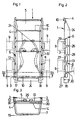
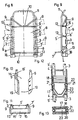
- FIG. 1-7 show a first embodiment of a back support frame according to the invention, namely FIG. 1 a top view on the support side and FIG. 2 a side view, FIG. 3 a section along the line III-III in FIG. 1 when used as a backpack, Fig. 4 two back racks assembled to a transport sled or a stretcher in longitudinal section, Fig. 5 shows a cross section in use as a slide and Fig. 6 and 7 details of a simplest design of the coupling in longitudinal and cross section, Figs. 8-13 8 shows a second embodiment of a back support frame according to the invention, namely FIG. 8 a top view, FIG. 9 a side view, FIG. 10 a detail in an enlarged oblique view, FIG.
- FIG. 11 a top view in use as a backpack and FIGS. 12 and 13 details of further coupling parts in the Longitudinal and cross-section
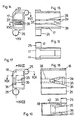
- Fig. 14 shows another embodiment of the plug part of the coupling in plan view of the plug-in end
- Fig. 15 and 16 sections after Line XV-XV and XVI-XVI of FIG. 14
- FIG. 17 shows a coupling sleeve of this embodiment in a top view of the second open side
- FIGS. 18 and 19 sections along the line XVIII-XVIII and XIX-XIX of FIG. 17.
- a back support frame 1 has four longitudinal bars 3, 4 in a spatial arrangement which is defined by the edges of a prism with a trapezoidal base (see FIG. 3, FIG. 12).
- Carrier-side longitudinal bars 3 are arranged at a greater distance from one another than load-side longitudinal bars 4.
- cross bars 13 are provided, and the load-side longitudinal bars 4 are interconnected by cross bars 10.
- the load-side longitudinal spars 4 form on the one hand edge skids (see FIG. 5) and / or edge reinforcements (see FIG. 10) of a sliding plate 5, 5 ', which is preferably made of plastic and in the middle part additionally not shown track ribs, center skids or the like. having.
- the front end portions of the load-side longitudinal beams 4 and the front part of the sliding plate 5, 5 ⁇ are angled towards the carrier side.
- the longitudinal bars 3, 4 end in coupling pieces 17, 18, with the aid of which, as can be seen in FIG. 4, two back support frames 1 can be assembled.
- the longitudinal beams 3 on the support side which are preferably formed by light metal round tubes, are provided with a plurality of holding elements 6 for brackets 7.
- Each holding element 6 consists of a hollow cross member 13 which is welded to the outside of the longitudinal side member 4, so that a bevelled insertion opening is provided on the load side (FIG. 3).
- FIG. 1 On the carrier side, thanks to the longitudinal bar arrangement, there is a niche or trough in which the carrying belts 31 (shoulder and waist belts) shown in dashed lines in FIG. 1 are arranged and tensioned in the usual manner for the back transport.
- a support network 29 or the like is between the longitudinal spars 3 on the support side.
- a bracket 7 can be inserted into the insertion openings of the hollow cross bars 13 (FIG. 3). It would also be conceivable to provide several brackets 7 one above the other in floors.
- Each bracket 7 has a U-shaped basic shape, the side legs are angled divergently and preferably form parallel insertion pins 30 at their ends, the length of which corresponds approximately to the length of a cross member 13.
- An additional connecting web 14 connects the side legs of the bracket.
- the bracket 7 with its two insertion pins 30 is inserted at the desired height into mutually opposite cross bars 13, the cross bar 14 coming into contact with the longitudinal bars 4 on the load side and thus the outside of the sliding plate 5.
- the middle part of each bracket 7 thus projects from the load side.
- a load can now (FIG. 2, 3) be placed on the cantilevered part of the bracket 7 which creates a floor.
- the side wall parts 9 FIG.
- FIGS. 1 and 2 are provided for the sake of clarity. These are made of flexible material, such as canvas or similar hard-wearing, weatherproof material, and are wrapped on one side to form a sleeve or loop or releasably fixed by means of ribbons and buckles.
- the connection 15 between the side wall parts 9 is also achieved, for example, by means of straps or bands and buckles.
- Each part of a longitudinal bar 3 on the support side connected to a holding element 6 can movably accommodate a side wall part 9, ie the section of the longitudinal bar 3 guided through the loop of the side wall part 9 serves as a pivot axis for the side wall part 9.
- the side wall parts 9 can be paired with both load and closed on the carrier side to form an envelope (FIGS. 3, 5).
- Four side wall parts 9 are preferably possible per longitudinal spar 3, two of which are shown in FIGS. 1 and 2.
- the slide plate 5 bent at the upper end of the support extends over the head of the support.
- the back support frame 1 can be used without changes as a slide, for example for the ground transport of a load.
- the side wall parts 9 serve to fasten the load, the same closure elements being used (FIG. 5).
- the sliding plate 5 forms a completely closed sliding surface, and due to the fixing of the brackets 7 on the narrow sides, no part protrudes outwards beyond the sliding plane.
- the removed bracket 7 can, as shown in Fig. 4, reinserted at the front end of the back frame 1 and the like by means of a band. be fixed where it serves as a drawbar or drawbar.
- the sliding plate 5 made of plastic that is bent up at the end provides a low sliding resistance on both sides. Since the middle area of the sliding plate 5 between the load-side longitudinal spars 4 is raised somewhat, these edge skids represent an improvement in directional stability.
- FIG. 4 For the formation of an enlarged transport sled, for example for the transport of the injured or for the training as a stretcher, two back support frames 1 are put together (FIG. 4).
- the coupling is composed of two coupling pieces that are inserted into each other (Fig. 6, 7).
- Each back support frame 1 has a coupling sleeve 18 on one side and a plug-in part 17 on the other side, which alternately interlock when assembled, since the two back support frames 1 are assembled in mirror image.
- both coupling pieces are approximately rectangular and have lateral receptacles 25, 26, into which the ends of both longitudinal spars 3, 4 are inserted. Since that too Plug part 17 is sleeve-like, a tensile connection 33 can extend through you coupling pieces.
- This tension-resistant connection 33 can be achieved by means of belts, bands or parts of the carrying belts 31 which are not otherwise required in the type of carriage use, but self-locking designs according to FIGS. 12, 13 or 14-19 are preferably used.
- a slide plate 5 made of flexible, elastic material is used, which is provided on the coupling side with a free-standing upright strip 24 between two cross bars 10, which protrudes into the end half of the coupling pieces.
- the carrier-side fixation of the "load” according to FIG. 5 is particularly important for the transport of the injured, since the injured person can be strapped in several times to the body by means of the side wall parts 9, and at the same time a warm covering is achieved.
- a pulling or holding bracket can be formed on both sides, in which the bracket 7 is inserted into the open, bent ends of the load-side longitudinal bars 4.
- a connection 32 can also be done here by means of straps, bands, belts or the like. achieve that enclose the end cross member 10 of the back support frame 1 and the connecting web 14 of the bracket 7.
- Ski poles can then be attached to the pulling or holding bracket, for example, so that an akja is created.
- the lying surface results from adjustable parts of the carrying belts 31 and from the mesh or grid insert 29 (FIGS. 3, 5) for the back transport.
- the sliding properties on snow are hardly diminished by the joint, as this is not in the gliding plane.
- the lying surface can also have continuous upholstery.
- the sliding plate 5 is also pulled up on the narrow side of the back support frame 1 and is preferably fixed on the longitudinal spars 3 on the support side.
- passage openings 28 are provided for the bracket 7 at the locations of the cross bars 13 and handle openings 27, so that you two stacked back support frames 1 are relatively easy to handle as a stretcher.
- Parts of the risers 31, which are also guided through the handle openings 27 and can be fixed to the longitudinal spars 3 on the support side, can also have eyelets, so that four such parts can be used to suspend a mountain rope hook of a helicopter.
- the sliding plate 5 ⁇ consists of a reinforced, preferably multi-layer plastic, and the load-side longitudinal bars 4 are embedded in the longitudinal edges of the sliding plate 5 ⁇ .
- the front part of the sliding plate 5 ⁇ is bent like a shovel towards the carrier side.
- the rear or lower end sections of the load-side longitudinal beams 4 are cranked on the carrier side, again with one load-side and one beam-side longitudinal beam 3, 4 ending in coupling pieces 17, 18.
- the sliding plate 5 ⁇ could be cranked following the longitudinal bars 4.
- the carrier-side longitudinal bars 3 are provided with a plurality of latching supports 6 ', which are formed by beads which are bent out on the load side, each beaded area being supported directly by one of the cross bars 13.
- the locking supports 6 ⁇ formed by the beads serve as holding elements for one or more brackets 7 ⁇ .
- Each bracket 7 ⁇ in turn has a U-shaped basic shape, the side parts are angled and bent at their free ends to hooks 8, which are hung in the beads.
- the connecting web 14 is in the region of the bend provided that is intended to bear against you on the load-side longitudinal beams 4 and thus the outside of the sliding plate 5 ⁇ .
- the side wall parts 9 are provided in the overlapping connection areas 15 with Velcro strips 19, with the Velcro strips 19 of the two connection areas 15 to be overlapped being rotated by 90 ° to one another for two-dimensional variation of the closure. (In Fig. 10, the Velcro strips 19 of the left side wall part 9 are of course provided on the inside).
- An overlapping connection area 15 is thus provided following the folding edge on the inward-facing side of the extension part 16, and a further connection area 15 ⁇ is necessary along the free edge of the extension part 16 on the side facing the side wall part 9 if the wrapping in accordance with oversized loads Fig. 11 takes place.
- Velcro strips 19 are therefore also favorable on the inside of the left side wall part 9 of FIG. 10 for fixing the embossed extension part 16, which, as mentioned, has an overlapping connection area 15 'at this point.
- the right side wall part 9 could also have an extension part 16 or one of the two side wall parts 9 each have further extension parts 16 tucked in.
- the side wall parts 9 can be closed by the Velcro strips 19, since the overlap changes, i.e. the side wall part 9 overlapping on the outside in FIG. 11 is then on the inside.
- the end-up curved sliding plate 5 ⁇ is, as mentioned, preferably multilayered from fiber-reinforced art fabric made and can have additional inserts for you bullet and splinter resistance for military use, which is particularly extensive due to the curved end of the sliding plate 5 ⁇ when transporting the back.
- fiber-reinforced art fabric made and can have additional inserts for you bullet and splinter resistance for military use, which is particularly extensive due to the curved end of the sliding plate 5 ⁇ when transporting the back.
- it consists of glass-fiber reinforced thermoset outer layers with a polyurethane foam core.
- the coupling sleeve 18 is approximately rectangular, the ends of the two longitudinal bars 3, 4 being inserted into the coupling sleeve on the supporting frame side.
- a hole 22 is provided on the narrow sides.
- the plug-in part 17, in which both longitudinal bars 3, 4 of the other sides also end, has a covered cavity 23, in which a U-shaped spring 20 is arranged, which carries an outwardly projecting locking pin 21 at both ends. When inserted, the locking pins 21 engage in the holes 22, whereby the connection between the two back support frames 1 is established. It can also be easily released by pressing in the locking pins 21.
- FIG. 14-19 shows a second embodiment of a self-locking clutch.
- the plug-in part 17 and the coupling sleeve 18 essentially correspond to the coupling pieces used in the embodiment according to FIGS. 1-7, ie both are sleeve-like and provided with lateral receptacles 25, 26, in which the longitudinal bars 3, 4 end.
- a transverse web 35 which connects resilient side parts 36, is formed approximately in the center of the coupling sleeve 18. These protrude from the side walls 40 on the side of the coupling sleeve 18 connected to the longitudinal bars 3, 4.
- the transverse web 35 is engaged by barbs 39 when the plug-in part 17 is inserted (FIG. 18), the resilient tongues at the ends 38 are provided.
- the resilient tongues 38 extend over the entire length of the plug-in part 17 and protrude from transverse webs 37, on the side of the plug-in part 17 connected to the longitudinal spars 3, 4, whose side walls 41 connect. Since the coupling sleeve 18 is also open on the supporting frame side, the latched tongues 38 can be spread out from this side, so that the connection can be released again. Furthermore, the tongues 38 carrying the barbs 39 can be secured against unwanted spreading by, for example, a cap (not shown), a sliding part or the like. is provided, which is held non-bendable on the plug part 17 or on the coupling sleeve 18.
- the back support frame 1 thus represents a combinable device with multiple functions, but in each of its individual functions (backpack with a possible additional crotch strap, sled, stretcher) a substantial approximation to special individual devices with regard to the fulfillment of the intended purpose has been achieved.
Landscapes
- Life Sciences & Earth Sciences (AREA)
- Animal Behavior & Ethology (AREA)
- General Health & Medical Sciences (AREA)
- Public Health (AREA)
- Veterinary Medicine (AREA)
- Health & Medical Sciences (AREA)
- Portable Outdoor Equipment (AREA)
- Table Devices Or Equipment (AREA)
- Conveying And Assembling Of Building Elements In Situ (AREA)
- Measurement And Recording Of Electrical Phenomena And Electrical Characteristics Of The Living Body (AREA)
- Medicines Containing Material From Animals Or Micro-Organisms (AREA)
- Radio Relay Systems (AREA)
- Lubricants (AREA)
- Error Detection And Correction (AREA)
- Package Frames And Binding Bands (AREA)
- Polishing Bodies And Polishing Tools (AREA)
- Emergency Lowering Means (AREA)
- Auxiliary Methods And Devices For Loading And Unloading (AREA)
- Bending Of Plates, Rods, And Pipes (AREA)
- Door And Window Frames Mounted To Openings (AREA)
- Audible-Bandwidth Dynamoelectric Transducers Other Than Pickups (AREA)
Description
- Die Erfindung betrifft ein Rückentraggestell gemäß dem Oberbegriff des Patentanspruches 1.
- Ein derartiges Rückentraggestell ist der FR-A-2520610 zu entnehmen. Die tragseitigen Längsholme sind mit einer Plane bespannt, durch die Bänder gefädelt sind. Deren Enden dienen in der Schlittenverwendung für die Befestigung des Verletzten, wobei die lastseitigen Längsholme als Kufen dienen. Als Kupplungsteile dienen querverlaufende, die Längsholme jeder Seite verbindende Rohrstücke, die ineinandergeschoben und durch eine Schraube verbunden werden. In der eher behelfsmäßigen Traggestellverwendung kann ein Rucksack in dem von den Längsholmen umschlossenen Raum ohne Auflageunterstützung festgeschnallt werden.
- Die US-A-3, 897, 894 beschreibt einen oberen Endbügel für einen Packrahmen, dessen abgebogenen Enden der Seitenschenkel in die beiden offenen Längsholme einsteckbar sind, in denen sie durch Splinte fixiert werden. Der Bügel kann dabei trägerseitig oder lastseitig auskragend montiert werden und dient zur Befestigung eines Wetterschutzes bzw. zur besseren Verteilung der zu transportierenden Last.
- Die FR-A-2.108.434 zeigt schließlich eine aus zwei Teilen zusammensetzbare bzw. aus zwei aneinandergelenkten Teilen bestehende Transportbahre, wobei jeder Teil wiederum vier Längsholme aufweist. Zwischen dem oberen Paar ist eine Auflage für den Verletzten verspannt, und zwischen dem unteren Paar kann eine, auch die Gleiteigenschaft verbessernde Schutzschicht für den Verletzten zusätzlich vorgesehen sein. Eine Rucksackverwendung für den Lasttransport ist nicht gegeben.
- Die Erfindung hat es sich nun zur Aufgabe gestellt, ein Rückentraggestell zu schaffen, das nicht nur erweiterte Verwendungsmöglichkeiten durch die Kombination zweier Rückentraggestelle erlaubt, sondern sowohl in der Verwendung als Rückentraggestell als auch nach der Verdoppelung für jeden Verwendungszweck besser geeignet ist. Insbesondere sollen diese Verbesserungen die Befestigung der zu transportierenden Lasten am Rückentraggestell und die Transporteigenschaften betreffen, sodaß das Gerät rucksack-, tragbahren- und schlittenähnlicher ist.
- Diese Aufgabe wird nun erfindungsgemäß durch die im kennzeichnenden Teil des Patentanspruches 1 angegebenen Merkmale gelöst.
- Damit steht ein Rückentraggestell zur Verfügung, bei dem die räumliche Anordnung der vier Längsholme einen Hohlraum bildet, der die übliche Traggurtenverspannung und -befestigung, jedoch nicht die Last aufnimmt. Die Breite der Schmalseiten ist dadurch gering, sodaß ein hoher Tragkomfort erreicht wird. Der Lastaufnahmeraum liegt beim Rückentransport außerhalb der Gleitebene, und weist ein variables Volumen auf. Die Bügel werden an den Schmalseiten, also seitlich fixiert, da dort die Ausbildung der Halteelemente in jeder beliebigen Weise vorgenommen werden kann. Es können auch mehrere Halteelemente übereinander vorgesehen werden, womit sich eine Höhenverstellbarkeit des Bügels und auch die Möglichkeit, zwei oder mehr Bügel übereinander vorzusehen, ergibt. Die für die Verwendung als Schlitten benötigte Gleitebene ist nicht unterbrochen, sodaß der Schlitten sehr gute Gleiteigenschaften aufweist. Dabei lassen sich das einfache Rückentraggestell als kleiner Einzelschlitten, und zwei spiegelbildlich hintereinandergesetzte Rückentraggestelle als größerer Transport- bzw. Rettungsschlitten verwenden. Mittels der flexiblen Lastbefestigungsteile kann nun in der Verwendung als Rucksack die Last an der Lastseite, bei der Verwendung als Schlitten oder Tragbahre die Last bzw. die zu transportierende Person an der Trägerseite fixiert werden, wobei auch hier ein im Volumen variabler Aufnahmeraum im wesentlichen außerhalb des durch die Längsholme gebildeten Hohlraumes liegt. Da bevorzugt mehrere Halte- elemente vorgesehem sind,kann für die Lastbefestigung eine in mehrere Seitenwandteile unterteilte Umhüllungsbahn aus flexiblem Material an jedem trägerseitigen Längsholm befestigt sein.
- Die Umhüllungslänge jedes Seitenwandteilpaares kann so nicht nur dem an dieser Stelle gegebenen Last- oder Personen- umfang angepaßt werden sondern bei Lasten mit besonders ungünstiger Formgebung können gegebenenfalls auch versetzt gegenüberliegende Seitenwandteile miteinander verbunden werden. Sowohl in der Rucksack- als auch in der Schlittenverwendung ist es günstig, wenn die trägerseitigen Längsholme einen größeren Abstand zueinander aufweisen als die lastseitigen Längsholme, die zu einer wannenartigen Formgebung führt.
- Die räumliche Längsholmanordnung mit Halteelementen an den Schmalseiten erlaubt weiters eine bevorzugte Ausführung, in der zwischen den lastseitigen Längsholmen eine Gleitplatte angeordnet ist, wodurch die Verwendung als Schlitten vor allem in unwegsamen Gelände nochmals erleichtert wird. Die Gleitplatte besteht vorzugsweise aus einem elastisch biegbaren Kunststoff, sodaß die lastseitigen Längsholme verstärkende Randkufen bilden, wodurch eine Längsführung auch in schräg abfallendem Gelände erreicht wird. Um in der Verwendung als Schlitten übermäßiges Eindringen von Schnee in den tragseitigen Transportraum zu vermeiden, ist weiters vorgesehen, daß die Gleitplatte an den Schmalseiten des Rückentraggestells hochgezogen ist. Hiebei können an den Längsschmalseiten Öffnungen freigelassen werden, sodaß an den trägerseitigen Längsholmen Griffe entstehen.
- In einer weiteren Ausführung ist vorgesehen, daß die Gleitplatte an der kupplungsseitigen Schmalseite einen schräg hochgezogenen, zwischen zwei Querholmen frei durchragenden Randstreiten aufweist, und an der gegenüberliegenden Schmalseite am Querholm fixiert ist. Dies erübrigt Verbindungseinrichtungen an den Gleitplatten, da die hochstehenden Randstreiten aneinander zur Anlage kommen. Die Stoßstelle ist somit wellenartig hochgezogen und an der Stelle des größten Bodenabstandes ausgebildet, an der sie den geringsten Einfluß auf die Gleiteigenschaften aufweist. Da das erfindungsgemäße Rückentraggestell auch für militärische Zwecke einsetzbar ist, kann vor allem in dieser Ausführung die Gleitplatte auch geschoß- und splitterhemmend ausgebildet sein, etwa durch Gewebeeinlagen, wie sie für militärische Helme verwendet werden.
- Eine aus Kunststoff bestehende Gleitplatte kann dabei auch so dick sein, daß die lastseitigen Längsholme in deren Randbereichen als Verstärkungen eingebettet sind. Da die Gleitplatte hohe Festigkeit bei niederem Gewicht aufweisen soll, kann sie beispielsweise mehrschichtig aufgebaut sein, wobei die beiden Außenschichten aus einem glasfaserverstärkten, durch UV-Bestrahlung härtbaren Duroplast bestehen und eine Innenschicht aus PU-Schaum besteht. Auch in dieser Ausführung kann die Gleitplatte durch Gewebeeinlagen geschoß- und splitterhemmend ausgebildet sein.
- Jedes Halteelement ist bevorzugt im Bereich eines Querholms gebildet, der den trägerseitigen Längsholm und den lastseitigen Längsholm der Schmalseite verbindet. Hiezu sieht eine bevorzugte Ausführung vor, daß jedes Halteelement durch einen hohlen Querholm gebildet ist, der die beiden Längsholme verbindet, und eine lastseitige Einstecköffnung aufweist, wobei der Querholm lastseitig an steigend verläuft, und daß jedes Endstück des Bügels einen Einsteckzapfen in ein Halteelement bildet. In der Verwendung als Rucksack kann dadurch auf eine besondere Fixierung der Bügel verzichtet werden. Der Winkel der ansteigenden Querholme beträgt dabei vorzugsweise 10° zur Horizontalen. Für die Verwendung als Schlitten läßt sich der Bügel abnehmen und als Zugbügel einsetzen. Hiezu können beispielsweise mittels Bändern oder Gurten Schistöcke mit dem Bügel bzw. mit dem Traggestell verbunden werden. Eine Steckverbindung für den Zugbügel kann erzielt werden, wenn die oberen Endabschnitte der lastseitigen Längsholme Einstecköffnungen aufweisen, und die Endabschnitte, die Querholme und die Einsteckzapfen des Bügels in derselben räumlichen Anordnung zueinander liegen, beispielsweise geringfügig divergieren.
- In einer weiteren Ausführung ist vorgesehen, daß die beiden trägerseitigen Längsholme zumindest je ein Rastauflager als Halteelemente für den über die lastseitigen Längsholme auskragenden Bügel aufweisen, in die er einhängbar ist.
- Jedes Rastauflager kann aber auch durch eine sich lastseitig erstreckende Sicke des trägerseitigen Längsholmes gebildet sein, wobei der gesickte Bereich über den Querholm am benachbarten lastseitigen Längsholm abgestützt ist. Ein hiezu besonders geeigneter Bügel ist schräg abgewinkelt, und mit U-förmigen Endhaken versehen. Für die Verwendung als Schlitten läßt sich diese Ausführung des Bügels an den vorderen Enden der trägerseitigen Längsholme einhängen.
- In beiden beschriebenen Ausführungen des Bügels sind seine beiden Seitenschenkel mit einem Verbindungssteg versehen, der an den lastseitigen Längsholmen bzw. der Gleitplatte zur Anlage kommt.
- Die aus flexiblem, insbesondere textilem Material bestehenden Seitenwandteile sind zur Ausbildung der Umhüllung beispielsweise überlappbar und mit herkömmlichen Verbindungselementen, wir Riemen, Bändern oder Gurten und Schnallen od.dgl. versehen. Die Umfangslänge der Umhüllung kann in einem beträchtlichen Bereich an die der zu transportierenden Lasten angepaßt werden, wenn von jedem Paar von einander gegenüberliegenden Seitenwandteilen zumindest einer einen ausfaltbaren Verlängerungsteil aufweist und der freie Randstreifen des Verlängerungsteiles sowie ein an die Faltkante anschließender Längsstreifen überlappbare Verbindungsbereiche bilden, in denen Verbindungselemente vorgesehen sind. Als Verbindungselemente eignen sich hier besonders auch Klettverschlußstreifen. Die Umhüllungslänge der Seitenwandteile ist vorzugsweise so bemessen, daß sie beim Verletztentransport für dessen Fixierung einander überlappen, sodaß sie zumindest teilweise doppelwandig sind. Dies stellt zusätzlich eine willkommene Wärmeisolation dar.
- Eine bevorzugte Ausführung für die Aneinanderreihung zweier Rückentraggestelle sieht vor, daß die unteren Endabschnitte der beiden Längsholme einer Schmalseite in einem gemeinsamen kupplungsstück enden, das an einer Schmalseite als Kupplungshülse und an der anderen als in die Kupplungshülse einschiebbarer Steckteil ausgebildet ist, wobei eine zugfeste Verbindung der Kupplungsstücke herstellbar ist.
- Dies erübrigt zusätzliche Verbindungselemente an den Kupplungsteilen, da die Traggurtenabschnitte ohnedies mit Verbindungselementen, wie Schnallen od.dgl. versehen sein müssen und in der Verwendungsart als Schlitten die Traggurten überflüssig sind. Auf diese Weise könnten auch zwei bzw. zweimal zwei Rückentraggestelle nebeneinander angeordnet und verbunden werden. Für die zugfeste Verbindung verwendbare Traggurtenabschnitte lassen sich dabei innerhalb der Kupplungsstücke führen, wenn beide Kupplüngsstücke rohrförmig ausgebildet sind, und beide Längsnolme in außenseitig angeformten Aufnahmen enden.
- Die Kupplungsstücke bewirken ebenfalls nur einen geringen Gleitwiderstand, wenn der in einem Kupplungsstück endende Endabschnitt jedes lastseitigen Längsholmes trägerseitig gekröpft ist.
- Beim Aneinanderfügen der beiden Rückentraggestelle für die Verwendung als Transport- oder Rettungsschlitten sollte an der Stoßstelle der Gleitplatte verhindert werden, daß Schnee in den Transportraum eindringen kann. Hiezu sieht jene Ausführung,in der die Gleitplatte aus elastischem Kunststoff besteht, vor, daß der freiliegende Randstreifen der Gleitplatte länger als die halbe Einschublänge des Steckteiles ist. Die beiden freiliegenden Randstreifen, die gegeneinander schräg hochstehen, biegen sich bei der Herstellung der Verbindung elastisch weiter auf und werden dadurch aneinandergepreßt, sodaß sich eine brauchbare Dichtung der Stoßstelle ergibt, die auch dann erhalten bleibt, wenn eine geringfügige Lockerung der zugfesten Verbindung während des Gebrauchs eintritt.
- Anstelle von Riemen oder Gurten für die Verbindung der Kupplungsstücke ist deren unmittelbare Verrastung günstiger. Hiezu sieht eine bevorzugte Ausführung vor, daß der Steckteil im Inneren zumindest eine in Einschubrichtung sich erstreckende federnde Zunge aufweist, deren freies Ende einen Widerhaken bildet, und daß die Kupplungshülse einen Quersteg aufweist, an dem der Widerhaken einrastbar ist, wobei der Widerhaken des Steckteiles von der zweiten offenen Seite der Kupplungshülse zugänglich ist. Zum Lösen der Verbindung können mit einem Stab, einem Ast bzw. dem Finger von der zweiten offenen Seite der Kupplungshülse die beiden federnden Zungen aufgespreizt und damit die Widerhaken vom Quersteg seitlich abgehoben werden.
- Eine andere Möglichkeit für die unmittelbare Verrastung besteht beispielsweise darin, daß in der Seitenwand des Steckteiles zumindest ein Verriegelungsstift federnd gelagert ist, wobei die Kupplungshülse pro Verriegelungsstift ein korrespondierendes Durchtrittsloch aufweist.
- Nachstehend wird nun die Erfindung anhand der beiliegenden Zeichnungen näher beschrieben, ohne darauf beschränkt zu sein.
- Die Fig. 1-7 zeigen eine erste Ausführung eines erfindungsgemäßen Rückentraggestells, und zwar Fig. 1 eine trägerseitige Draufsicht und Fig. 2 eine Seitenansicht, Fig. 3 einen Schnitt nach der Linie III-III in Fig. 1 in der Verwendung als Rucksack, Fig. 4 zwei zu einem Transportschlitten bzw. einer Tragbahre zusammengesetzte Rückentraggestelle im Längsschnitt, Fig. 5 einen Querschnitt in der Verwendung als Schlitten und Fig. 6 und 7 Details einer einfachsten Ausführung der Kupplung im Längs- und Querschnitt, die Fig. 8-13 zeigen eine zweite Ausführung eines erfindungsgemäßen Rückentraggestells, und zwar Fig. 8 eine Draufsicht, Fig. 9 eine Seitenansicht, Fig. 10 ein Detail in vergrößerter Schrägansicht, Fig. 11 eine Draufsicht in Verwendung als Rucksack und Fig. 12 und 13 Details weiterer Kupplungsteile im Längs- und Querschnitt, Fig. 14 eine weitere Ausführung des Steckteiles der Kupplung in Draufsicht auf das Einsteckende, Fig. 15 und 16 Schnitte nach der Linie XV-XV und XVI-XVI der Fig. 14, Fig. 17 eine Kupplungshülse dieser Ausführung in der Draufsicht auf die zweite offene Seite, Fig. 18 und 19 Schnitte nach der Linie XVIII-XVIII und XIX-XIX der Fig. 17.
- Ein erfindungsgemäßes Rückentraggestell 1 weist vier Längsholme 3, 4 in einer räumlichen Anordnung auf, die durch die Kanten eines Prismas mit trapezförmiger Grundfläche (siehe Fig. 3, Fig. 12) festgelegt ist. Dabei sind trägerseitige Längsholme 3 mit größerem Abstand zueinander angeordnet als lastseitige Längsholme 4. Zwischen jeweils einem träger- und einem lastseitigen Längsholm 3, 4 sind Querholme 13 vorgesehen, und die lastseitigen Längsholme 4 sind untereinander durch Querstäbe 10 verbunden. Die lastseitigen Längsholme 4 bilden einerseits Randkufen (siehe Fig. 5) und/oder Randverstärkungen (siehe Fig. 10) einer Gleitplatte 5, 5ʹ, die vorzugsweise aus Kunststoff besteht und im Mittelteil zusätzlich nicht gezeigte Spurrippen, Mittelkufen od.dgl. aufweist. Die vorderen Endabschnitte der lastseitigen Längsholme 4 und der Vorderteil der Gleitplatte 5, 5ʹ sind nach der Trägerseite hin abgewinkelt. Die Längsholme 3, 4 enden in Kupplungsstücken 17, 18 mit deren Hilfe, wie aus Fig. 4 ersichtlich, zwei Rückentraggestelle 1 zusammensetzbar sind.
- In der Ausführung nach den Fig. 1-7 sind die vorzugsweise durch Leichtmetallrundrohre gebildeten trägerseitigen Längsholme 3 mit mehreren Halteelementen 6 für Bügel 7 versehen. Jedes Halteelement 6 besteht aus einem hohlen Querholm 13, der am lastseitigen Längsholm 4 außen angeschweißt ist, sodaß lastseitig eine abgeschrägte Einstecköffnung gegeben ist (Fig. 3).
- Trägerseitig ergibt sich dank der Längsholmanordnung eine Nische bzw. Wanne, in der die strichliert in Fig. 1 gezeigten Traggurten 31 (Schulter- und Hüftgurten) für den Rückentransport in üblicher Weise angeordnet und verspannt sind. Zusätzlich ist zwischen den tragseitigen Längsholmen 3 ein Stütznetz 29 od.dgl. verstellbar verspannt, um den Tragekomfort (Fig. 3) und den Liegekomfort (Fig. 5) zu erhöhen. In die Einstecköffnungen der hohlen Querholme 13 kann ein Bügel 7 eingesetzt werden (Fig. 3). Es wäre auch denkbar in Etagen übereinander mehrere Bügel 7 vorzusehen. Jeder Bügel 7 weist eine U-förmige Grundform auf, wobei die Seitenschenkel divergierend abgewinkelt sind und an ihren Enden vorzugsweise parallele Einsteckzapfen 30 bilden, deren Länge etwa der Länge eines Querholmes 13 entspricht. Ein zusätzlicher Verbindungssteg 14 verbindet die Seitenschenkel des Bügels. Zum Rücken transport wird je nach zu transportierender Last 2 der Bügel 7 mit seinen beiden Einsteckzapfen 30 in der gewünschten Höhe in einander gegenüberliegende Querholme 13 eingeschoben, wobei der Quersteg 14 zur Anlage an dir lastseitigen Längsholme 4 und damit die Außenseite der Gleitplatte 5 kommt. Der Mittelteil jedes Bügels 7 kragt damit lastseitig aus. Eine Last kann nun (Fig. 2, 3) auf den einen Boden erzeugenden, auskragenden Teil des Bügels 7 aufgelegt werden. Zur Fixierung der Last sind die in Fig. 1 und 2 der Übersichtlichkeit halber strichliert angedeuteten Seitenwandteile 9 (Fig. 3) vorgesehen. Diese sind aus flexiblem Material, beispielsweise aus Segeltuch oder ähnlich strapazfähigem, wetterfesten Material hergestellt und sind einseitig zu einer Hülse oder Schlaufe eingeschlagen bzw. mittels Bändern und Schnallen lösbar fixiert. Die Verbindung 15 zwischen den Seitenwandteilen 9 wird beispielsweise ebenfalls mittels Riemen oder Bändern und Schnallen erzielt. Jeder an ein Halteelement 6 anschließende Teil eines trägerseitigen Längsholmes 3 kann einen Seitenwandteil 9 beweglich aufnehmen, d.h. der durch die Schlaufe des Seitenwandteiles 9 geführte Abschnitt des Längsholmes 3 dient als Schwenkachse für den Seitenwandteil 9. Auf diese Weise können die Seitenwandteile 9 paarweise sowohl last- als auch trägerseitig zu einer Umhüllung geschlossen werden (Fig. 3, 5). Bevorzugt sind pro Längsholm 3 vier Seitenwandteile 9 möglich, wovon zwei in Fig. 1 und 2 gezeigt sind.
- Die trägerseitig am oberen Ende abgebogene Gleitplatte 5 erstreckt sich über den Kopf des Trägers. Durch die Aufteilung der Seitenwand in drei bis vier Seitenwandteile 9 kann auch bei in der Höhe stark umfangsdifferierender Last bzw. bei mehrteiliger von mehreren Bügeln 7 getragener Last diese in jedem Umhüllungsabschnitt fest und anliegend fixiert sein, da das Überlappungsausmaß jedes einzelnen Seitenwandteilpaares variabel ist. Ebenso ist auch eine feste Verbindung höhenversetzter Seitenwandteile gegeben, wenn eine Last mit unregelmäßiger Außenkontur getragen wird.
- Nach Abnahme des Bügels 7 ist das Rückentraggestell 1 ohne Änderungen als Schlitten beispielsweise für den Bodentransport einer Last einsetzbar. Die Seitenwandteile 9 dienen dabei zur Befestigung der Last, wobei dieselben Verschlußelemente zur Anwendung kommen (Fig. 5).
- Bei der Verwendung als Schlitten treten zusätzliche Vorteile der Grundkonstruktion deutlich hervor. Die Gleitplatte 5 bildet eine vollständig geschlossene Gleitfläche, und durch die Fixierung der Bügel 7 an den Schmalseiten steht kein Teil über die Gleitebene nach außen vor. Der abgenommene Bügel 7 kann dabei wie in Fig. 4 dargestellt, am vorderen Ende des Rückentraggestells 1 wiedereingesteckt und mittels eines Bandes od.dgl. fixiert werden, wo er als Zugbügel bzw. Deichsel dient. Durch die endseitig hochgebogene Gleitplatte 5 aus Kunststoff ist ein geringer Gleitwiderstand nach beiden Seiten gegeben. Da der Mittelbereich der Gleitplatte 5 zwischen den lastseitigen Längsholmen 4 etwas hochgezogen ist, stellen diese Randkufen zur Verbesserung der Spurtreue dar.
- Für die Ausbildung eines vergrößerten Transportschlitten, etwa für den Verletztentransport bzw. für die Ausbildung als Tragbahre werden zwei Rückentraggestelle 1 aneinandergesetzt (Fig. 4). Die Kupplung setzt sich aus zwei Kupplungsstücken zusammen, die ineinandergesteckt werden (Fig. 6, 7). Dabei weist jedes Rückentraggestell 1 an einer Seite eine Kupplungshülse 18 und an der anderen Seite einen Steckteil 17 auf, die wechselweise beim Zusammensetzen ineinandergreifen, da die beiden Rückentraggestelle 1 spiegelbildlich zusammengesetzt werden. Im Querschnitt sind beide Kupplungsstücke etwa rechteckig und weisen seitliche Aufnahmen 25, 26 auf, in die die Enden beider Längsholme 3,4 eingesetzt sind. Da auch der Steckteil 17 hülsenartig ausgebildet ist, kann sich eine zugfeste Verbindung 33 durch dir Kupplungsstücke hindurch erstrecken. Diese zugfeste Verbindung 33 kann durch Riemen, Bänder bzw. Teile der Traggurte 31 erzielt.werden, die in der Schlittenverwendungsart anderweitig nicht benötigt werden, bevorzugt werden jedoch selbstverriegelnde Ausführungen gemäß der Fig. 12, 13 oder 14-19 eingesetzt. In dieser Ausführung wird insbesondere eine Gleitplatte 5 aus biegsamen, elatischen Material verwendet, die kupplungsseitig mit einem zwischen zwei Querholmen 10 frei schräg hochstehenden Randstreifen 24 versehen ist, der in die Endhälfte der Kupplungsstücke vorsteht. Beim Aneinandersetzen der beiden Rückentraggestelle 1 kommen die beiden Randstreifen 24 der beiden Gleitplatten 5 aneinander zur Anlage und biegen sich auf, sodaß eine im wesentlichen dichte Fuge entsteht, die vor allem das Eindringen von Schnee in den Transportraum vermeidet.
- Besonders für den Verletztentransport ist die trägerseitige Fixierung der "Last" gemäß Fig. 5 von Bedeutung, da der Verletzte mittels der Seitenwandteile 9 mehrmals körpergerecht angeschnallt werden kann, und gleichzeitig auch eine wärmende Bedeckung erreicht wird. Da pro Rückentraggestell 1 zumindest ein Bügel 7 vorgesehen ist, ist hier an beiden Seiten ein Zug- bzw. Haltebügel bildbar, in dem der Bügel 7 in die offenen hochgebogenen Enden der lastseitigen Längsholme 4 eingesetzt wird. Eine Verbindung 32 läßt sich hier ebenfalls mittels Riemen, Bändern, Gurten od.dgl. erzielen, die den endseitigen Querholm 10 des Rückentraggestells 1 und den Verbindungssteg 14 des Bügels 7 umschließen. Am Zug- bzw. Haltebügel können dann beispielsweise Schistöcke befestigt werden, sodaß ein Akja entsteht. Die Liegefläche ergibt sich aus einstellbaren Teilen der Traggurten 31 sowie aus dem Netz- oder Gittereinsatz 29 (Fig. 3, 5) für den Rückentransport. Die Gleiteigenschaften auf Schnee werden auch durch die Stoßstelle kaum geschmälert, da diese nicht in der Gleitebene liegt.
- Die Liegefläche kann auch eine durchgehende Polsterung aufweisen Dir Gleitplatte 5 ist auch an der Schmalseite des Rückentraggestells 1 hochgezogen und vorzugsweise an den trägerseitigen Längsholmen 3 fixiert. In diesen hochgezogenen Seitenteilen 34 sind Durchtrittsöffnungen 28 für den Bügel 7 an den Stellen der Querholme 13 und Grifföffnungen 27 vorgesehen, sodaß dir beiden aneinandergesetzten Rückentraggestelle 1 auch als Tragbahre verhältnismäßig leicht handhabbar sind. Teile der Traggurten 31, die auch durch die Grifföffnungen 27 geführt und an den trägerseitigen Längsholmen 3 festlegbar sind, können auch Ösen aufweisen, sodaß über vier derartige Teile die Aufhängung an einem Bergseilhaken eines Hubschraubers möglich ist.
- In der zweiten Ausführung gemäß den Fig. 8-13 besteht die Gleitplatte 5ʹ aus einem verstärkten, vorzugsweise mehrschichtigen Kunststoff, und die lastseitigen Längsholme 4 sind in die Längsränder der Gleitplatte 5ʹ eingebettet. Der Vorderteil der Gleitplatte 5ʹ ist schaufelartig nach der Trägerseite hin abgebogen. Die hinteren bzw. unteren Endabschnitte der lastseitigen Längsholme 4 sind trägerseitig gekröpft, wobei wiederum je ein lastseitiger und ein trägerseitiger Längsholm 3, 4 in Kupplungsstücken 17, 18 endet. Im Kupplungsbereich könnte auch die Gleitplatte 5ʹ den Längsholmen 4 folgend gekröpft sein.
- Die trägerseitigen Längsholme 3 sind mit mehreren Rastauflagern 6ʹ versehen, die durch lastseitig ausgebogene Sicken gebildet sind, wobei jeder gesickte Bereich durch einen der Querholme 13 direkt gestützt ist. Die durch die Sicken gebildeten Rastauflager 6ʹ dienen als Halteelemente für einen oder mehrere Bügel 7ʹ. Jeder Bügel 7ʹ weist wiederum eine U-förmige Grundform auf, wobei die Seitenteile abgewinkelt und an ihren freien Enden zu Haken 8 gebogen sind, die in die Sicken eingehängt werden. Im Bereich der Abwinkelung ist der Verbindungssteg 14 vorgesehen, der zur Anlage an dir lastseitigen Längsholme 4 und damit die Außenseite der Gleitplatte 5ʹ bestimmt ist. Die Seitenwandteile 9 sind in den überlappbaren Verbindungsbereichen 15 mit Klettverschlußstreifen 19 versehen, wobei zur zweidimensionalen Variation des Verschlusses die Klettverschlußstreifen 19 der beiden zu überlappenden Verbindungsbereiche 15 um 90° zueinander verdreht angeordnet sind. (In Fig. 10 sind die Klettverschlußstreifen 19 des linken Seitenwandteiles 9 selbstverständlich auf der Innenseite vorgesehen).
- Für übergroße Lasten ist etwa die in Fig. 10 ersichtliche Ausführung des linken Seitenwandteiles 9 geeignet, der einen nach innen eingeschlagenen Verlängerungsteil 16 aufweist. Ein überlappbarer Verbindungsbereich 15 ist somit im Anschluß an die Faltkante an der nach innen weisenden Seite des Verlängerungsteiles 16 vorgesehen, und ein weiterer Verbindungsbereich 15ʹ ist entlang des freien Randes des Verlängerungsteiles 16 an der zum Seitenwandteil 9 weisenden Seite notwendig, wenn die Umhüllung übergroßer Lasten gemäß Fig. 11 erfolgt. Klettverschlußstreifen 19 sind daher auch an der Innenseite des linken Seitenwandteiles 9 von Fig. 10 zur Fixierung des eingeschlagenen Verlängerungsteiles 16 günstig, der ja, wie erwähnt, an dieser Stelle einen überlappbaren Verbindungsbereich 15ʹ besitzt. Selbstverständlich könnte auch der rechte Seitenwandteil 9 einen Verlängerungsteil 16 aufweisen bzw. einer der beiden Seitenwandteile 9 jeweils eingeschlagene weitere Verlängerungsteile 16 besitzen. Auch in der Verwendung als Schlitten können die Seitenwandteile 9 durch die Klettverschlußstreifen 19 geschlossen werden, da die überlappung wechselt, d.h. der in Fig. 11 außen überlappende Seitenwandteil 9 liegt dann innen.
- Die endseitig hochgebogene Gleitplatte 5ʹ ist, wie erwähnt, vorzugsweise mehrschichtig aus faserverstärktem Kunst stoff gefertigt und kann für militärischen Einsatz zusätzlich Einlagen für dir Geschoß- und Splitterhemmung aufweisen, dir durch das beim Rückentransport über Kopf gebogene sich erstreckende Ende der Gleitplatte 5ʹ besonders umfassend ist. So besteht sie beispielsweise aus glasfaserverstärkten Duroplast-Außenschichten mit einem Polyurethanschaumkern.
- In Fig. 12 und 13 ist eine erste Ausführung der selbstverrastenden Kupplung gezeigt. Im Querschnitt ist die Kupplungshülse 18 etwa rechteckig, wobei die Enden beider Längsholme 3, 4 in die Kupplungshülse traggestellseitig eingesetzt sind. An den Schmalseiten ist jeweils ein Loch 22 vorgesehen. Der Steckteil 17, in dem ebenfalls beide Längsholme 3, 4 der anderen Seiten enden, weist einen abgedeckten Hohlraum 23 auf, in dem eine U-förmige Feder 20 angeordnet ist, die an beiden Enden einen nach außen ragenden Verriegelungsstift 21 tragen. Beim Einstecken verrasten die Verriegelungsstifte 21 in den Löchern 22, womit die Verbindung der beiden Rückentraggestelle 1 hergestellt ist. Sie kann durch Eindrücken der Verriegelungsstifte 21 auch wieder leicht gelöst werden.
- In den Fig. 14-19 ist eine zweite Ausführung einer selbstverrastenden Kupplung dargestellt. Der Steckteil 17 und die Kupplungshülse 18 entsprechen dabei im wesentlichen den in der Ausführung nach den Fig. 1-7 verwendeten Kupplungsstücken, d.h. beide sind hülsenartig ausgebildet und mit seitlichen Aufnahmen 25, 26 versehen, in denen die Längsholme 3, 4 enden. In der Kupplungshülse 18 ist etwa mittig ein Quersteg 35 ausgebildet, der federnde Seitenteile 36 verbindet. Diese stehen an der mit den Längsholmen 3, 4 verbundenen Seite der Kupplungshülse 18 von deren Seitenwänden 40 ab. Der Quersteg 35 wird beim Einführen des Steckteiles 17 von Widerhaken 39 hintergriffen (Fig. 18), die an den Enden federnder Zungen 38 vorgesehen sind. Die federnden Zungen 38 erstrecken sich über die gesamte Länge des Steckteiles 17 und stehen von Querstegen 37 ab, dir an der mit den Längsholmen 3, 4 verbundenen Seite des Steckteiles 17, dessen Seitenwände 41 verbinden. Da dir Kupplungshülse 18 auch traggestellseitig offen ist, können die verrasteten Zungen 38 von dieser Seite aus gespreizt werden, sodaß die Verbindung wieder gelöst werden kann. Weiters können die die Widerhaken 39 tragenden Zungen 38 gegen eine ungewollte Spreizung gesichert werden, indem beispielsweise eine nicht gezeigte Kappe, ein Schiebeteil od.dgl. vorgesehen wird, die am Steckteil 17 oder an der Kupplungshülse 18 unverbiegbar gehalten ist.
- Das erfindungsgemäße Rückentraggestell 1 stellt somit ein kombinierbares Gerät mit Mehrfachfunktion dar, wobei aber in jeder seiner Einzelfunktionen (Rucksack mit eventuellem zusätzlichem Schrittgurt, Schlitten, Tragbahre) eine wesentliche Annäherung an spezielle Einzelgeräte hinsichtlich der Erfüllung des Verwendungszweckes erreicht ist.
Claims (24)
Applications Claiming Priority (4)
| Application Number | Priority Date | Filing Date | Title |
|---|---|---|---|
| AT1925/85 | 1985-06-28 | ||
| AT192585A AT390174B (de) | 1985-06-28 | 1985-06-28 | Rueckentraggestell |
| AT3182/85 | 1985-11-05 | ||
| AT318285 | 1985-11-05 |
Publications (2)
| Publication Number | Publication Date |
|---|---|
| EP0308397A1 EP0308397A1 (de) | 1989-03-29 |
| EP0308397B1 true EP0308397B1 (de) | 1991-02-27 |
Family
ID=25597179
Family Applications (1)
| Application Number | Title | Priority Date | Filing Date |
|---|---|---|---|
| EP86902265A Expired - Lifetime EP0308397B1 (de) | 1985-06-28 | 1986-03-28 | Rückentraggestell |
Country Status (12)
| Country | Link |
|---|---|
| US (1) | US4871101A (de) |
| EP (1) | EP0308397B1 (de) |
| CN (1) | CN1010174B (de) |
| AT (1) | ATE60983T1 (de) |
| CA (1) | CA1265769A (de) |
| DE (1) | DE3677785D1 (de) |
| FI (1) | FI84012C (de) |
| HU (1) | HU199663B (de) |
| MY (1) | MY103072A (de) |
| NO (1) | NO170564C (de) |
| SU (1) | SU1718707A3 (de) |
| WO (1) | WO1987000013A1 (de) |
Families Citing this family (11)
| Publication number | Priority date | Publication date | Assignee | Title |
|---|---|---|---|---|
| USD311094S (en) | 1987-12-23 | 1990-10-09 | American Recreation Products, Inc. | Backpack frame |
| DE4407074A1 (de) * | 1994-03-03 | 1995-09-07 | Peter Pelz | Tragbehälter, insbesondere Rucksackbehälter |
| US5678358A (en) * | 1995-11-17 | 1997-10-21 | Koledin; Michael J. | Soldier fighting cover |
| US6805269B2 (en) * | 2002-01-04 | 2004-10-19 | Kenneth L. Lockard | Packable cart |
| NZ527022A (en) * | 2003-07-15 | 2005-02-25 | Macpac Wilderness Equipment Lt | Improved pack and frame for pack |
| ES2324272B1 (es) | 2008-01-31 | 2010-05-13 | Airbus Operations, S.L. | Dispositivo de rescate del interior de un habitaculo a traves de bocas de hombre, metodo de utilizacion del mismo y usos. |
| US8127381B2 (en) * | 2008-12-10 | 2012-03-06 | Speer Operational Technologies, LLC | Collapsible litter apparatus, system and method |
| US8997262B2 (en) | 2011-04-14 | 2015-04-07 | Phillip Alex Klein | Personal load-carrying system |
| DE202011103165U1 (de) | 2011-07-14 | 2011-11-14 | Georg Kieffer Sattlerwarenfabrik Gmbh | Schnelllösevorrichtung für Transportgerät UT2000 |
| US9629444B2 (en) * | 2015-12-10 | 2017-04-25 | Sherman Albert Isensee | Multi-function habitable backpack |
| CN113665938B (zh) * | 2021-07-13 | 2023-07-21 | 深圳市哲弘实业有限公司 | 消防救援设备 |
Family Cites Families (12)
| Publication number | Priority date | Publication date | Assignee | Title |
|---|---|---|---|---|
| CH134213A (fr) * | 1928-03-01 | 1929-07-15 | Albert Dr Reverdin | Brancard pour le transport de malades, de blessés, etc. |
| US3158299A (en) * | 1962-10-19 | 1964-11-24 | Donald G Weir | Combination camping outfit |
| US3355186A (en) * | 1965-12-28 | 1967-11-28 | Bradley Victor Earl | Rescue toboggan |
| US3730407A (en) * | 1971-07-23 | 1973-05-01 | W Russell | Combination pack and cot |
| FR2108434A5 (de) * | 1971-09-17 | 1972-05-19 | Piguillem Sauveur | |
| US3693849A (en) * | 1971-09-30 | 1972-09-26 | Melvin K Knabenbauer | Combination back pack and pack sled |
| GB1430597A (en) * | 1972-07-11 | 1976-03-31 | Bell P M | Stretcher for injured persons |
| US3861666A (en) * | 1972-07-13 | 1975-01-21 | Tokyo Shibaura Electric Co | Examinee-fastening device for use with an x-ray photographing apparatus |
| DE2339199A1 (de) * | 1973-08-02 | 1975-02-13 | Dambach Gmbh Adolf | Packrahmen, insbesondere fuer bergsteiger oder dgl |
| US3897894A (en) * | 1974-01-14 | 1975-08-05 | Browning Arms Co | Pack frame top bracket |
| CH626519A5 (en) * | 1978-11-17 | 1981-11-30 | Leo Stocker | Carrying frame |
| FR2520610A1 (fr) * | 1982-01-29 | 1983-08-05 | Piguillem Sauveur | Brancard claie de portage |
-
1986
- 1986-03-28 AT AT86902265T patent/ATE60983T1/de not_active IP Right Cessation
- 1986-03-28 HU HU862447A patent/HU199663B/hu not_active IP Right Cessation
- 1986-03-28 EP EP86902265A patent/EP0308397B1/de not_active Expired - Lifetime
- 1986-03-28 DE DE8686902265T patent/DE3677785D1/de not_active Expired - Lifetime
- 1986-03-28 WO PCT/AT1986/000025 patent/WO1987000013A1/de not_active Ceased
- 1986-03-28 US US07/031,469 patent/US4871101A/en not_active Expired - Lifetime
- 1986-06-27 CN CN86104369.3A patent/CN1010174B/zh not_active Expired
- 1986-06-27 CA CA000512617A patent/CA1265769A/en not_active Expired - Lifetime
-
1987
- 1987-02-26 NO NO870815A patent/NO170564C/no unknown
- 1987-11-17 FI FI875072A patent/FI84012C/fi not_active IP Right Cessation
- 1987-12-25 SU SU874203922A patent/SU1718707A3/ru active
-
1988
- 1988-04-01 MY MYPI88000340A patent/MY103072A/en unknown
Also Published As
| Publication number | Publication date |
|---|---|
| CN1010174B (zh) | 1990-10-31 |
| NO170564B (no) | 1992-07-27 |
| SU1718707A3 (ru) | 1992-03-07 |
| MY103072A (en) | 1993-04-30 |
| HU199663B (en) | 1990-03-28 |
| NO170564C (no) | 1992-11-04 |
| US4871101A (en) | 1989-10-03 |
| FI84012C (fi) | 1991-10-10 |
| FI875072A0 (fi) | 1987-11-17 |
| HUT46201A (en) | 1988-10-28 |
| WO1987000013A1 (fr) | 1987-01-15 |
| NO870815L (no) | 1987-02-26 |
| FI84012B (fi) | 1991-06-28 |
| CA1265769A (en) | 1990-02-13 |
| DE3677785D1 (de) | 1991-04-04 |
| NO870815D0 (no) | 1987-02-26 |
| EP0308397A1 (de) | 1989-03-29 |
| FI875072A7 (fi) | 1987-11-17 |
| CN86104369A (zh) | 1987-01-28 |
| ATE60983T1 (de) | 1991-03-15 |
Similar Documents
| Publication | Publication Date | Title |
|---|---|---|
| EP0308397B1 (de) | Rückentraggestell | |
| DE202018102328U1 (de) | Hängestuhl mit Spreizstock | |
| DE8807891U1 (de) | Zelt-Iglu | |
| EP1229187B1 (de) | Aufblasbares Zelt | |
| DD251494A5 (de) | Rueckentraggestell | |
| EP2699466B1 (de) | Zieh- und tragbares transportmittel | |
| EP3372754A1 (de) | Vorzelt für ein fahrzeug, insbesondere für einen wohnwagen oder ein wohnmobil | |
| DE202007007390U1 (de) | Eine Ausführung eines Rucksackes mit einer Zugvorrichtung zum Tragen | |
| DE6607584U (de) | Tragbahre | |
| DE8626487U1 (de) | Skisitz | |
| EP1082935A1 (de) | Schirmwand | |
| EP3607856B1 (de) | Netzzelt für ein bett | |
| DE19703773A1 (de) | Teilbares Snowboard | |
| DE9013574U1 (de) | Krankentrage | |
| DE9419130U1 (de) | Zusammenlegbare Liege | |
| CH491250A (de) | Flexible absperrungs-einrichtung | |
| DE673443C (de) | Zusammenlegbares Ruhebett | |
| EP3623259A1 (de) | Befestigungsvorrichtung für eine kinderaufnahme | |
| DE102009022853A1 (de) | Personen-Transportvorrichtung | |
| DE1918252A1 (de) | Zelt und Vorrichtung zum leichteren Aufstellen seines Geruestes | |
| DE3601106A1 (de) | Tragetasche fuer kleinstkinder | |
| DE7042366U (de) | Gehänge fur Hubschrauberaußenlast | |
| DE7609772U1 (de) | Liegestuhl | |
| DE3802820A1 (de) | Wetterschutz | |
| DE1255859B (de) | An einem Fahrzeug abnehmbar zu befestigendes Tragengestell zur Aufnahme von Krankentragen |
Legal Events
| Date | Code | Title | Description |
|---|---|---|---|
| PUAI | Public reference made under article 153(3) epc to a published international application that has entered the european phase |
Free format text: ORIGINAL CODE: 0009012 |
|
| 17P | Request for examination filed |
Effective date: 19871031 |
|
| AK | Designated contracting states |
Kind code of ref document: A1 Designated state(s): AT BE CH DE FR GB IT LI LU NL SE |
|
| 17Q | First examination report despatched |
Effective date: 19900523 |
|
| RAP3 | Party data changed (applicant data changed or rights of an application transferred) |
Owner name: KOHLBRAT & BUNZ GESELLSCHAFT M.B.H |
|
| GRAA | (expected) grant |
Free format text: ORIGINAL CODE: 0009210 |
|
| AK | Designated contracting states |
Kind code of ref document: B1 Designated state(s): AT BE CH DE FR GB IT LI LU NL SE |
|
| PG25 | Lapsed in a contracting state [announced via postgrant information from national office to epo] |
Ref country code: NL Effective date: 19910227 Ref country code: BE Effective date: 19910227 |
|
| REF | Corresponds to: |
Ref document number: 60983 Country of ref document: AT Date of ref document: 19910315 Kind code of ref document: T |
|
| PG25 | Lapsed in a contracting state [announced via postgrant information from national office to epo] |
Ref country code: LU Free format text: LAPSE BECAUSE OF NON-PAYMENT OF DUE FEES Effective date: 19910331 |
|
| GBT | Gb: translation of ep patent filed (gb section 77(6)(a)/1977) | ||
| REF | Corresponds to: |
Ref document number: 3677785 Country of ref document: DE Date of ref document: 19910404 |
|
| ITF | It: translation for a ep patent filed | ||
| ET | Fr: translation filed | ||
| NLV1 | Nl: lapsed or annulled due to failure to fulfill the requirements of art. 29p and 29m of the patents act | ||
| PLBE | No opposition filed within time limit |
Free format text: ORIGINAL CODE: 0009261 |
|
| STAA | Information on the status of an ep patent application or granted ep patent |
Free format text: STATUS: NO OPPOSITION FILED WITHIN TIME LIMIT |
|
| 26N | No opposition filed | ||
| PGFP | Annual fee paid to national office [announced via postgrant information from national office to epo] |
Ref country code: CH Payment date: 19940308 Year of fee payment: 9 |
|
| PGFP | Annual fee paid to national office [announced via postgrant information from national office to epo] |
Ref country code: SE Payment date: 19940317 Year of fee payment: 9 |
|
| EAL | Se: european patent in force in sweden |
Ref document number: 86902265.7 |
|
| PG25 | Lapsed in a contracting state [announced via postgrant information from national office to epo] |
Ref country code: SE Effective date: 19950329 |
|
| PG25 | Lapsed in a contracting state [announced via postgrant information from national office to epo] |
Ref country code: LI Effective date: 19950331 Ref country code: CH Effective date: 19950331 |
|
| REG | Reference to a national code |
Ref country code: CH Ref legal event code: PL |
|
| EUG | Se: european patent has lapsed |
Ref document number: 86902265.7 |
|
| REG | Reference to a national code |
Ref country code: GB Ref legal event code: IF02 |
|
| PGFP | Annual fee paid to national office [announced via postgrant information from national office to epo] |
Ref country code: FR Payment date: 20020304 Year of fee payment: 17 |
|
| PGFP | Annual fee paid to national office [announced via postgrant information from national office to epo] |
Ref country code: DE Payment date: 20020320 Year of fee payment: 17 |
|
| REG | Reference to a national code |
Ref country code: GB Ref legal event code: 732E |
|
| REG | Reference to a national code |
Ref country code: FR Ref legal event code: TP |
|
| PG25 | Lapsed in a contracting state [announced via postgrant information from national office to epo] |
Ref country code: DE Free format text: LAPSE BECAUSE OF NON-PAYMENT OF DUE FEES Effective date: 20031001 |
|
| PG25 | Lapsed in a contracting state [announced via postgrant information from national office to epo] |
Ref country code: FR Free format text: LAPSE BECAUSE OF NON-PAYMENT OF DUE FEES Effective date: 20031127 |
|
| REG | Reference to a national code |
Ref country code: FR Ref legal event code: ST |
|
| PGFP | Annual fee paid to national office [announced via postgrant information from national office to epo] |
Ref country code: AT Payment date: 20050303 Year of fee payment: 20 |
|
| PGFP | Annual fee paid to national office [announced via postgrant information from national office to epo] |
Ref country code: GB Payment date: 20050323 Year of fee payment: 20 |
|
| PGFP | Annual fee paid to national office [announced via postgrant information from national office to epo] |
Ref country code: IT Payment date: 20050617 Year of fee payment: 20 |
|
| PG25 | Lapsed in a contracting state [announced via postgrant information from national office to epo] |
Ref country code: GB Free format text: LAPSE BECAUSE OF EXPIRATION OF PROTECTION Effective date: 20060327 |
|
| REG | Reference to a national code |
Ref country code: GB Ref legal event code: PE20 |