EP0305765A2 - Beschleunigungssensor für Sicherheits- und/oder Sicherheitsgurtsysteme von Kraftfahrzeugen - Google Patents
Beschleunigungssensor für Sicherheits- und/oder Sicherheitsgurtsysteme von Kraftfahrzeugen Download PDFInfo
- Publication number
- EP0305765A2 EP0305765A2 EP88112812A EP88112812A EP0305765A2 EP 0305765 A2 EP0305765 A2 EP 0305765A2 EP 88112812 A EP88112812 A EP 88112812A EP 88112812 A EP88112812 A EP 88112812A EP 0305765 A2 EP0305765 A2 EP 0305765A2
- Authority
- EP
- European Patent Office
- Prior art keywords
- lever
- acceleration sensor
- sensor according
- sensor
- locking
- Prior art date
- Legal status (The legal status is an assumption and is not a legal conclusion. Google has not performed a legal analysis and makes no representation as to the accuracy of the status listed.)
- Granted
Links
Images


Classifications
-
- B—PERFORMING OPERATIONS; TRANSPORTING
- B60—VEHICLES IN GENERAL
- B60R—VEHICLES, VEHICLE FITTINGS, OR VEHICLE PARTS, NOT OTHERWISE PROVIDED FOR
- B60R22/00—Safety belts or body harnesses in vehicles
- B60R22/18—Anchoring devices
- B60R22/195—Anchoring devices with means to tension the belt in an emergency, e.g. means of the through-anchor or splitted reel type
- B60R22/1952—Transmission of tensioning power by cable; Return motion locking means therefor
- B60R22/1953—Transmission of tensioning power by cable; Return motion locking means therefor the cable being pulled by mechanical means, e.g. pre-stressed springs, bumper displacement during crash
-
- G—PHYSICS
- G01—MEASURING; TESTING
- G01P—MEASURING LINEAR OR ANGULAR SPEED, ACCELERATION, DECELERATION, OR SHOCK; INDICATING PRESENCE, ABSENCE, OR DIRECTION, OF MOVEMENT
- G01P15/00—Measuring acceleration; Measuring deceleration; Measuring shock, i.e. sudden change of acceleration
- G01P15/02—Measuring acceleration; Measuring deceleration; Measuring shock, i.e. sudden change of acceleration by making use of inertia forces using solid seismic masses
- G01P15/03—Measuring acceleration; Measuring deceleration; Measuring shock, i.e. sudden change of acceleration by making use of inertia forces using solid seismic masses by using non-electrical means
- G01P15/032—Measuring acceleration; Measuring deceleration; Measuring shock, i.e. sudden change of acceleration by making use of inertia forces using solid seismic masses by using non-electrical means by measuring the displacement of a movable inertial mass
- G01P15/036—Measuring acceleration; Measuring deceleration; Measuring shock, i.e. sudden change of acceleration by making use of inertia forces using solid seismic masses by using non-electrical means by measuring the displacement of a movable inertial mass for indicating predetermined acceleration values
-
- G—PHYSICS
- G01—MEASURING; TESTING
- G01P—MEASURING LINEAR OR ANGULAR SPEED, ACCELERATION, DECELERATION, OR SHOCK; INDICATING PRESENCE, ABSENCE, OR DIRECTION, OF MOVEMENT
- G01P15/00—Measuring acceleration; Measuring deceleration; Measuring shock, i.e. sudden change of acceleration
- G01P15/02—Measuring acceleration; Measuring deceleration; Measuring shock, i.e. sudden change of acceleration by making use of inertia forces using solid seismic masses
- G01P15/08—Measuring acceleration; Measuring deceleration; Measuring shock, i.e. sudden change of acceleration by making use of inertia forces using solid seismic masses with conversion into electric or magnetic values
- G01P15/135—Measuring acceleration; Measuring deceleration; Measuring shock, i.e. sudden change of acceleration by making use of inertia forces using solid seismic masses with conversion into electric or magnetic values by making use of contacts which are actuated by a movable inertial mass
Definitions
- the invention relates to an acceleration sensor for safety and / or seat belt systems of motor vehicles, preferably for so-called buckle tensioners, consisting of a displaceably guided or attached to a pivotable lever sensor mass, which is held in its rest position by holding means and which is deflected from its rest position as a result of Occurrence of predetermined critical acceleration values via an actuating device or the lever releases a locking device.
- acceleration sensors are used in so-called vehicle-sensitive release systems to block belt retractors, belt clamping devices and / or belt tensioners. They can also be used to activate airbags or other safety systems. They respond when predetermined critical acceleration values occur, which correspond to the acceleration or deceleration values that occur in an accident or a so-called crash.
- the safety that can be achieved by vehicle seat belts can be increased even further by means of belt tensioners that tighten the seat belt immediately after an accident or a so-called crash, corresponding acceleration or deceleration values, so that the person to be secured is already seated in the seat against the seat by the belt and the backrest is held before it can pull out the belt due to the inertial forces of its body and a relative movement with respect to the vehicle.
- the object of the invention is to provide a vehicle-sensitive triggering system which can be set up with great accuracy to predetermined acceleration or deceleration values corresponding to an accident or a crash.
- the inertial force sensor consists of a sensor lever which is pivotally mounted on a part fixed to the vehicle and which carries an inertial mass, preferably in the form of a widened head, at its free upwardly projecting end, that the sensor lever is provided by spring means , which act on this in the direction of its vertical standby position, is held and that the sensor lever or the like by lever and / or linkage with a release device for a spring-loaded tie rod. or a blocking device is connected.
- the sensor lever according to the invention can be adjusted in such a way that it responds sensitively to certain predetermined acceleration values.
- the spring force acting on the sensor lever in the direction of the vertical zero position is large in relation to the frictional forces of the transmission or release device consisting of levers and / or linkages.
- the unavoidable frictional forces have only a relatively small influence on the set acceleration value at which the system should trigger. Due to the large spring force in relation to the frictional forces, the frictional forces can be largely compensated, in any case they are only in a range in which they can only negligibly influence the set trigger value.
- the size of the spring forces which act on the sensor lever in the direction of its zero position is expediently adjustable.
- the bias of the springs in a known manner by adjusting screws or the like. change.
- the sensor lever is provided with a control cam, which is held in the vertically oriented ready position of the sensor lever in the apex region between two branches of control tracks which are spring-loaded in the direction of the control cam and which are approximately symmetrical to the center line of the in its standby position vertical sensor lever are angled such that they try to move the sensor lever back to the vertical zero position when deflected, and that one end of an arm of a pivotably mounted two-arm lever is supported on a retaining cam of the sensor lever, the shorter other arm in its end region on one Locking lever is supported, or the like with a hook-shaped projection in a locking recess. a spring-loaded tie rod or the like. or a blocking device.
- the length of the lever arms of the two-armed transmission lever can be coordinated with one another in such a way that the frictional forces are small and the longer lever arm is also only supported on the holding cam with low frictional forces.
- the Two-armed transmission levers need not be loaded by a special release spring, since the kinematics can be selected so that the spring forces of the tie rod act on them.
- control tracks are expediently formed by a pivotably mounted and spring-loaded lever which is angled in its region forming the apex.
- the control cams of the sensor lever can also form the holding cams.
- the sensor lever expediently protrudes upward when it is stored below. But it can also be mounted in the form of a gravity pendulum hanging downwards.
- the sensor lever is pivotally mounted about an axis parallel to the transverse axis of the vehicle.
- the sensor lever is pivotally mounted on all sides in a universal joint and is held by a pan-shaped spring-loaded control surface which is spherical from a central apex, in the standby position of which is connected to the sensor lever Cam is formed to rise in the radial direction.
- a mechanical transmission system for the inertial force sensor or at all instead of a mechanical inertial force sensor, an electronic inertial force sensor can also be provided, which triggers via an electromagnet when predetermined acceleration values are exceeded.
- the release device is acted upon by spring force in the release direction and is held in its ready position by a lever locking system by an electromagnet which releases the locking system when it is triggered by an electrical control pulse generated by the inertial force sensor receives a corresponding demagnetizing or magnetizing control current.
- the vehicle-sensitive triggering system should only be in its activated standby position when the vehicle is ready to drive and people are to be secured. Securing people using seat belts is therefore only necessary if the person to be secured has also fastened the seat belt. In cases where the belt is not fastened, the vehicle-sensitive triggering system should not trigger. Tripping in such cases is also undesirable because it may make reactivation impossible without special assembly work, and tripping at the wrong time may also cause injuries.
- Unwanted and unintentional tripping can occur, for example, during assembly or repair work if, for example, the vehicle or just the vehicle seat that is connected to the tripping system is exposed to major accelerations.
- Another object of the invention is therefore to ensure that the vehicle-sensitive triggering system is only activated when the seat belt is fastened.
- the inertial force sensor is activated only when the tongue is inserted into the buckle and is blocked when the tongue is pulled out.
- bolts or bolts can lock the sensor lever, which are connected via a transmission system to a spring-loaded actuating part of the buckle, which can be moved into the unlocking position by the tongue inserted into the buckle.
- a Bowden cable or a transmission system with levers and rods can be provided for locking and unlocking.
- a displaceable bolt is provided for locking the sensor lever, which engages in a corresponding recess in the sensor lever.
- the tongue inserted into the buckle can actuate a microswitch which activates the electronic system controlled by the sensor lever.
- Known vehicle-sensitive triggering systems have the disadvantage that the transmission system between the acceleration sensor and the locking member of the locking device has additional inertia and, in particular, is subject to considerable frictional forces, so that the acceleration sensor has to exert considerable forces and cannot be sensitively adjusted to the desired acceleration or deceleration values.
- the lever or the mass are held in their rest position at a distance from a trigger element of the locking device, so that they only hit the trigger element when they after leaving the rest position have come a way.
- the acceleration sensor according to the invention is thus coupled to the locking device with such great play that the inertia and frictional forces of the locking device cannot impair the deflection of the mass of the acceleration sensor from its rest position.
- the mass held in its rest position is deflected by critical acceleration values, unaffected by reactions of the locking device. Once the sensor mass is in motion, it can release the locking device without its inertia and its static friction being able to falsify the trigger value.
- the holding means holding the acceleration mass of the acceleration sensor in its rest position can thus be adjusted sensitively and precisely to the desired trigger values.
- the sensor lever carrying the mass is expediently mounted coaxially with a blocking lever of the locking device which forms the release element, the sensor lever or the like with a driver pin. and the blocking lever or the like with a projection forming a stop. are provided, which are arranged in the same radial plane and have a distance from one another. So if the sensor lever has been deflected due to the occurrence of critical acceleration values, its driver pin hits the stop of the blocking lever and knocks it out of its blocking rest position.
- the blocking lever can be provided with a stop on the an arm of a locking lever of the locking device is supported.
- the stop can be provided with a locking recess, into which an angled nose of the blocking lever engages. The locking lever therefore centers the blocking lever in its rest position.
- the locking device or the like a spring-loaded tie rod. holds the lock tensioner in its ready position and consists of a gear mechanism which reduces the force acting on it from the tie rod in such a way that only a fraction of the force of the tie rod acts on the stop part of the release element. If there is a corresponding reduction of the forces, the acceleration sensor also only needs to apply small forces to trigger the locking system.
- the gear mechanism consists of two locking levers, that the first locking lever is designed as a two-armed lever and is provided with a locking stop for the longer arm of the second two-armed locking lever, the shorter arm of which via a hook-shaped stop surface into a Recess of a spring-loaded tie rod of a belt tensioner engages, and that the angles of the stop surfaces and the lever arm lengths are chosen such that the first locking lever is supported on the stop part of the release element with a fraction of the force of the tie rod.
- the sensor lever can be held against a stop fixed to the vehicle by a tension spring.
- the sensor lever can be activated opposite tension springs be held in its rest position.
- Acceleration values acting in all directions can then trigger the sensor lever if it is supported by a universal joint and is held in its rest position by several tension springs surrounding it at equal angular intervals.
- the mass is arranged on a rectilinear axis, the axles of which protrude on both sides are guided into aligned bores of housing walls, and hat-shaped on the ends of the axles penetrating the bores Caps are placed and that between the flange-like edges of the caps and vehicle-fixed stops compression springs are clamped, which hold the edges in contact with the walls in the rest position of the mass.
- the spring-loaded hat-shaped caps fix the mass in its rest position.
- the axle journals of the mass are guided with play in these hat-shaped caps in order to avoid unnecessary frictional forces.
- the bottoms of the hat-shaped caps rest against or almost touch the outer end faces of the axle journals so that they are held in their rest position between the hat-shaped caps.
- the mass or the axle journals expediently hold a release element in its rest position and release it upon deflection.
- the mass is provided with a recess, for example a transverse groove, into which a sensor lever or the like with play. engages, which is only actuated when the mass has been moved a small way out of its rest position.
- a recess for example a transverse groove
- the mass or the like only then the operating lever. acted upon when it has been deflected over a certain path and can therefore act on the actuating lever with a kinetic energy gained in the meantime.
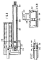
- the spring-loaded tie rod 12 is in the pre-registration dated July 21. 1987 described manner provided with a locking recess 39 into which the hook-shaped part 40 of the locking lever 41 engages.
- the locking lever 41 is provided on the side opposite the hook-like projection 39 with an extension 91 which is supported in the manner shown on the end region of the shorter lever arm 92 of the two-armed transmission lever 93.
- the transmission lever 93 is pivotally mounted on the hinge pin 94 which is arranged on a part fixed to the vehicle, for example a seat plate.
- the longer lever arm 95 of the transmission lever 93 has an upwardly angled end part 96 at its free end.
- This end part is supported on a holding and control cam 97, which is provided in the upper region of the sensor lever 98 and is pivotally mounted in its lower region on a part fixed to the vehicle, for example a seat plate.
- the bearing consists of a bearing pin 99 fixed to the vehicle.
- the sensor lever 98 carries at its upper free end a widened head 100 which forms the mass of gravity.
- a control lever 102 is pivotally mounted on a hinge pin 101 fixed to the vehicle consists of two angled guideways 103, 104.
- the two guideways open into the apex region 105, in which the control and holding cam 97 of the sensor lever 98 lies in the manner shown in FIG. 2.
- the guideways 103, 104 lie approximately symmetrically to the center line 106 of the sensor lever 98.
- the two guideways 103, 104 form acute angles with the center line 106 and are designed to rise gently.
- the control lever 105 is acted upon by a compression spring 110, the preload of which can be adjusted in a known manner by means of an adjusting screw.
- a tension spring could of course also be provided.
- the end face 111 of the upwardly angled part 96 of the transmission lever 93 is rounded, so that when the transmission lever is deflected, a force component acting in the release direction acts on it, which component can be designed to be large enough to provide the frictional forces compensated.
- a sensor lever 202 and, parallel to this, a blocking lever 203 are pivotably mounted on a frame plate or side plate of a vehicle seat on an axle pin 201.
- the sensor lever 202 is mounted in an upright position and carries the sensor mass 204 at its upper end like a hammer.
- the sensor lever 202 is held in the manner shown by a tension spring 205, which is preferably adjustable in its pretension, in contact with the stop pin 206, which on the Side plate 207 is arranged.
- the sensor lever 202 has a projecting driver pin 208.
- the blocking lever is provided with a stop lug 209 at the level of the driver pin 208. Furthermore, the blocking lever bears an abutment 210 in its central region lower stop surface on which the upwardly projecting nose 211 of the two-armed locking lever 212 is supported.
- the sensor lever 202 is pivoted out clockwise when the force resulting from the product of the acceleration and the sensor mass exceeds the force of the spring.
- the driver pin 208 hits the stop lug 209 of the blocking lever 203 after a short swivel path, which can be, for example, 2 mm, and knocks it out of its rest position, so that the locking lever 209 is released from the abutment surface of the abutment 210.
- an acceleration sensor of the type described with reference to FIG. 4 blocks a locking device which consists of the locking levers 212 and 215.
- the locking levers 212 and 215 are designed as two-armed levers and are pivotally mounted on the pins 216 and 217, which is fastened, for example, to a frame plate of a seat.
- the lever 215 is designed as an angle lever, the shorter lever arm 218 engaging with the flank 219 of its end hook 220 in an annular groove 221 with beveled flanks of the tension rod 22 of a belt tensioner.
- the locking lever 215 engages with its longer lever arm behind the hook-like stop surface 224 of the shorter lever arm of the locking lever 212.
- the lever arm lengths and the bevels of the stop surfaces are chosen such that only about a hundredth of the tensile force of the tie rod acts on the abutment 210 of the blocking lever 203.
- an essentially cylindrical sensor mass 302 is mounted in longitudinally displaceable manner in the tube piece 301.
- Sensor mass 302 is provided with axially aligned axle journals 303 which pass through aligned housing bores.
- Hat-shaped caps 304 which hold the sensor mass 301 in its rest position, are placed on the axle journals 303 passing through the housing bores.
- the axle journals 303 are guided in the hat-shaped caps 304 with radial play.
- the end faces of the axle journals 303 abut the top walls 305 which close the hat-shaped caps.
- Compression springs 308 are clamped between the flange-like edges 306 of the hat-shaped cap 304 and a housing-fixed wall 307, which hold the flange-shaped edges 306 in contact with the end-side housing walls of the housing 301.
- the sensor mass 301 is provided with an annular groove 310 in the manner shown.
- a sensor lever which in its ready position is at a distance from the annular flanks of the sensor mass, engages in this annular groove.
- This sensor lever or sensor element is therefore only acted upon by the annular groove of the sensor mass when the latter has already covered a certain distance due to accelerations that occur. If the sensor lever or sensor sensor is deflected from its rest position, it releases a part which locks the release system, for example a release lever, so that the corresponding safety device is then activated.
- an electrical switch in the form of a microswitch could also be provided.
- FIG. Grips into the groove 310 of the sensor mass 302 a sensor lever 311, which is pivotally mounted in the manner shown on the forked end of an angle piece 312 fixedly connected to the housing 301.
- This sensor lever 311 is held in its illustrated central position by holding means, not shown, with only a small holding force.
- a trigger lever 313, which releases the locking device, is supported on the shorter arm 312 of the sensor lever 311 designed as a two-armed lever.
- the end face of the shorter lever could be provided with a recess like a ratchet, so that the sensor lever 311 is held in its rest position by the force of the release lever 313 and additional holding means can be dispensed with.
Applications Claiming Priority (6)
| Application Number | Priority Date | Filing Date | Title |
|---|---|---|---|
| DE3726576 | 1987-08-01 | ||
| DE3726576 | 1987-08-10 | ||
| DE3729518 | 1987-09-03 | ||
| DE3729518 | 1987-09-03 | ||
| DE3731289 | 1987-09-17 | ||
| DE3731289 | 1987-09-17 |
Publications (3)
| Publication Number | Publication Date |
|---|---|
| EP0305765A2 true EP0305765A2 (de) | 1989-03-08 |
| EP0305765A3 EP0305765A3 (en) | 1989-12-20 |
| EP0305765B1 EP0305765B1 (de) | 1993-02-10 |
Family
ID=27196332
Family Applications (1)
| Application Number | Title | Priority Date | Filing Date |
|---|---|---|---|
| EP88112812A Expired - Lifetime EP0305765B1 (de) | 1987-08-10 | 1988-08-05 | Beschleunigungssensor für Sicherheits- und/oder Sicherheitsgurtsysteme von Kraftfahrzeugen |
Country Status (5)
| Country | Link |
|---|---|
| US (1) | US4948171A (un) |
| EP (1) | EP0305765B1 (un) |
| JP (1) | JPH01244944A (un) |
| AU (1) | AU607789B2 (un) |
| DE (1) | DE3878351D1 (un) |
Cited By (18)
| Publication number | Priority date | Publication date | Assignee | Title |
|---|---|---|---|---|
| FR2639012A1 (fr) * | 1988-11-14 | 1990-05-18 | Gen Engineering Bv | Dispositif pre-tendeur pour ceinture de securite |
| DE3844130A1 (de) * | 1988-12-28 | 1990-07-05 | Autoliv Kolb Gmbh & Co | Gurtstrammer fuer fahrzeugsicherheitsgurte |
| EP0398010A2 (de) * | 1989-05-13 | 1990-11-22 | Hs Technik + Design Technische Entwicklungen Gmbh | Verriegelungsvorrichtung und Vorrichtung zum Straffen eines Sicherheitsgurtes in einem Fahrzeug, insbesondere Kraftfahrzeug |
| WO1991004175A1 (de) * | 1989-09-16 | 1991-04-04 | Autoflug Gmbh & Co. Fahrzeugtechnik | Auslösevorrichtung für einen mechanischen energiespeicher |
| DE4027342A1 (de) * | 1989-09-25 | 1991-04-04 | Autoliv Kolb Gmbh & Co | Fahrzeugsensitiver beschleunigungssensor fuer fahrzeugsicherheitssysteme |
| FR2661145A1 (fr) * | 1990-04-23 | 1991-10-25 | Takata Corp | Mecanisme de manóoeuvre pour ceinture de securite. |
| DE4013046A1 (de) * | 1990-04-24 | 1991-10-31 | Walter Dr Knabel | Einrichtung zum ausloesen wenigstens einer sicherheitseinrichtung, z.b. eines gurtstraffers |
| EP0455859A1 (de) * | 1990-05-11 | 1991-11-13 | Trw Repa Gmbh | Ansteuermechanismus für Rückstrammeinrichtungen in Fahrzeugen |
| GB2247392A (en) * | 1990-08-22 | 1992-03-04 | Gen Engineering | Improvements in or relating to a safety-belt pre-tensioner |
| GB2250418A (en) * | 1990-12-04 | 1992-06-10 | Autoliv Dev | Improvements in or relating to a seat-belt pre-tensioner |
| EP0498001A1 (de) * | 1991-02-05 | 1992-08-12 | Trw Repa Gmbh | Rückstrammvorrichtung in einem Sicherheitsgurtsystem für Fahrzeuge |
| EP0499665A1 (de) * | 1991-02-20 | 1992-08-26 | Trw Repa Gmbh | Rückstrammvorrichtung in einem Sicherheitsgurtsystem für Fahrzeuge |
| EP0514581A1 (de) * | 1991-05-24 | 1992-11-25 | TRW Occupant Restraint Systems GmbH | Gurtstraffer für Sicherheitsgurtsysteme in Fahrzeugen |
| EP0528064A1 (de) * | 1991-08-16 | 1993-02-24 | Trw Repa Gmbh | Auslösemechanismus für Gurtstraffer |
| EP0669232A1 (de) * | 1994-02-24 | 1995-08-30 | Rahvaettevôte NORMA | Gurtstrammer für Sicherheitsgurte |
| DE4429301A1 (de) * | 1994-08-18 | 1996-02-22 | Rahvaettevote Norma Tallinn | Gurtstrammer |
| DE19629263A1 (de) * | 1995-08-15 | 1997-02-20 | Rahvaettevote Norma Tallinn | Gurtstrammer für Sicherheitsgurte |
| DE19604365B4 (de) * | 1995-02-17 | 2006-04-27 | Volkswagen Ag | Unfalldetektor |
Families Citing this family (17)
| Publication number | Priority date | Publication date | Assignee | Title |
|---|---|---|---|---|
| JPH0256059U (un) * | 1988-10-17 | 1990-04-23 | ||
| US5152552A (en) * | 1989-09-28 | 1992-10-06 | Fuji Kiko Company, Ltd. | Emergency tensioning device for automotive seat belt |
| JPH0368159U (un) * | 1989-11-09 | 1991-07-04 | ||
| JPH0446844A (ja) * | 1990-06-13 | 1992-02-17 | Takata Kk | シートベルト装置のメカニカルセンサー |
| JPH0450058A (ja) * | 1990-06-18 | 1992-02-19 | Takata Kk | シートベルト装置のプリテンショナー |
| JP2952783B2 (ja) * | 1990-06-25 | 1999-09-27 | 本田技研工業株式会社 | シートベルト緊張装置 |
| DE4119223A1 (de) * | 1991-06-11 | 1992-12-17 | Hs Tech & Design | Rueckstrammervorrichtung zum straffen eines sicherheitsgurtes in einem kraftfahrzeug |
| DE4127958A1 (de) * | 1991-08-23 | 1993-02-25 | Hs Tech & Design | Rueckstrammervorrichtung zum straffen eines sicherheitsgurtes in einem kraftfahrzeug |
| JPH0560967U (ja) * | 1992-01-27 | 1993-08-10 | 日本精工株式会社 | プリテンショナー付きシートベルト用リトラクター |
| JPH08164821A (ja) * | 1994-12-12 | 1996-06-25 | Nippondenso Co Ltd | シートベルト引き締め装置 |
| US5839790A (en) | 1995-06-06 | 1998-11-24 | Takata Inc. | Remote mechanical sensor and seat belt retractor operated thereby |
| DE19852830A1 (de) * | 1998-11-17 | 2000-05-18 | Detlef Kraus | Vorrichtung und Verfahren zur Fahrverschleiß- und Schlupfmessung an Fahrzeugen |
| US20030122363A1 (en) * | 1999-01-11 | 2003-07-03 | Olaf Muller | Operating method and system for vehicle safety device |
| US20040232670A1 (en) * | 2002-03-12 | 2004-11-25 | Trw Vehicle Safety Systems Inc. | Apparatus for measuring tension in seat belt webbing |
| US20110285115A1 (en) * | 2010-05-24 | 2011-11-24 | Gm Global Technology Operations, Inc. | Roof Rail Side Air Bag With Tensioning Tether |
| EP3450772B1 (en) | 2017-09-01 | 2024-02-14 | Enerpac Tool Group Corp. | Hybrid spring for a hydraulic cylinder |
| JP7339177B2 (ja) * | 2020-02-07 | 2023-09-05 | 株式会社東海理化電機製作所 | ウェビング巻取装置 |
Citations (3)
| Publication number | Priority date | Publication date | Assignee | Title |
|---|---|---|---|---|
| FR2349837A1 (fr) * | 1976-04-26 | 1977-11-25 | Foerenade Fabriksverken | Dispositif de detection de la deceleration d'un vehicule |
| GB2032065A (en) * | 1978-10-13 | 1980-04-30 | Lees I D M | Inertia actuator |
| WO1982003990A1 (en) * | 1981-05-20 | 1982-11-25 | Lindblad Stig Karl Gunnar | A latch mechanism for safety belts |
Family Cites Families (6)
| Publication number | Priority date | Publication date | Assignee | Title |
|---|---|---|---|---|
| US3157854A (en) * | 1962-04-03 | 1964-11-17 | Alfred B Riley | Vehicle deceleration indicator |
| US3304540A (en) * | 1965-02-17 | 1967-02-14 | Triex Inc | Vehicle deceleration caution light apparatus |
| US3372777A (en) * | 1966-03-28 | 1968-03-12 | Special Devices Inc | Inertia-operated strap lock |
| JPS51126625A (en) * | 1975-04-25 | 1976-11-04 | Toyota Motor Corp | Sheet belt system |
| BR7705009A (pt) * | 1976-08-10 | 1978-04-04 | Ferodo Sa | Dispositivo de inercia,especialmente para comandar o aferrolhamento de um enrolador-desenrolador de correia ou analogo |
| US4135683A (en) * | 1977-07-21 | 1979-01-23 | Allied Chemical Corporation | Safety belt retractor having two reels in a common housing |
-
1988
- 1988-08-01 AU AU20224/88A patent/AU607789B2/en not_active Ceased
- 1988-08-05 DE DE8888112812T patent/DE3878351D1/de not_active Expired - Fee Related
- 1988-08-05 US US07/228,999 patent/US4948171A/en not_active Expired - Fee Related
- 1988-08-05 EP EP88112812A patent/EP0305765B1/de not_active Expired - Lifetime
- 1988-08-09 JP JP88197288A patent/JPH01244944A/ja active Pending
Patent Citations (3)
| Publication number | Priority date | Publication date | Assignee | Title |
|---|---|---|---|---|
| FR2349837A1 (fr) * | 1976-04-26 | 1977-11-25 | Foerenade Fabriksverken | Dispositif de detection de la deceleration d'un vehicule |
| GB2032065A (en) * | 1978-10-13 | 1980-04-30 | Lees I D M | Inertia actuator |
| WO1982003990A1 (en) * | 1981-05-20 | 1982-11-25 | Lindblad Stig Karl Gunnar | A latch mechanism for safety belts |
Cited By (27)
| Publication number | Priority date | Publication date | Assignee | Title |
|---|---|---|---|---|
| FR2639012A1 (fr) * | 1988-11-14 | 1990-05-18 | Gen Engineering Bv | Dispositif pre-tendeur pour ceinture de securite |
| DE3844130C2 (de) * | 1988-12-28 | 2000-05-25 | Autoliv Kolb Gmbh & Co | Gurtstrammer für Fahrzeugsicherheitsgurte |
| DE3844130A1 (de) * | 1988-12-28 | 1990-07-05 | Autoliv Kolb Gmbh & Co | Gurtstrammer fuer fahrzeugsicherheitsgurte |
| EP0398010A2 (de) * | 1989-05-13 | 1990-11-22 | Hs Technik + Design Technische Entwicklungen Gmbh | Verriegelungsvorrichtung und Vorrichtung zum Straffen eines Sicherheitsgurtes in einem Fahrzeug, insbesondere Kraftfahrzeug |
| EP0398010A3 (de) * | 1989-05-13 | 1993-01-13 | Hs Technik + Design Technische Entwicklungen Gmbh | Verriegelungsvorrichtung und Vorrichtung zum Straffen eines Sicherheitsgurtes in einem Fahrzeug, insbesondere Kraftfahrzeug |
| EP0599810A3 (en) * | 1989-05-13 | 1994-06-15 | Hs Tech & Design | Device for tensioning a safety belt in a vehicle, in particular a motor vehicle. |
| EP0599810A2 (de) * | 1989-05-13 | 1994-06-01 | HS Technik und Design Technische Entwicklungen GmbH | Vorrichtung zum Straffen eines Sicherheitsgurtes in einem Fahrzeug, insbesondere Kraftfahrzeug |
| US5503037A (en) * | 1989-09-16 | 1996-04-02 | Autoliv Development Ab | Release device for mechanical energy storage means |
| US5377554A (en) * | 1989-09-16 | 1995-01-03 | Autoflug Gmbh & Co. Fahrzeugtechnik | Release device for a mechanical energy storage means |
| WO1991004175A1 (de) * | 1989-09-16 | 1991-04-04 | Autoflug Gmbh & Co. Fahrzeugtechnik | Auslösevorrichtung für einen mechanischen energiespeicher |
| DE4027342A1 (de) * | 1989-09-25 | 1991-04-04 | Autoliv Kolb Gmbh & Co | Fahrzeugsensitiver beschleunigungssensor fuer fahrzeugsicherheitssysteme |
| FR2661145A1 (fr) * | 1990-04-23 | 1991-10-25 | Takata Corp | Mecanisme de manóoeuvre pour ceinture de securite. |
| DE4013046A1 (de) * | 1990-04-24 | 1991-10-31 | Walter Dr Knabel | Einrichtung zum ausloesen wenigstens einer sicherheitseinrichtung, z.b. eines gurtstraffers |
| EP0455859A1 (de) * | 1990-05-11 | 1991-11-13 | Trw Repa Gmbh | Ansteuermechanismus für Rückstrammeinrichtungen in Fahrzeugen |
| GB2247392B (en) * | 1990-08-22 | 1994-08-03 | Gen Engineering | Improvements in or relating to a safety-belt pre-tensioner |
| GB2247392A (en) * | 1990-08-22 | 1992-03-04 | Gen Engineering | Improvements in or relating to a safety-belt pre-tensioner |
| GB2250418B (en) * | 1990-12-04 | 1994-06-08 | Autoliv Dev | Improvements in or relating to a seat-belt pre-tensioner |
| GB2250418A (en) * | 1990-12-04 | 1992-06-10 | Autoliv Dev | Improvements in or relating to a seat-belt pre-tensioner |
| EP0498001A1 (de) * | 1991-02-05 | 1992-08-12 | Trw Repa Gmbh | Rückstrammvorrichtung in einem Sicherheitsgurtsystem für Fahrzeuge |
| EP0499665A1 (de) * | 1991-02-20 | 1992-08-26 | Trw Repa Gmbh | Rückstrammvorrichtung in einem Sicherheitsgurtsystem für Fahrzeuge |
| EP0514581A1 (de) * | 1991-05-24 | 1992-11-25 | TRW Occupant Restraint Systems GmbH | Gurtstraffer für Sicherheitsgurtsysteme in Fahrzeugen |
| US5374080A (en) * | 1991-05-24 | 1994-12-20 | Trw Repa Gmbh | Safety belt pretensioner for safety belt systems in vehicles |
| EP0528064A1 (de) * | 1991-08-16 | 1993-02-24 | Trw Repa Gmbh | Auslösemechanismus für Gurtstraffer |
| EP0669232A1 (de) * | 1994-02-24 | 1995-08-30 | Rahvaettevôte NORMA | Gurtstrammer für Sicherheitsgurte |
| DE4429301A1 (de) * | 1994-08-18 | 1996-02-22 | Rahvaettevote Norma Tallinn | Gurtstrammer |
| DE19604365B4 (de) * | 1995-02-17 | 2006-04-27 | Volkswagen Ag | Unfalldetektor |
| DE19629263A1 (de) * | 1995-08-15 | 1997-02-20 | Rahvaettevote Norma Tallinn | Gurtstrammer für Sicherheitsgurte |
Also Published As
| Publication number | Publication date |
|---|---|
| EP0305765A3 (en) | 1989-12-20 |
| JPH01244944A (ja) | 1989-09-29 |
| AU607789B2 (en) | 1991-03-14 |
| EP0305765B1 (de) | 1993-02-10 |
| DE3878351D1 (de) | 1993-03-25 |
| US4948171A (en) | 1990-08-14 |
| AU2022488A (en) | 1989-02-02 |
Similar Documents
| Publication | Publication Date | Title |
|---|---|---|
| EP0305765A2 (de) | Beschleunigungssensor für Sicherheits- und/oder Sicherheitsgurtsysteme von Kraftfahrzeugen | |
| DE2826286C2 (de) | Sicherheitsgurtaufrollautomat | |
| EP0300469A1 (de) | Gurtstrammer für Fahrzeugsicherheitsgurte | |
| WO1991004175A1 (de) | Auslösevorrichtung für einen mechanischen energiespeicher | |
| EP0452521B1 (de) | Ansteuermechanismus für Rückstrammeinrichtungen in Fahrzeugen | |
| WO1990010397A1 (de) | Schocksicherer sicherheitsgurtverschluss | |
| DE19653510A1 (de) | Gurtkraftbegrenzende Einrichtung für einen Sicherheitsgurt | |
| EP0569886A1 (de) | Schloss für Fahrzeug-Sicherheitsgurtsysteme | |
| EP1541425B1 (de) | Haltevorrichtung für eine Fahrzeugsicherheitsvorrichtung | |
| EP0242859A2 (de) | Gleitschienenführung für Fahrzeugsitze | |
| DE2643051A1 (de) | Sicherheitsgurtaufroller | |
| EP0186105A2 (de) | Selbstsonsorische Klemmvorrichtung für ein Sicherheitsgurtsystem | |
| DE3332664C2 (un) | ||
| DE3229304A1 (de) | Rueckstrammer fuer ein sicherheitsgurtsystem fuer kraftfahrzeuge | |
| DE3841811C2 (un) | ||
| DE4007915C2 (de) | Gurtverschluß mit Massenausgleich | |
| DE3624569C2 (un) | ||
| DE2821152A1 (de) | Aufwickelvorrichtung fuer sicherheitsgurte von fahrzeugen, insbesondere personenkraftfahrzeugen | |
| DE19922626B4 (de) | Längseinstellvorrichtung für einen Fahrzeugsitz | |
| DE3804177A1 (de) | Sicherheitseinrichtung | |
| DE3705846A1 (de) | Automatisches sicherheitsgurt-notloesesystem | |
| DE19539439C2 (de) | Klemmvorrichtung | |
| DE3513113C2 (de) | Sicherheitsgurt-Rückhaltevorrichtung | |
| DE3706367A1 (de) | Vorrichtung zur selbsttaetigen hoehenverstellung des umlenkbeschlages eines sicherheitsgurtes in fahrzeugen | |
| DE19752338C2 (de) | Sicherheits-Blockiereinrichtung mit auf Gurtbandauszug abgestimmter Selbstblockadeverhinderung |
Legal Events
| Date | Code | Title | Description |
|---|---|---|---|
| PUAI | Public reference made under article 153(3) epc to a published international application that has entered the european phase |
Free format text: ORIGINAL CODE: 0009012 |
|
| AK | Designated contracting states |
Kind code of ref document: A2 Designated state(s): DE ES FR GB IT SE |
|
| RIN1 | Information on inventor provided before grant (corrected) |
Inventor name: KNABEL, WALTER, DR. Inventor name: WENTKER, STEPHAN Inventor name: MAYER, JOSEF Inventor name: NOTAR, WALTER |
|
| PUAL | Search report despatched |
Free format text: ORIGINAL CODE: 0009013 |
|
| AK | Designated contracting states |
Kind code of ref document: A3 Designated state(s): DE ES FR GB IT SE |
|
| 17P | Request for examination filed |
Effective date: 19891114 |
|
| 17Q | First examination report despatched |
Effective date: 19910204 |
|
| RAP1 | Party data changed (applicant data changed or rights of an application transferred) |
Owner name: AUTOLIV-KOLB GMBH & CO. |
|
| GRAA | (expected) grant |
Free format text: ORIGINAL CODE: 0009210 |
|
| AK | Designated contracting states |
Kind code of ref document: B1 Designated state(s): DE ES FR GB IT SE |
|
| PG25 | Lapsed in a contracting state [announced via postgrant information from national office to epo] |
Ref country code: IT Free format text: LAPSE BECAUSE OF FAILURE TO SUBMIT A TRANSLATION OF THE DESCRIPTION OR TO PAY THE FEE WITHIN THE PRE;WARNING: LAPSES OF ITALIAN PATENTS WITH EFFECTIVE DATE BEFORE 2007 MAY HAVE OCCURRED AT ANY TIME BEFORE 2007. THE CORRECT EFFECTIVE DATE MAY BE DIFFERENT FROM THE ONE RECORDED.SCRIBED TIME-LIMIT Effective date: 19930210 Ref country code: ES Free format text: THE PATENT HAS BEEN ANNULLED BY A DECISION OF A NATIONAL AUTHORITY Effective date: 19930210 Ref country code: FR Effective date: 19930210 Ref country code: GB Effective date: 19930210 Ref country code: SE Effective date: 19930210 |
|
| REF | Corresponds to: |
Ref document number: 3878351 Country of ref document: DE Date of ref document: 19930325 |
|
| EN | Fr: translation not filed | ||
| GBV | Gb: ep patent (uk) treated as always having been void in accordance with gb section 77(7)/1977 [no translation filed] |
Effective date: 19930210 |
|
| PLBE | No opposition filed within time limit |
Free format text: ORIGINAL CODE: 0009261 |
|
| STAA | Information on the status of an ep patent application or granted ep patent |
Free format text: STATUS: NO OPPOSITION FILED WITHIN TIME LIMIT |
|
| 26N | No opposition filed | ||
| PGFP | Annual fee paid to national office [announced via postgrant information from national office to epo] |
Ref country code: DE Payment date: 19940928 Year of fee payment: 7 |
|
| PG25 | Lapsed in a contracting state [announced via postgrant information from national office to epo] |
Ref country code: DE Effective date: 19960501 |