EP0293168B1 - Ofen mit einem Strahlrohrbrenner mit zweistufiger Brennstoffzufuhr - Google Patents
Ofen mit einem Strahlrohrbrenner mit zweistufiger Brennstoffzufuhr Download PDFInfo
- Publication number
- EP0293168B1 EP0293168B1 EP88304688A EP88304688A EP0293168B1 EP 0293168 B1 EP0293168 B1 EP 0293168B1 EP 88304688 A EP88304688 A EP 88304688A EP 88304688 A EP88304688 A EP 88304688A EP 0293168 B1 EP0293168 B1 EP 0293168B1
- Authority
- EP
- European Patent Office
- Prior art keywords
- primary
- combustion
- radiant tube
- burner
- fuel
- Prior art date
- Legal status (The legal status is an assumption and is not a legal conclusion. Google has not performed a legal analysis and makes no representation as to the accuracy of the status listed.)
- Expired - Lifetime
Links
- 239000000446 fuel Substances 0.000 title claims description 123
- 238000002485 combustion reaction Methods 0.000 claims description 157
- 239000000567 combustion gas Substances 0.000 claims description 56
- 230000001172 regenerating effect Effects 0.000 claims description 32
- 239000011819 refractory material Substances 0.000 claims description 17
- 238000002347 injection Methods 0.000 claims description 16
- 239000007924 injection Substances 0.000 claims description 16
- 238000000034 method Methods 0.000 claims description 9
- QVGXLLKOCUKJST-UHFFFAOYSA-N atomic oxygen Chemical compound [O] QVGXLLKOCUKJST-UHFFFAOYSA-N 0.000 claims description 8
- 229910052760 oxygen Inorganic materials 0.000 claims description 8
- 239000001301 oxygen Substances 0.000 claims description 8
- 230000001419 dependent effect Effects 0.000 claims 1
- 239000007789 gas Substances 0.000 description 14
- 239000000919 ceramic Substances 0.000 description 8
- 239000012212 insulator Substances 0.000 description 7
- 239000000463 material Substances 0.000 description 7
- 238000009792 diffusion process Methods 0.000 description 4
- 230000003628 erosive effect Effects 0.000 description 4
- 239000002184 metal Substances 0.000 description 4
- 229910052751 metal Inorganic materials 0.000 description 4
- 238000013021 overheating Methods 0.000 description 4
- 238000005336 cracking Methods 0.000 description 2
- 239000011491 glass wool Substances 0.000 description 2
- 230000035699 permeability Effects 0.000 description 2
- 230000002265 prevention Effects 0.000 description 2
- 229910000838 Al alloy Inorganic materials 0.000 description 1
- OKTJSMMVPCPJKN-UHFFFAOYSA-N Carbon Chemical compound [C] OKTJSMMVPCPJKN-UHFFFAOYSA-N 0.000 description 1
- 229910000599 Cr alloy Inorganic materials 0.000 description 1
- 229910000640 Fe alloy Inorganic materials 0.000 description 1
- 235000009781 Myrtillocactus geometrizans Nutrition 0.000 description 1
- 240000009125 Myrtillocactus geometrizans Species 0.000 description 1
- BPQQTUXANYXVAA-UHFFFAOYSA-N Orthosilicate Chemical compound [O-][Si]([O-])([O-])[O-] BPQQTUXANYXVAA-UHFFFAOYSA-N 0.000 description 1
- VYPSYNLAJGMNEJ-UHFFFAOYSA-N Silicium dioxide Chemical compound O=[Si]=O VYPSYNLAJGMNEJ-UHFFFAOYSA-N 0.000 description 1
- 238000003915 air pollution Methods 0.000 description 1
- PNEYBMLMFCGWSK-UHFFFAOYSA-N aluminium oxide Inorganic materials [O-2].[O-2].[O-2].[Al+3].[Al+3] PNEYBMLMFCGWSK-UHFFFAOYSA-N 0.000 description 1
- 229910052799 carbon Inorganic materials 0.000 description 1
- 238000006243 chemical reaction Methods 0.000 description 1
- 238000009841 combustion method Methods 0.000 description 1
- 238000010276 construction Methods 0.000 description 1
- 238000011109 contamination Methods 0.000 description 1
- 238000005260 corrosion Methods 0.000 description 1
- 230000007797 corrosion Effects 0.000 description 1
- 230000003247 decreasing effect Effects 0.000 description 1
- 230000000694 effects Effects 0.000 description 1
- 238000005516 engineering process Methods 0.000 description 1
- 238000010304 firing Methods 0.000 description 1
- 239000005350 fused silica glass Substances 0.000 description 1
- 230000005923 long-lasting effect Effects 0.000 description 1
- 239000000203 mixture Substances 0.000 description 1
- -1 nitride silicate Chemical class 0.000 description 1
- 230000002035 prolonged effect Effects 0.000 description 1
- 230000035939 shock Effects 0.000 description 1
- HBMJWWWQQXIZIP-UHFFFAOYSA-N silicon carbide Chemical compound [Si+]#[C-] HBMJWWWQQXIZIP-UHFFFAOYSA-N 0.000 description 1
- 229910010271 silicon carbide Inorganic materials 0.000 description 1
- 239000007787 solid Substances 0.000 description 1
- 239000000725 suspension Substances 0.000 description 1
- 230000001360 synchronised effect Effects 0.000 description 1
Images
Classifications
-
- F—MECHANICAL ENGINEERING; LIGHTING; HEATING; WEAPONS; BLASTING
- F23—COMBUSTION APPARATUS; COMBUSTION PROCESSES
- F23C—METHODS OR APPARATUS FOR COMBUSTION USING FLUID FUEL OR SOLID FUEL SUSPENDED IN A CARRIER GAS OR AIR
- F23C3/00—Combustion apparatus characterised by the shape of the combustion chamber
- F23C3/002—Combustion apparatus characterised by the shape of the combustion chamber the chamber having an elongated tubular form, e.g. for a radiant tube
-
- F—MECHANICAL ENGINEERING; LIGHTING; HEATING; WEAPONS; BLASTING
- F23—COMBUSTION APPARATUS; COMBUSTION PROCESSES
- F23C—METHODS OR APPARATUS FOR COMBUSTION USING FLUID FUEL OR SOLID FUEL SUSPENDED IN A CARRIER GAS OR AIR
- F23C6/00—Combustion apparatus characterised by the combination of two or more combustion chambers or combustion zones, e.g. for staged combustion
- F23C6/04—Combustion apparatus characterised by the combination of two or more combustion chambers or combustion zones, e.g. for staged combustion in series connection
- F23C6/042—Combustion apparatus characterised by the combination of two or more combustion chambers or combustion zones, e.g. for staged combustion in series connection with fuel supply in stages
-
- F—MECHANICAL ENGINEERING; LIGHTING; HEATING; WEAPONS; BLASTING
- F23—COMBUSTION APPARATUS; COMBUSTION PROCESSES
- F23L—SUPPLYING AIR OR NON-COMBUSTIBLE LIQUIDS OR GASES TO COMBUSTION APPARATUS IN GENERAL ; VALVES OR DAMPERS SPECIALLY ADAPTED FOR CONTROLLING AIR SUPPLY OR DRAUGHT IN COMBUSTION APPARATUS; INDUCING DRAUGHT IN COMBUSTION APPARATUS; TOPS FOR CHIMNEYS OR VENTILATING SHAFTS; TERMINALS FOR FLUES
- F23L15/00—Heating of air supplied for combustion
- F23L15/02—Arrangements of regenerators
-
- F—MECHANICAL ENGINEERING; LIGHTING; HEATING; WEAPONS; BLASTING
- F23—COMBUSTION APPARATUS; COMBUSTION PROCESSES
- F23C—METHODS OR APPARATUS FOR COMBUSTION USING FLUID FUEL OR SOLID FUEL SUSPENDED IN A CARRIER GAS OR AIR
- F23C2201/00—Staged combustion
- F23C2201/30—Staged fuel supply
-
- Y—GENERAL TAGGING OF NEW TECHNOLOGICAL DEVELOPMENTS; GENERAL TAGGING OF CROSS-SECTIONAL TECHNOLOGIES SPANNING OVER SEVERAL SECTIONS OF THE IPC; TECHNICAL SUBJECTS COVERED BY FORMER USPC CROSS-REFERENCE ART COLLECTIONS [XRACs] AND DIGESTS
- Y02—TECHNOLOGIES OR APPLICATIONS FOR MITIGATION OR ADAPTATION AGAINST CLIMATE CHANGE
- Y02E—REDUCTION OF GREENHOUSE GAS [GHG] EMISSIONS, RELATED TO ENERGY GENERATION, TRANSMISSION OR DISTRIBUTION
- Y02E20/00—Combustion technologies with mitigation potential
- Y02E20/34—Indirect CO2mitigation, i.e. by acting on non CO2directly related matters of the process, e.g. pre-heating or heat recovery
-
- Y—GENERAL TAGGING OF NEW TECHNOLOGICAL DEVELOPMENTS; GENERAL TAGGING OF CROSS-SECTIONAL TECHNOLOGIES SPANNING OVER SEVERAL SECTIONS OF THE IPC; TECHNICAL SUBJECTS COVERED BY FORMER USPC CROSS-REFERENCE ART COLLECTIONS [XRACs] AND DIGESTS
- Y10—TECHNICAL SUBJECTS COVERED BY FORMER USPC
- Y10T—TECHNICAL SUBJECTS COVERED BY FORMER US CLASSIFICATION
- Y10T428/00—Stock material or miscellaneous articles
- Y10T428/24—Structurally defined web or sheet [e.g., overall dimension, etc.]
- Y10T428/24149—Honeycomb-like
Definitions
- the present invention relates to a a furnace with a radiant tube burner assembly.
- a radiant tube burner is presented in US Patent No. 4,604,051 where a set of burners equipped with regenerative beds is installed at both ends of a radiant tube, and these burners are operated alternatively to preheat the combustion air using heat accumulated in the non-operated burner side of the regenerative bed.
- the conical type regenerative bed 102 is placed inside of the burner shell 104 which surrounds the fuel nozzle 103 protruding into the radiant tube 101 at the outside of the furnace, whereby through the regenerative bed 102 the combustion air is supplied to the combustion chamber and the combustion gas is exhausted.
- the same Figure 10 shows the furnace wall 105, the forced draft fan 106, the reversing valve 107, and the ejector 108.
- a Two Stage Fuel Supply Burner has been considered effective in order to reduce Nox emission in the combustion system.
- Such a technique as applied to an open flame type burner is known by US-A-. 4,505,666.
- a portion of fuel and all of the combustion air is supplied to a primary combustion chamber, which causes rapid combustion under a high excess air ratio, and also slow and gentle combustion of the remaining fuel (a secondary fuel) using the low content of residual oxygen in the primary combustion gas, following the heat diffusion of the primary gas from the outer edge of the primary combustion chamber to the furnace.
- This two stage fuel supply combustion burner is considered capable of achieving low NOx performance.
- the purpose of this invention is to provide a low NOx radiant tube burner.
- the purpose of this invention is to provide a long lasting radiant tube burner without danger of thermal erosion or rupturing a fuel nozzle.
- the purpose of this invention is to provide an appropriate radiant tube burner for a gas system of recovering heat from an exhaust combustion gas.
- the fuel nozzle is set out from the exhaust gas passage and the secondary fuel nozzle is encompassed with refractory materials to avoid direct encounter with the high temperature combustion gas, thereby protecting thermal erosion or a fuel cracking on the fuel nozzles.
- the secondary fuel nozzle is placed approximately on the axis of the primary combustion chamber, whereby the second combustion flame is surrounded by the primary combustion gas such that the flame is prevented from directly contacting with inner wall of the radiant tube, thus local overheating in the radiant tube is prevented and therefore the life of the tube is prolonged.
- a long flame may be formed in the radiant tube by enlarging the flow passage area of the primary combustion gas without changing the diameter of the tube in order to reduce the primary combustion gas flow velocity, thereby causing the mixing of the primary combustion gas and the secondary combustion gas to be moderated. This helps to contribute to the prevention of local overheating in the tube and provides uniform thermal distribution even when applying an installed radiant tube or in the case when the diameter of the tube is not changed.
- the refractory materials structured in the primary combustion chamber which is inserted into the radiant tube, protects the bung portion of the radiant tube and also prevents contact with the primary combustion gas. The result prevents rupturing of the radiant tube at the bung.
- the secondary fuel nozzle protrudes from the primary combustion chamber, which generates self-recirculation in the combustion gas, so that NOx emission is more reduced.
- the secondary fuel nozzle is located approximately on the axis of the primary combustion chamber and it injects a secondary combustion fuel both in the axial and in the radial directions of the tube.
- a secondary combustion is generated by the primary combustion gas and the radially injected fuel; and, furthermore, a third combustion is also generated by the axially injected fuel and the secondary combustion gas.
- This is a so called three stage combustion system, and is essentially effective in reducing the NOx emissions and provides for uniform temperature distribution along the radiant tube. According to experimental results, we found the Nox emission is maintained lower than 100 ppm in this construction.
- a recuperator attached to one end of the radiant tube receives the exhaust combustion gas from the tube, and supplies preheated combustion air to the burner which is installed at the other end of the tube.
- this invention discloses a radiant tube burner which has a set of burners placed at both end of radiant tube, wherein said each burner has a primary combustion chamber which is placed outside of the furnace and of which the combustion gas injection outlet located approximately more inside of the furnace than the bung of the radiant tube; a primary fuel nozzle which injects the primary fuel into the primary combustion chamber and which is located away from the exhaust gas passage and a secondary fuel nozzle which is surrounded with refractory materials and which injects the secondary fuel into the radiant tube adjacent to the combustion gas injection outlet; and allows to create primary combustion by supplying the primary fuel and almost the total amount of combustion air into the primary combustion chamber and the secondary combustion with the secondary fuel by combining the secondary fuel with low concentrated oxygen remaining in the generated primary combustion gas; and each burner is connected through a regenerative bed selectively either to an air supply system for combustion or to an exhaust combustion gas system, whereby the burners operate alternatively by supplying the combustion air through the regenerative bed or to exhaust the combustion gas through the regenerative bed.
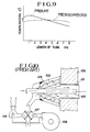
- this invention leads to obtaining an uniform temperature distribution along the radiant tube as shown in Figure 9.
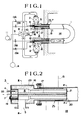
- Figure 1 is a schematic illustration of one embodiment of the present invention illustrating a radiant tube burner.
- This radiant tube burner contains a pair of burners 3 each of which is connected to one end of a radiant tube 1. Each of these burners is alternately connected to the combustion air supply system 9 and to the combustion gas exhaust system 10 respectively intermediated by regenerative bed 2. Burners are alternatively operated in fire or in flue mode. The combustion exhaust gas is exhausted through the regenerative bed 2 where the associated burner is not being operated. On the other hand the combustion air is supplied through the regenerative bed 2 where the associated burner is being operated.
- Each of the previously mentioned burners 3 consists of a primary nozzle 4 which injects a portion of the fuel called the primary fuel, a combustion air duct 5 which injects the full amount of combustion air, a primary combustion chamber 6 wherein the primary fuel is burned with the full amount of combustion air under a high excess air ratio, and a secondary fuel nozzle 7 which injects the remaining fuel called the secondary fuel directly in to the radiant tube at the outlet of the fired primary combustion chamber or at the combustion gas injection outlet 21.
- the combustion air duct 5 is connected to the regenerative bed 2, so that both the exhaust of combustion gas and the supply of the combustion air passes through the regenerative bed 2.
- the secondary combustion is created by using the remaining allocation of fuel which is injected from secondary fuel nozzle 7 and the residual oxygen in the primary combustion gas which is not consumed on the primary combustion.
- the fuel ratio supplied to the nozzle in the primary combustion chamber 6 and to the nozzle in the radiant tube 1 is commonly 5 to 50% for primary fuel and 95 to 50% for the secondary fuel.
- the preferable ratio is 20% for the primary fuel and 80% for the secondary fuel.
- the total amount of combustion air is supplied to the primary combustion chamber 6.
- a small amount of the combustion air 5 to 10%, could be injected directly into the radiant tube 1 where it is ignited by the secondary fuel so long as the two stage fuel supply combustion concept can accommodate the excess combustion air.
- the regenerative bed 2 is alternately connected to the combustion air supply system 9 and the combustion gas exhaust system 10 through the four direction reversing valve 8.
- the combustion air is supplied by the forced draft fan 11 of the combustion air supply system 9 through the fired regenerative bed 2 of operated burner 3, and the combustion gas is drafted by the induced fan 12 through the non-fired regenerative bed 2 of the non-operated burner 3.
- the flow of combustion air and combustion gas is controlled either by a timer (not shown in the drawing) operating at specific intervals or by measuring the exhaust gas temperature using a thermal detector (not shown in the drawing). If the measured temperature reaches a specific limit or if the set time interval is reached, then the reversing valve 8 redirects the flow of combustion air and this operation is synchronized with changing the supply of fuel.
- the fuel supply source 14 provides fuel through a magnetic solenoid valve 13A which is connected to a primary fuel nozzle 4 and another magnetic solenoid valve 13B which is connected to a secondary fuel nozzle 7.
- a magnetic solenoid valve 13A which is connected to a primary fuel nozzle 4
- another magnetic solenoid valve 13B which is connected to a secondary fuel nozzle 7.
- the previously mentioned primary fuel nozzle 4 should be located at the back of the primary combustion chamber 6, which is set outside of the furnace 14, so as to be away from the combustion gas exhaust passage and, therefore avoid direct contact with the combustion gas.
- This particular embodiment has a primary fuel nozzle 4 embedded into the back wall of the insulating firebrick 22 of the primary combustion chamber 6 and having the only outlet of the nozzle opened to the primary combustion chamber 6.
- a pilot burner 18 is provided near the primary fuel nozzle 4.
- the numeral 19 indicates a sight hole.
- the secondary fuel nozzle 7 is centred on the central axis of the primary combustion chamber 6 and injects the secondary fuel into the radiant tube at the outlet of the primary combustion chamber 6, i.e. at the combustion gas injection outlet 21.
- the secondary fuel nozzle 7, in detail description, is located in centre of the primary combustion chamber 6 which is made of castable refractory material 16, protected by refractory insulator 17. In this preferred embodiment, a light-weight and less expensive glass wool cylinder is applied and held by the secondary fuel nozzle 7. The method is not limited by the above description.
- the insulator 17 could be made of formed castable refractory material or carbon silicate ceramics and inside of it, the secondary fuel nozzle 7 can be embedded; or, the secondary fuel nozzle 7 can be made of refractory materials such as fused quartz or fine ceramics in which case, the extra insulator may not be required.
- the secondary fuel nozzle 7 is held by the back wall portion 22 of the primary combustion chamber 6 at one end and the other end is held at castable refractory material 16 by cross shaped suspension frame 20.
- the back wall portion 22 is separately fabricated to be removable from the main body 16 of the primary combustion chamber 6, wherefore the insulator 17 is able to replace and maintain.
- the primary combustion chamber 6 has a cylindrical shape and is usually made of refractory material such as, for example, castable refractory, silicon carbide type ceramics, nitride silicate type ceramics, or sialon (Si 6-z Al z O z N 8-z ) type ceramics.
- the primary combustion chamber 6 is structured castable refractory material 16.
- the castable refractory material 16 is covered by heat-proof metal member 23 which has a flange to attached to the radiant tube 1.
- the primary combustion chamber 6 is made of castable refractory material 16 and covered with heat-proof metal member which has two portions where one portion is called the back wall 22 can be separated from the other portion for easy replacement of the secondary fuel nozzle 7 and the insulator 17.
- the injection outlet 21 of the primary combustion chamber 6 is located approximately more inside of the furnace 14 than the bung portion 25 of the radiant tube 1.
- the "approximately more inside” point should be understood as a point which is at essentially more inside of furnace than the bung portion 25, or at the same surface of the furnace inner wall or even at slightly more concaved inside than the furnace inner wall.
- the regenerative bed 2 is to accumulate temporary sensible heat from the combustion exhaust gas and could be made from any materials or by any kind of structural methods as long as the materials/methods do not cause either reaction with the combustion gas or provide any bad effects to the combustion air.
- Materials for the regenerative bed 2 in general, need to meet the following requirements; large area for the heat transfer, small pressure loss, resistance to high temperature, resistance to thermal shock, and resistance to corrosion.
- ceramics such as alumina, or heat-proof metal has been used.
- honeycomb ceramics having many honeycomb shapes holes in the direction of gas flow have been used as the regenerative bed materials.
- a gas permeable, regenerative bed means not only that the material has many holes as a characteristic or in itself, but, also the material can hold permeability within the structure, even if no specific method is set aside for permeability. Therefore, it is possible to make a permeable, solid structure where the combustion exhaust gas temperature is as high as 1,000°C, with heat-proof metal wire, such as FCH-2 made of Fe, Cr, and Al alloy netted as a wire gauze and then piled up in appropriate thickness.
- This kind of regenerative bed material can be packed in the combustion air duct 5 or be a cartridge type which provides for easy replacement.
- the configuration of the radiant tube 1 need not be a certain shape such as straight type, U type, T type, W type, O type, or L type known to be in the Prior Art. It could be a new style.
- the radiant tube burner describe and structured above is operated as follows:- At first, one of burners 3 is fired with combustion air supplied by the forced draft fan 11. At the same time, high temperature combustion gas in the radiant tube 1 is exhausted through the combustion air duct 5 of the non-operated burner 3 by the pull draft operation of the induced fan 12. The heat from the combustion gas exhausted is recovered while passing through the regenerative bed 2. After defined time interval, the burner which has been operated is allowed to rest, on the other hand, the non-operative burner 3 starts combustion. The combustion gas is exhausted through the regenerative bed 2 associated with burner 3 which has been in the operational or fired mode and now is in the non-operation mode.
- the combustion air absorbs the heat which has been provided by the exhaust gas and accumulated to the regenerative bed 2 which has been on the non-operated side from the regenerative bed 2 and then is supplied to burner in preheated condition at, for example, 700 to 1,000°C.
- the temperature of the radiant tube 1 and the regenerative bed 2 is increased gradually by means of changing combustion and exhaust alternately until the set temperature of both the radiant tube and the regenerative bed is achieved. Then the system of combustion stays in constant operation.
- the alternate change of combustion air and the combustion gas is carried out at appropriate time intervals, such as every 20 seconds to 5 minutes, or when the temperature of the exhausted combustion gas reaches a set value, such as about 200°C.
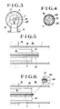
- Figure 5 illustrates the other embodiment of the secondary fuel nozzle.
- the secondary fuel nozzle 7 surrounded with the insulator 17 made of light weight refractory materials such as glass wool is protruded from the primary combustion chamber 6 to improve on low NOx performance. If the length of the protrusion is too large, the nozzle 7 tends to bend downward due to the heat. On the other hand, if the length is too small, low NOx performance cannot be achieved. Therefore, the protrusion of the secondary fuel nozzle as well as the insulator 17 from the primary combustion chamber is about 50 to 300 mm, and preferably about 200 mm in length.
- the protrusion type secondary fuel nozzle achieves better low NOx performance compared with the embodiment shown in Figure 1, since self-recirculation flow of the combustion gas occurs around the secondary nozzle.
- Figure 6 illustrates characteristics of the secondary fuel nozzle in yet another embodiment of the present invention.
- the secondary fuel nozzle 7 is protruded slightly out from the primary combustion chamber 6 into the radiant tube 1 and has one injection outlet 24 at the end in the axial direction and a few injection outlets 24 in radial direction.
- the fuel injected in the radial direction through the radial outlets 24 creates secondary combustion with a low oxygen concentration (about 17%) of combustion air which remains in the primary combustion gas, and then the fuel injected in the axial direction through the axial outlet 24 creates third combustion with the further low-concentrated oxygen remaining combustion air (about 11%).
- the three stage fuel supply combustion occurs in this embodiment.
- the amount of the primary fuel becomes nearly zero or sometimes completely zero.
- the secondary combustion and the third combustion represents, in fact, a two stage, fuel supply combustion.
- the operable fuel distribution in this case is about 5 to 50% for the primary fuel and 95 to 50% for the secondary fuel which includes the fuel for the third combustion.
- the preferable fuel ratio is about 20% for the primary and 80% for the secondary (considering 40% for the secondary and 60% for the third combustion in the case of the three-stage assuming that the secondary fuel considered as 100%).
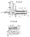
- Figure 7 illustrates another embodiment of this invention.
- a burner consists of; a primary fuel nozzle 4 which injects portion of fuel (primary fuel), a combustion air duct 5 which injects a full amount of combustion air to the primary combustion chamber 6 in tangential direction of the cylindrical chamber, the primary combustion chamber 6 wherein the portion of fuel and the full amount of the combustion air are combusted in laminar diffusion combustion under high excess air ratio, and a secondary fuel nozzle 7 which injects remaining fuel (secondary fuel) into the radiant tube 1 circumferentially at the outlet of the primary combustion chamber 6.
- primary fuel nozzle 4 which injects portion of fuel (primary fuel)
- a combustion air duct 5 which injects a full amount of combustion air to the primary combustion chamber 6 in tangential direction of the cylindrical chamber, the primary combustion chamber 6 wherein the portion of fuel and the full amount of the combustion air are combusted in laminar diffusion combustion under high excess air ratio
- secondary fuel nozzle 7 which injects remaining fuel (secondary fuel) into the radiant tube 1 circumfer
- the small amount of fuel is injected to and enveloped in the layer of the rotating combustion air which injected from the combustion air duct 5 into the primary combustion chamber 6, which creates a laminar diffusion combustion.
- a long flame formed by the combustion reaches radiant tube 1.
- the secondary combustion occurs in the radiant tube both with the balance of fuel which injected from the secondary fuel nozzle 7 and the oxygen remaining the primary combustion gas.
- the primary fuel nozzle 4 should be located at the back of the primary combustion chamber 6, which is set outside of the furnace 14 so as to be away from the combustion gas exhaust passage and, therefore avoid direct contact to combustion gas.
- the primary fuel nozzle 4 is embedded into the back wall 22 of the primary combustion chamber 6 made of castable refractory material and only the tip of the nozzle is opened to the primary combustion chamber 6.
- the primary combustion fuel nozzle 4 also acts as a pilot burner.
- the secondary fuel nozzle 7 is embedded into the primary combustion chamber which constructed of castable refractory 16 has an injection outlet opening in parallel with the primary combustion gas injection outlet 21 at the end of castable refractory 16 constructed chamber 6.
- the secondary fuel nozzle 7 is located further inside of the furnace 14 than the furnace wall 15 and has a plurality of openings, for example four openings, circumferentially to the primary combustion gas injection outlet 21. This configuration provides the best result for low NOx performance and empirical results reached under 100 ppm of the NOx emissions. But, in other hand, if the diameter of the primary combustion chamber 6 becomes smaller, the fuel and the combustion air mixture and diffusion becomes better and the flame tends to become diverged and shorter.
- FIG 8 illustrates a radiant tube burner with recuperator of other embodiment of the present invention.
- a radiant tube 1 is equipped with a burner 3 at one end and a recuperator 30 at another end which preheats the combustion air using the exhaust combustion gas.
- the temperature of the combustion gas in the radiant tube burner commonly is about 1,000°C.
- the exhaust temperature may be decreased to about 500°C and the combustion air may be preheated to between about 350 and 450°C.
- the recuperator 30 is constructed, for example, with double wall tubings inserted into the radiant tube 1. During the combustion air introduced into the inner tube 31 transfers to the outer tube 32 passing through the open top end of the inner tube 31. Heat exchange between the combustion air and the combustion gas which flows in the radiant tube 1 with surrounding the recuperator 30 through the wall of the outer tube 32 of the recuperator 30 takes place.
- the outer tube 32 of the recuperator 30 is connected by a connecting tube 33 to the combustion air supply duct 5 of the burner 3 located on the opposite side for supplying the preheated combustion air.
- the burner 3 has the secondary fuel nozzle 7 which is placed on the axis of the primary combustion chamber 6, but it is not limited by the position of the nozzle and it is possible to have a secondary fuel nozzles 7 which are embedded into the castable refractory 16 nozzles 7 which are embedded into the castable refractory 16 formed the primary combustion chamber 6 (see Figure 7).
- the thermal efficiency becomes high since the combustion exhaust gas from the other end is used to preheat the combustion air.
- the radiant tube burner in this invention does not recover heat using the regenerative bed 2 or the recuperator 30 (not shown). In this case the thermal efficiency is reduced, but, NOx emissions are lower in comparison to the prior art of constructing radiant tube burners.
Landscapes
- Engineering & Computer Science (AREA)
- Chemical & Material Sciences (AREA)
- Combustion & Propulsion (AREA)
- Mechanical Engineering (AREA)
- General Engineering & Computer Science (AREA)
- Combustion Of Fluid Fuel (AREA)
- Gas Burners (AREA)
Claims (11)
- Ofen mit Strahlrohrbrenneranordnung, umfassend ein Strahlrohr (1) mit, an jedem Ende, einem Mündungs- oder Spundabschnitt (25) zur Anordnung in einer Wand des Ofens sowie mindestens einen am einen Ende des Strahlrohrs angeordneten Brenner (3), wobei der Brenner (3) aufweist:
einen Primärbrennraum (6) mit einem Verbrennungsgaseinblas- oder -absaugauslaß (21), wobei der Primärbrennraum (6) einen außerhalb der Wand (15) des Ofens gelegenen Abschnitt aufweist und der Verbrennungsgaseinblasauslaß (21) ungefähr (etwas) weiter einwärts der Wand (15) des Ofens als der Spundabschnitt des Strahlrohrs angeordnet ist,
eine in dem Abschnitt des Brennraums angeordnete Primärbrennstoffdüse (4) zum Einspritzen eines Primärbrennstoffs in den Primärbrennraum (6) zwecks Herbeiführung einer Primärverbrennung und
eine von Feuerfestmaterialien umschlossene Sekundärbrennstoffdüse (7), die angeordnet ist zum Einspritzen von Sekundärbrennstoff in das Strahlrohr neben dem Verbrennungsgaseinblasauslaß (21). - Ofen nach Anspruch 1, bei dem die Sekundärbrennstoffdüse (7) innerhalb des Primärbrennraums, vorzugsweise auf dessen Achse, angeordnet und von dem Feuerfestmaterial umschlossen ist.
- Ofen nach Anspruch 2, bei dem die Sekundärbrennstoffdüse aus dem Einblasauslaß (21) des Primärbrennraums vorsteht oder herausragt.
- Ofen nach Anspruch 2 oder 3, bei dem die Sekundärbrennstoffdüse Auslässe zum Einspritzen des Sekundärbrennstoffs sowohl in Axialrichtung als auch in Radialrichtungen des Strahlrohrs (1) aufweist.
- Ofen nach Anspruch 1, bei dem mehrere Sekundärbrennstoffdüsen (7) innerhalb einer Wand (16) des Primärbrennraums so eingebettet sind, daß der Sekundärbrennstoff von (an) einem Umfang des Primärverbrennungsgaseinblasauslasses (21) eingespritzt wird, wobei die Wand (16) aus einem Feuerfestmaterial besteht.
- Ofen nach einem der vorangehenden Ansprüche, bei dem die Primärbrennstoffdüse in einen abnehmbaren Rückwandabschnitt (22) des Primärraums eingebettet ist, der vom anderen Abschnit des Primärbrennraums trennbar geformt und aus dem Feuerfestmaterial hergestellt ist.
- Ofen nach einem der vorangehenden Ansprüche, bei dem am einen Ende des Strahlrohrs (1) ein Brenner (3) und an seinem anderen Ende ein Luftvorwärmer oder Rekuperator (30) angebracht ist, wobei der Luftvorwärmer (30) mit dem Primärbrennraum (6) des einen Brenners (3) verbunden ist, um ihm vorgewärmte Verbrennungsluft zuzuspeisen.
- Ofen nach einem der Ansprüche 1 bis 6, mit einem am einen Ende des Strahlrohrs angebrachten ersten Brenner (3) und einem am anderen Ende des Strahlrohrs angebrachten zweiten Brenner (3), wobei jeder Brenner über ein regeneratives Bett bzw. Speicherbett (2) selektiv entweder mit einem Luftspeisesystem für Verbrennung oder mit einem Verbrennungsabgassystem verbunden bzw. verbindbar ist, so daß die Brenner abwechselnd arbeiten, indem sie die Verbrennungsluft durch bzw. über das regenerative Bett zuspeisen oder das Verbrennungsgas durch bzw. über das regenerative Bett absaugen oder abführen.
- Verfahren zum Betreiben eines Ofens nach einem der Ansprüche 1 bis 8, bei dem die primäre Verbrennung durch Einspeisung von Primärbrennstoff und etwa der Gesamtmenge an Verbrennungsluft in den Brennraum herbeigeführt wird, um eine lange Flamme zu erzeugen, welche die Innenseite der Wand des Ofens vom Verbrennungsgaseinblasauslaß (21) erreicht, und im Strahlrohr die Sekundärverbrennung durch Zuspeisen des Sekundärbrennstoffs für Verbrennung mit dem entstehenden, eine niedrige Restsauerstoffkonzentration besitzenden Primärverbrennungsgas herbeigeführt wird.
- Verfahren nach Anspruch 9, bei dem die Primärbrennstoffdüse den Primärbrennstoff in einer Menge einzuspritzen vermag, deren Verhältnis zum Gesamtbrennstoff in einem Bereich von etwa 5 % bis etwa 50 %, Vorzugsweise etwa 20 %, liegt, und bei dem die Sekundärbrennstoffdüse den Sekundärbrennstoff in einer Menge einzuspritzen vermag, deren Verhältnis zum Gesamtbrennstoff im Bereich von etwa 95 % bis etwa 50 %, vorzugsweise etwa 80 %, liegt.
- Verfahren nach Anspruch 9 oder 10, soweit von Anspruch 4 abhängig, bei dem die Sekundärbrennstoffdüse so ausgelegt ist, daß etwa 5 - 50 %, vorzugsweise etwa 40 % des Sekundärbrennstoffs in Radialrichtungen des Strahlrohrs eingespritzt werden, und derart, daß etwa 50 - 95 %, vorzugsweise etwa 60 % des Sekundärbrennstoffs in einer Axialrichtung des Strahlrohrs eingespritzt werden.
Applications Claiming Priority (6)
| Application Number | Priority Date | Filing Date | Title |
|---|---|---|---|
| JP126989/87 | 1987-05-26 | ||
| JP12698987 | 1987-05-26 | ||
| JP242715/87 | 1987-09-29 | ||
| JP24271587 | 1987-09-29 | ||
| JP63090365A JPH0623605B2 (ja) | 1987-05-26 | 1988-04-14 | ラジアントチューブバーナ |
| JP90365/88 | 1988-04-14 |
Publications (3)
| Publication Number | Publication Date |
|---|---|
| EP0293168A2 EP0293168A2 (de) | 1988-11-30 |
| EP0293168A3 EP0293168A3 (en) | 1990-02-07 |
| EP0293168B1 true EP0293168B1 (de) | 1993-03-17 |
Family
ID=27306420
Family Applications (1)
| Application Number | Title | Priority Date | Filing Date |
|---|---|---|---|
| EP88304688A Expired - Lifetime EP0293168B1 (de) | 1987-05-26 | 1988-05-24 | Ofen mit einem Strahlrohrbrenner mit zweistufiger Brennstoffzufuhr |
Country Status (7)
| Country | Link |
|---|---|
| US (2) | US4856492A (de) |
| EP (1) | EP0293168B1 (de) |
| JP (1) | JPH0623605B2 (de) |
| KR (1) | KR970001465B1 (de) |
| CN (1) | CN1014179B (de) |
| CA (1) | CA1297396C (de) |
| DE (1) | DE3879273T2 (de) |
Families Citing this family (56)
| Publication number | Priority date | Publication date | Assignee | Title |
|---|---|---|---|---|
| GB2215031B (en) * | 1988-02-11 | 1992-04-22 | Stordy Combustion Eng | Radiant tube furnace and method of burning a fuel |
| DK6789A (da) * | 1988-03-16 | 1989-09-17 | Bloom Eng Co Inc | Fremgangsmaade og apparat til at undertrykke no dannelse i regenerative braendere. |
| DK161037C (da) * | 1988-10-17 | 1991-10-28 | Haldor Topsoe As | Fremgangsmaade og anlaeg til kontinuerligt at rense en oxygenholdig gas for braendbare forureninger |
| SE463332B (sv) * | 1989-03-20 | 1990-11-05 | Triline Ab | Anordning vid vaermebehandlingsugn |
| FR2644879B1 (fr) * | 1989-03-24 | 1991-06-14 | Knipiler Gaston | Rechauffeur d'air tri etage a haute temperature |
| US5000158A (en) * | 1989-08-14 | 1991-03-19 | North American Manufacturing Company | Staged burning radiant tube |
| US5083917A (en) * | 1990-05-15 | 1992-01-28 | Cat Eye Co., Ltd. | Single port inshot target burner |
| JP3005110B2 (ja) * | 1991-07-29 | 2000-01-31 | 靖夫 広瀬 | 熱回収式燃焼装置 |
| US5460519A (en) * | 1991-07-29 | 1995-10-24 | Furncie Techno Co. Ltd. | Method and apparatus for heat recovery |
| US5626104A (en) * | 1994-02-28 | 1997-05-06 | Nippon Furnace Kogyo Kabushiki Kaisha | Boiler with increased flame temperature and output |
| WO1993005343A1 (fr) * | 1991-09-02 | 1993-03-18 | Nippon Furnace Kogyo Kabushiki Kaisha | Chaudiere |
| WO1994002784A1 (fr) * | 1992-07-22 | 1994-02-03 | Nippon Furnace Kogyo Kabushiki Kaisha | Appareil de changement de passage d'ecoulement, systeme de bruleur a combustion alternee a regeneration et systeme d'echangeur thermique a regeneration |
| US5456216A (en) * | 1992-12-21 | 1995-10-10 | Chiyoda Corporation | Method and apparatus of combustion for a pipestill heater |
| US5304059A (en) * | 1993-06-15 | 1994-04-19 | Nippon Furnace Kogyo Kaisha, Ltd. | Burner device of regenerative and alternate combustion type |
| US5516571A (en) * | 1993-09-01 | 1996-05-14 | Nippon Furnace Kogyo Kaisha, Ltd. | Honeycomb-like regenerative bed element |
| JP3450067B2 (ja) * | 1993-12-07 | 2003-09-22 | 千代田化工建設株式会社 | 燃焼装置用熱交換器、熱交換器用蓄熱体及び燃焼用酸化剤予熱方法 |
| JP3595360B2 (ja) * | 1993-12-28 | 2004-12-02 | 千代田化工建設株式会社 | 管式加熱炉の燃焼制御方法及び管式加熱炉 |
| US5365863A (en) * | 1994-01-21 | 1994-11-22 | Smith Engineering Company | Regenerative thermal oxidizer with wood waste burner |
| US5725366A (en) * | 1994-03-28 | 1998-03-10 | Institute Of Gas Technology | High-heat transfer, low-nox oxygen-fuel combustion system |
| DE4419332A1 (de) * | 1994-06-02 | 1995-12-14 | Wuenning Joachim | Industriebrenner mit geringer NO¶x¶-Emission |
| KR100217409B1 (ko) * | 1994-08-10 | 1999-09-01 | 다나카 료이치 | 고온 기체 발생 장치 |
| TW278124B (de) * | 1994-10-14 | 1996-06-11 | Toyota Motor Co Ltd | |
| US5641282A (en) * | 1995-02-28 | 1997-06-24 | Gas Research Institute | Advanced radiant gas burner and method utilizing flame support rod structure |
| US5823769A (en) * | 1996-03-26 | 1998-10-20 | Combustion Tec, Inc. | In-line method of burner firing and NOx emission control for glass melting |
| US5833938A (en) * | 1996-05-20 | 1998-11-10 | Megtec Systems, Inc. | Integrated VOC entrapment system for regenerative oxidation |
| US6055338A (en) * | 1996-08-22 | 2000-04-25 | Sumitomo Metal Industries Limited | Bi-level adaptive coding using a dual port memory and a context comparator |
| US6058216A (en) * | 1996-09-03 | 2000-05-02 | Sumitomo Metal Industries Limited | Apparatus for encoding image data |
| CA2192534C (en) * | 1996-12-10 | 2002-01-29 | Danilo Klvana | Process and apparatus for gas phase exothermic reactions |
| DE19740788C1 (de) | 1997-09-17 | 1998-09-24 | Wuenning Joachim | Regeneratorbrenner |
| FR2777073B1 (fr) * | 1998-04-01 | 2000-05-05 | Axel Leona Georges M Thienpont | Procede de reduction de la quantite d'oxydes d'azote produite dans un four thermique |
| US6019598A (en) * | 1998-07-06 | 2000-02-01 | Dana Corporation | Air recuperator for combustion air burners |
| US6033208A (en) * | 1998-09-11 | 2000-03-07 | Wunning; Joachim | Regenerator burner |
| US6872070B2 (en) * | 2001-05-10 | 2005-03-29 | Hauck Manufacturing Company | U-tube diffusion flame burner assembly having unique flame stabilization |
| KR101045952B1 (ko) * | 2003-02-25 | 2011-07-01 | 제이에프이 스틸 가부시키가이샤 | 교호 연소식 축열형 라디언트 튜브 버너 장치 |
| DE112004002876B4 (de) * | 2004-06-03 | 2011-04-14 | Yan Zhao | Glasplattenwärmeofen |
| CA2833022C (en) * | 2004-10-14 | 2015-04-21 | John Vancak | Support system for radiant tube heaters |
| US8062027B2 (en) | 2005-08-11 | 2011-11-22 | Elster Gmbh | Industrial burner and method for operating an industrial burner |
| US7716830B2 (en) * | 2005-10-11 | 2010-05-18 | Translume, Inc. | Method of manufacturing a glass fuel injector |
| DE502005003135D1 (de) * | 2005-12-13 | 2008-04-17 | Schwank Gmbh | Heizungsvorrichtung und Verfahren zu deren Betrieb |
| DE202007010480U1 (de) * | 2006-08-24 | 2007-10-04 | Lbe Feuerungstechnik Gmbh | Strahlheizvorrichtung zur Beheizung eines Industrieofens |
| JP5021396B2 (ja) | 2007-08-24 | 2012-09-05 | 日本ピストンリング株式会社 | ピストンリング |
| FR2920439B1 (fr) * | 2007-09-03 | 2009-11-13 | Siemens Vai Metals Tech Sas | Procede et dispositif d'oxydation/reduction controlee de la surface d'une bande d'acier en defilement continu dans un four a tubes radiants en vue de sa galvanisation |
| DE102007062551B4 (de) * | 2007-12-20 | 2012-02-23 | Otto Junker Gmbh | Vorrichtung und Verfahren zur Erwärmung von Metallbolzen |
| CN101603165B (zh) * | 2009-07-27 | 2010-10-06 | 常熟华冶薄板有限公司 | 热镀锌板生产中的加热炉的辐射管压力调整装置 |
| JP5936400B2 (ja) * | 2011-05-11 | 2016-06-22 | 新日鉄住金エンジニアリング株式会社 | 管状火炎バーナ及びラジアントチューブ式加熱装置 |
| EP2527734A1 (de) * | 2011-05-27 | 2012-11-28 | Elster GmbH | Industriebrenner mit geringer NOX-Emission |
| WO2013152012A1 (en) * | 2012-04-03 | 2013-10-10 | Eclipse, Inc. | METHOD AND APPARATUS FOR A DUAL MODE BURNER YIELDING LOW NOx EMISSION |
| CN103868066A (zh) * | 2014-03-20 | 2014-06-18 | 北京科技大学 | 一种多级燃烧辐射管加热装置 |
| US10281140B2 (en) | 2014-07-15 | 2019-05-07 | Chevron U.S.A. Inc. | Low NOx combustion method and apparatus |
| CN204438123U (zh) * | 2014-10-22 | 2015-07-01 | 北京神雾环境能源科技集团股份有限公司 | 多孔介质辐射管 |
| CN108291717B (zh) * | 2016-01-13 | 2020-12-11 | 美一蓝技术公司 | 瓷砖组之间具有间隙的穿孔火焰保持器 |
| US10495307B2 (en) * | 2016-04-27 | 2019-12-03 | Superior Radiant Products Ltd. | Optimization of gas fired radiant tube heaters |
| IT201600126485A1 (it) * | 2016-12-14 | 2018-06-14 | Carlieuklima S R L | Impianto di riscaldamento a nastri radianti |
| CN106594729B (zh) * | 2017-01-11 | 2019-02-05 | 山东建筑大学 | 一种节能型燃气灶的燃烧装置及其使用方法 |
| PL3722671T3 (pl) * | 2019-04-11 | 2022-02-07 | Hertwich Engineering Gmbh | Sposób ciągłego opalania komór spalania z co najmniej trzema palnikami regeneracyjnymi |
| CN112524606B (zh) * | 2020-12-04 | 2022-07-15 | 武汉科技大学 | 一种可卷吸烟气实现无焰燃烧的辐射管燃烧器 |
Family Cites Families (14)
| Publication number | Priority date | Publication date | Assignee | Title |
|---|---|---|---|---|
| US2051099A (en) * | 1935-12-30 | 1936-08-18 | Surface Combustion Corp | Heating apparatus |
| US2148466A (en) * | 1937-01-02 | 1939-02-28 | Surface Combustion Corp | Heating apparatus |
| DE1401169A1 (de) * | 1956-04-03 | 1969-03-13 | Rudolf Klefisch | Heizkoerper fuer Glueh-,Brenn- und Schmelzoefen |
| US3079910A (en) * | 1960-06-27 | 1963-03-05 | Bloom Eng Co Inc | Recuperative radiant tube burner mechanism |
| DE1246151B (de) * | 1962-09-17 | 1967-08-03 | Bloom Eng Co Inc | Strahlheizrohr mit in einem Rohrschenkel angeordneten Waermetauscher |
| JPS57244Y2 (de) * | 1977-11-11 | 1982-01-05 | ||
| JPS56133506A (en) * | 1980-03-21 | 1981-10-19 | Tokyo Gas Co Ltd | Method for effecting combustion generating bright flame |
| US4505666A (en) * | 1981-09-28 | 1985-03-19 | John Zink Company | Staged fuel and air for low NOx burner |
| US4604051A (en) * | 1984-08-16 | 1986-08-05 | Gas Research Institute | Regenerative burner |
| US4712734A (en) * | 1986-05-08 | 1987-12-15 | Johnson Arthur C W | Low-intensity infrared heating system with effluent recirculation |
| US4730599A (en) * | 1986-09-04 | 1988-03-15 | Gas Research Institute | Radiant tube heating system |
| US4800866A (en) * | 1987-03-13 | 1989-01-31 | Bloom Engineering Company, Inc. | Low NOX radiant tube burner and method |
| KR890003714B1 (ko) * | 1987-03-26 | 1989-09-30 | 주식회사 미원 | 유전자 조작 미생물에 의한 l-페닐알라닌 제조방법 |
| JPS6468772A (en) * | 1987-09-08 | 1989-03-14 | Ricoh Kk | Copying machine |
-
1988
- 1988-04-14 JP JP63090365A patent/JPH0623605B2/ja not_active Expired - Lifetime
- 1988-05-16 US US07/195,107 patent/US4856492A/en not_active Expired - Fee Related
- 1988-05-19 CA CA000567278A patent/CA1297396C/en not_active Expired - Fee Related
- 1988-05-19 KR KR1019880005892A patent/KR970001465B1/ko not_active Expired - Fee Related
- 1988-05-24 EP EP88304688A patent/EP0293168B1/de not_active Expired - Lifetime
- 1988-05-24 DE DE8888304688T patent/DE3879273T2/de not_active Expired - Fee Related
- 1988-05-26 CN CN88103192A patent/CN1014179B/zh not_active Expired
- 1988-12-15 US US07/284,596 patent/US4870947A/en not_active Expired - Fee Related
Also Published As
| Publication number | Publication date |
|---|---|
| US4856492A (en) | 1989-08-15 |
| KR880014311A (ko) | 1988-12-23 |
| JPH01159511A (ja) | 1989-06-22 |
| CN1014179B (zh) | 1991-10-02 |
| DE3879273D1 (de) | 1993-04-22 |
| DE3879273T2 (de) | 1993-07-01 |
| CA1297396C (en) | 1992-03-17 |
| US4870947A (en) | 1989-10-03 |
| KR970001465B1 (ko) | 1997-02-06 |
| EP0293168A3 (en) | 1990-02-07 |
| JPH0623605B2 (ja) | 1994-03-30 |
| EP0293168A2 (de) | 1988-11-30 |
| CN88103192A (zh) | 1988-12-14 |
Similar Documents
| Publication | Publication Date | Title |
|---|---|---|
| EP0293168B1 (de) | Ofen mit einem Strahlrohrbrenner mit zweistufiger Brennstoffzufuhr | |
| JP3460441B2 (ja) | 燃焼装置および該燃焼装置を具備した熱設備 | |
| US4519770A (en) | Firetube boiler heater system | |
| US6872070B2 (en) | U-tube diffusion flame burner assembly having unique flame stabilization | |
| EP0781962B1 (de) | Brenner mit niedrigem NOx-Ausstoss | |
| JP3359284B2 (ja) | ガラス溶融炉内のNOxのエミッションを減少する方法 | |
| JP2788698B2 (ja) | 低NOx燃焼法及びそのバーナ | |
| JP3176786B2 (ja) | 酸素バーナ | |
| JP3793276B2 (ja) | 蓄熱切替式バーナ | |
| GB2283311A (en) | Burner and method of burning a fuel | |
| JPH0684118U (ja) | 二重管式ラジアントチューブ | |
| JPH066906U (ja) | 熱風発生装置 | |
| JP2004076988A (ja) | 蓄熱燃焼式フラットフレームバーナ | |
| KR930007447B1 (ko) | 가스 버어너 | |
| JPH0828821A (ja) | 窒素酸化物低発生ラジアントチュ−ブバ−ナ装置及びその燃焼方法 | |
| JPS5885008A (ja) | ラジアントチユ−ブ | |
| JPH02150608A (ja) | チューブバーナ | |
| JPH02254210A (ja) | 蓄熱式ラジアントチューブバーナ | |
| JPS5892703A (ja) | 燃焼装置 | |
| JP2002294349A (ja) | 線材加熱炉 | |
| JPH0125868Y2 (de) | ||
| KR200223860Y1 (ko) | 라디안트튜브버너용연소통 | |
| JPH0792211B2 (ja) | チユ−ブバ−ナ | |
| JPS6042248Y2 (ja) | バ−ナ | |
| JPH07110101A (ja) | モノチューブボイラ |
Legal Events
| Date | Code | Title | Description |
|---|---|---|---|
| PUAI | Public reference made under article 153(3) epc to a published international application that has entered the european phase |
Free format text: ORIGINAL CODE: 0009012 |
|
| AK | Designated contracting states |
Kind code of ref document: A2 Designated state(s): DE FR GB IT |
|
| PUAL | Search report despatched |
Free format text: ORIGINAL CODE: 0009013 |
|
| AK | Designated contracting states |
Kind code of ref document: A3 Designated state(s): DE FR GB IT |
|
| 17P | Request for examination filed |
Effective date: 19900201 |
|
| 17Q | First examination report despatched |
Effective date: 19910211 |
|
| GRAA | (expected) grant |
Free format text: ORIGINAL CODE: 0009210 |
|
| AK | Designated contracting states |
Kind code of ref document: B1 Designated state(s): DE FR GB IT |
|
| ITF | It: translation for a ep patent filed | ||
| REF | Corresponds to: |
Ref document number: 3879273 Country of ref document: DE Date of ref document: 19930422 |
|
| ET | Fr: translation filed | ||
| PLBE | No opposition filed within time limit |
Free format text: ORIGINAL CODE: 0009261 |
|
| STAA | Information on the status of an ep patent application or granted ep patent |
Free format text: STATUS: NO OPPOSITION FILED WITHIN TIME LIMIT |
|
| 26N | No opposition filed | ||
| PGFP | Annual fee paid to national office [announced via postgrant information from national office to epo] |
Ref country code: FR Payment date: 19980511 Year of fee payment: 11 |
|
| PGFP | Annual fee paid to national office [announced via postgrant information from national office to epo] |
Ref country code: GB Payment date: 19990519 Year of fee payment: 12 |
|
| PG25 | Lapsed in a contracting state [announced via postgrant information from national office to epo] |
Ref country code: FR Free format text: LAPSE BECAUSE OF NON-PAYMENT OF DUE FEES Effective date: 20000131 |
|
| REG | Reference to a national code |
Ref country code: FR Ref legal event code: ST |
|
| PGFP | Annual fee paid to national office [announced via postgrant information from national office to epo] |
Ref country code: DE Payment date: 20000522 Year of fee payment: 13 |
|
| PG25 | Lapsed in a contracting state [announced via postgrant information from national office to epo] |
Ref country code: GB Free format text: LAPSE BECAUSE OF NON-PAYMENT OF DUE FEES Effective date: 20000524 |
|
| GBPC | Gb: european patent ceased through non-payment of renewal fee |
Effective date: 20000524 |
|
| PG25 | Lapsed in a contracting state [announced via postgrant information from national office to epo] |
Ref country code: DE Free format text: LAPSE BECAUSE OF NON-PAYMENT OF DUE FEES Effective date: 20020301 |
|
| PG25 | Lapsed in a contracting state [announced via postgrant information from national office to epo] |
Ref country code: IT Free format text: LAPSE BECAUSE OF NON-PAYMENT OF DUE FEES;WARNING: LAPSES OF ITALIAN PATENTS WITH EFFECTIVE DATE BEFORE 2007 MAY HAVE OCCURRED AT ANY TIME BEFORE 2007. THE CORRECT EFFECTIVE DATE MAY BE DIFFERENT FROM THE ONE RECORDED. Effective date: 20050524 |