EP0270784A2 - Ansauganlage für eine mehrzylindrige Brennkraftmaschine - Google Patents
Ansauganlage für eine mehrzylindrige Brennkraftmaschine Download PDFInfo
- Publication number
- EP0270784A2 EP0270784A2 EP87115409A EP87115409A EP0270784A2 EP 0270784 A2 EP0270784 A2 EP 0270784A2 EP 87115409 A EP87115409 A EP 87115409A EP 87115409 A EP87115409 A EP 87115409A EP 0270784 A2 EP0270784 A2 EP 0270784A2
- Authority
- EP
- European Patent Office
- Prior art keywords
- intake system
- internal combustion
- combustion engine
- channels
- intake
- Prior art date
- Legal status (The legal status is an assumption and is not a legal conclusion. Google has not performed a legal analysis and makes no representation as to the accuracy of the status listed.)
- Granted
Links
Images


Classifications
-
- F—MECHANICAL ENGINEERING; LIGHTING; HEATING; WEAPONS; BLASTING
- F02—COMBUSTION ENGINES; HOT-GAS OR COMBUSTION-PRODUCT ENGINE PLANTS
- F02M—SUPPLYING COMBUSTION ENGINES IN GENERAL WITH COMBUSTIBLE MIXTURES OR CONSTITUENTS THEREOF
- F02M35/00—Combustion-air cleaners, air intakes, intake silencers, or induction systems specially adapted for, or arranged on, internal-combustion engines
- F02M35/10—Air intakes; Induction systems
- F02M35/1034—Manufacturing and assembling intake systems
- F02M35/10354—Joining multiple sections together
-
- F—MECHANICAL ENGINEERING; LIGHTING; HEATING; WEAPONS; BLASTING
- F02—COMBUSTION ENGINES; HOT-GAS OR COMBUSTION-PRODUCT ENGINE PLANTS
- F02B—INTERNAL-COMBUSTION PISTON ENGINES; COMBUSTION ENGINES IN GENERAL
- F02B27/00—Use of kinetic or wave energy of charge in induction systems, or of combustion residues in exhaust systems, for improving quantity of charge or for increasing removal of combustion residues
- F02B27/005—Oscillating pipes with charging achieved by arrangement, dimensions or shapes of intakes pipes or chambers; Ram air pipes
- F02B27/006—Oscillating pipes with charging achieved by arrangement, dimensions or shapes of intakes pipes or chambers; Ram air pipes of intake runners
-
- F—MECHANICAL ENGINEERING; LIGHTING; HEATING; WEAPONS; BLASTING
- F02—COMBUSTION ENGINES; HOT-GAS OR COMBUSTION-PRODUCT ENGINE PLANTS
- F02M—SUPPLYING COMBUSTION ENGINES IN GENERAL WITH COMBUSTIBLE MIXTURES OR CONSTITUENTS THEREOF
- F02M35/00—Combustion-air cleaners, air intakes, intake silencers, or induction systems specially adapted for, or arranged on, internal-combustion engines
- F02M35/10—Air intakes; Induction systems
- F02M35/10006—Air intakes; Induction systems characterised by the position of elements of the air intake system in direction of the air intake flow, i.e. between ambient air inlet and supply to the combustion chamber
- F02M35/10072—Intake runners
-
- F—MECHANICAL ENGINEERING; LIGHTING; HEATING; WEAPONS; BLASTING
- F02—COMBUSTION ENGINES; HOT-GAS OR COMBUSTION-PRODUCT ENGINE PLANTS
- F02M—SUPPLYING COMBUSTION ENGINES IN GENERAL WITH COMBUSTIBLE MIXTURES OR CONSTITUENTS THEREOF
- F02M35/00—Combustion-air cleaners, air intakes, intake silencers, or induction systems specially adapted for, or arranged on, internal-combustion engines
- F02M35/10—Air intakes; Induction systems
- F02M35/10006—Air intakes; Induction systems characterised by the position of elements of the air intake system in direction of the air intake flow, i.e. between ambient air inlet and supply to the combustion chamber
- F02M35/10078—Connections of intake systems to the engine
-
- F—MECHANICAL ENGINEERING; LIGHTING; HEATING; WEAPONS; BLASTING
- F02—COMBUSTION ENGINES; HOT-GAS OR COMBUSTION-PRODUCT ENGINE PLANTS
- F02M—SUPPLYING COMBUSTION ENGINES IN GENERAL WITH COMBUSTIBLE MIXTURES OR CONSTITUENTS THEREOF
- F02M35/00—Combustion-air cleaners, air intakes, intake silencers, or induction systems specially adapted for, or arranged on, internal-combustion engines
- F02M35/10—Air intakes; Induction systems
- F02M35/10091—Air intakes; Induction systems characterised by details of intake ducts: shapes; connections; arrangements
- F02M35/10111—Substantially V-, C- or U-shaped ducts in direction of the flow path
-
- F—MECHANICAL ENGINEERING; LIGHTING; HEATING; WEAPONS; BLASTING
- F02—COMBUSTION ENGINES; HOT-GAS OR COMBUSTION-PRODUCT ENGINE PLANTS
- F02M—SUPPLYING COMBUSTION ENGINES IN GENERAL WITH COMBUSTIBLE MIXTURES OR CONSTITUENTS THEREOF
- F02M35/00—Combustion-air cleaners, air intakes, intake silencers, or induction systems specially adapted for, or arranged on, internal-combustion engines
- F02M35/10—Air intakes; Induction systems
- F02M35/104—Intake manifolds
- F02M35/108—Intake manifolds with primary and secondary intake passages
- F02M35/1085—Intake manifolds with primary and secondary intake passages the combustion chamber having multiple intake valves
-
- F—MECHANICAL ENGINEERING; LIGHTING; HEATING; WEAPONS; BLASTING
- F02—COMBUSTION ENGINES; HOT-GAS OR COMBUSTION-PRODUCT ENGINE PLANTS
- F02M—SUPPLYING COMBUSTION ENGINES IN GENERAL WITH COMBUSTIBLE MIXTURES OR CONSTITUENTS THEREOF
- F02M35/00—Combustion-air cleaners, air intakes, intake silencers, or induction systems specially adapted for, or arranged on, internal-combustion engines
- F02M35/10—Air intakes; Induction systems
- F02M35/104—Intake manifolds
- F02M35/112—Intake manifolds for engines with cylinders all in one line
-
- F—MECHANICAL ENGINEERING; LIGHTING; HEATING; WEAPONS; BLASTING
- F02—COMBUSTION ENGINES; HOT-GAS OR COMBUSTION-PRODUCT ENGINE PLANTS
- F02M—SUPPLYING COMBUSTION ENGINES IN GENERAL WITH COMBUSTIBLE MIXTURES OR CONSTITUENTS THEREOF
- F02M35/00—Combustion-air cleaners, air intakes, intake silencers, or induction systems specially adapted for, or arranged on, internal-combustion engines
- F02M35/10—Air intakes; Induction systems
- F02M35/104—Intake manifolds
- F02M35/116—Intake manifolds for engines with cylinders in V-arrangement or arranged oppositely relative to the main shaft
-
- F—MECHANICAL ENGINEERING; LIGHTING; HEATING; WEAPONS; BLASTING
- F02—COMBUSTION ENGINES; HOT-GAS OR COMBUSTION-PRODUCT ENGINE PLANTS
- F02B—INTERNAL-COMBUSTION PISTON ENGINES; COMBUSTION ENGINES IN GENERAL
- F02B75/00—Other engines
- F02B75/16—Engines characterised by number of cylinders, e.g. single-cylinder engines
- F02B75/18—Multi-cylinder engines
- F02B2075/1804—Number of cylinders
- F02B2075/1824—Number of cylinders six
-
- F—MECHANICAL ENGINEERING; LIGHTING; HEATING; WEAPONS; BLASTING
- F02—COMBUSTION ENGINES; HOT-GAS OR COMBUSTION-PRODUCT ENGINE PLANTS
- F02B—INTERNAL-COMBUSTION PISTON ENGINES; COMBUSTION ENGINES IN GENERAL
- F02B75/00—Other engines
- F02B75/16—Engines characterised by number of cylinders, e.g. single-cylinder engines
- F02B75/18—Multi-cylinder engines
- F02B75/22—Multi-cylinder engines with cylinders in V, fan, or star arrangement
-
- Y—GENERAL TAGGING OF NEW TECHNOLOGICAL DEVELOPMENTS; GENERAL TAGGING OF CROSS-SECTIONAL TECHNOLOGIES SPANNING OVER SEVERAL SECTIONS OF THE IPC; TECHNICAL SUBJECTS COVERED BY FORMER USPC CROSS-REFERENCE ART COLLECTIONS [XRACs] AND DIGESTS
- Y02—TECHNOLOGIES OR APPLICATIONS FOR MITIGATION OR ADAPTATION AGAINST CLIMATE CHANGE
- Y02T—CLIMATE CHANGE MITIGATION TECHNOLOGIES RELATED TO TRANSPORTATION
- Y02T10/00—Road transport of goods or passengers
- Y02T10/10—Internal combustion engine [ICE] based vehicles
- Y02T10/12—Improving ICE efficiencies
Definitions
- the invention relates to an intake system for a multi-cylinder internal combustion engine, preferably a passenger car, which has two intake valves per cylinder and two at least sectionally separate intake channels, the intake channels forming part of a cylinder head being arranged on a common plane running perpendicular to a cylinder axis and connected to the intake system are connected.
- the object of the invention is to provide an intake system held on an internal combustion engine which, with good function, has spatially advantageous dimensions.
- the main advantages achieved with the invention are that the intake system - seen in the longitudinal direction of the internal combustion engine - takes up little space due to the entangled course of the channels in the tubular body piece, which is particularly important for internal combustion engines with V-shaped cylinder rows.
- the separate tubular body piece simplifies the manufacture of the intake system.
- the ducts of the intake system which have different lengths, can be easily integrated into the intake system.
- the intake system is suitable for internal combustion engines with V-shaped rows of cylinders which are installed transversely in the bow of a passenger car, a substantial portion of the intake system extending adjacent to a hood of the rear row of cylinders. This makes good use of the space between the internal combustion engine and the body of a passenger car.
- the through-channels in the intake system ensure that spark plugs of the internal combustion engine are accessible without dismantling the intake system.
- the vibration-decoupled mounting of the intake system contributes to noise reduction in the internal combustion engine.
- a multi-cylinder internal combustion engine 1 comprises two rows of cylinders 3, 4, the cylinder center axes 5, 6 of which are arranged in a V-shape with respect to one another.
- the cylinder banks 3, 4 have cylinder heads 7, 8, which are equipped with two intake valves 9 per cylinder, the intake valves 9 controlling gas flows to a combustion chamber 10, which get there via two separate intake ducts 11, 12.
- the intake ducts 11, 12 are part of the cylinder head 7 and lie with inlet openings 13, 14 on a common plane BB, which runs parallel to a central longitudinal axis of the crankshaft (not shown) and extends perpendicular to a central longitudinal axis CC of the cylinder.
- From the cylinder head 7 are laterally led pipe stubs 15, which are extensions of the intake ducts 11, 12 and are connected to tubular body parts 16 of an intake system 17, specifically by means of sleeve-like connecting elements 18 made of elastic material.
- Separate channels 19, 20 are continued in the tubular body pieces 16, which are led away in an arc from the cylinder head 7, and have an interlaced course - see central axes 21, 22 of the channels 19, 20 in FIG. 4.
- the entangled course of the channels 19, 20 is designed such that - seen in the transverse direction of the internal combustion engine 1 - they lie side by side in a horizontal plane D-D of the tubular body piece 16 lying away from the cylinder head 7 or 8 (FIGS. 1 and 4). In other words, the channels 19, 20 are at a different distance from the cylinder heads 7, 8.
- a tubular body piece 16 is provided per cylinder, which extends between the cylinder head 7 or 8 and the plane D-D and is produced separately from a part 23 of the intake system 17.
- the tubular body piece 16 is connected to the part 23 by screws 24, 25.
- it is designed so that it can be used as the same part for the different cylinders of the two cylinder rows 3, 4.
- the intake system 17 has a pipe bend 26 following the tubular body pieces 16, whereby the separate channels 19, 20 are deflected. They consequently run one above the other in a section 17 extending transversely to the internal combustion engine.
- the channels 19, 20 have different lengths - Kl1 and Kl2 - to increase the torque of the internal combustion engine 1 under defined operating conditions (Fig. 5).
- the shorter channel 19 - Kl2 - is closed at a low engine speed and opened at a higher speed, which is indicated by a flap 29 in the cylinder head 7 - Fig. 1 and 2 - is accomplished. Both channels 19 and 20 open into a distribution space 30 which is integrated in the intake system 17.
- the internal combustion engine 1 is installed transversely in the bow of a passenger car, not shown, such that the rows of cylinders 3, 4 extend at the same angle to a vertical transverse plane EE of the passenger car, viewed in the direction of travel F of the passenger car Row 3 of cylinders is at the front and row of cylinders 4 is at the rear.
- the intake system 17 runs - seen in the transverse direction of the internal combustion engine 1 - above the rear cylinder bank 4 in order to use the space between the cylinder bank 4 and a body contour 31 (bonnet).
- the suction system 17 runs with a first wall 32 in sections with a small distance G from the hood 28.
- a second wall 33 extends over the first wall 32 and has a roof-shaped course defined by auxiliary lines 34, 35.
- a wall section 36 which is defined by the auxiliary line 34, runs adjacent to the body contour 31.
- the cylinder bank 4 has a spark plug per cylinder - not shown - which is arranged in a central longitudinal plane H-H of the internal combustion engine and is accessible via the hood 28. So that the intake system 17 does not have to be dismantled to test or replace the spark plug, a through-channel 37 is provided in the area of the spark plug.
- the intake system 17 is held in a vibration-decoupled manner on the internal combustion engine 1.
- the intake system 17 is connected on the one hand to the internal combustion engine with the connecting elements 18 and, on the other hand, it is supported on the said machine by means of elastic elements 38, 39.
Landscapes
- Engineering & Computer Science (AREA)
- Chemical & Material Sciences (AREA)
- Combustion & Propulsion (AREA)
- Mechanical Engineering (AREA)
- General Engineering & Computer Science (AREA)
- Manufacturing & Machinery (AREA)
- Characterised By The Charging Evacuation (AREA)
- Cylinder Crankcases Of Internal Combustion Engines (AREA)
Abstract
Description
- Die Erfindung betrifft eine Ansauganlage für eine mehrzylindrige Brennkraftmaschine, vorzugsweise eines Personenkraftwagens, die pro Zylinder je zwei Einlaßventile und zwei zumindest abschnittsweise getrennte Ansaugkanäle aufweist, wobei die Bestandteil eines Zylinderkopfs bildenden Ansaugkanäle auf einer gemeinsamen, senkrecht zu einer Zylinderachse verlaufenden Ebene angeordnet und an die Ansauganlage angeschlossen sind.
- Bei einer bekannten Ansauganlage (EP-PS 00 54 964) der eingangs genannten Gattung verlaufen die Ansaugkanäle im Zylinderkopf und die an diese angeschlossenen Kanäle im Saugrohr senkrecht zur Längsmittelebene der Brennkraftmaschine. Diese Ausführung erschwert die Gestaltung des Saugrohrs bei engen Zylinderabständen von Brennkraftmaschinen bzw. bei Brennkraftmaschinen mit beispielsweise V-förmigen Zylinderreihen. Außerdem können unterschiedliche Längen der Kanäle im Saugrohr schwerlich realisiert werden.
- Aufgabe der Erfindung ist es, eine an einer Brennkraftmaschine gehaltene Ansauganlage zu schaffen, die bei guter Funktion räumlich günstige Abmessungen aufweist.
- Erfindungsgemäß wird diese Aufgabe durch die kennzeichnenden Merkmale des Anspruchs 1 gelöst. Weitere, die Erfindung ausgestaltende Merkmale sind in den Unteransprüchen enthalten.
- Die mit der Erfindung hauptsächlich erzielten Vorteile sind darin zu sehen, daß durch den verschränkten Verlauf der Kanäle im Rohrkörperstück die Ansauganlage - in Längsrichtung Brennkraftmaschine gesehen - wenig Raum beansprucht, was namentlich für Brennkraftmaschinen mit V-förmig verlaufenden Zylinderreihen bedeutsam ist. Das separate Rohrkörperstück vereinfacht die Herstellung der Ansauganlage. Die Kanäle der Ansauganlage, die unterschiedliche Länge aufweisen, lassen sich auf einfache Weise in die Ansauganlage integrieren.
- Die Ansauganlage eignet sich für Brennkraftmaschinen mit V-förmigen Zylinderreihen, die im Bug eines Personenwagens quer eingebaut sind, wobei sich ein wesentlicher Teilbereich der Ansauganlage benachbart von einer Haube der hinteren Zylinderreihe erstreckt. Dadurch wird der Raum zwischen Brennkraftmaschine und Aufbau eines Personenwagens gut genutzt. Darüber hinaus stellen die Durchgangskanäle in der Ansauganlage sicher, daß Zündkerzen der Brennkraftmaschine ohne Demontage der Ansauganlage zugänglich sind. Schließlich trägt die schwingungsentkoppelte Lagerung der Ansauganlage zur Geräuschreduktion der Brennkraftmaschine bei.
- In der Zeichnung wird ein Ausführungsbeispiel der Ansauganlage gezeigt, das nachstehend näher beschrieben ist.
- Es zeigt
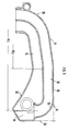
- Fig. 1 eine Ansicht der Brennkraftmaschine, teilweise im Schnitt, und von einer Stirnseite aus betrachtet,
- Fig. 2 einen Schnitt nach der Linie II-II der Fig. 1 in größerem Maßstab,
- Fig. 3 eine Ansicht in Pfeilrichtung A der Fig. 1,
- Fig. 4 einen Schnitt nach der Linie IV-IV der Fig. 1 in größerem Maßstab,
- Fig. 5 einen Schnitt nach der Linie V-V der Fig. 3 in größerem Maßstab.
- Eine mehrzylindrige Brennkraftmaschine 1 umfasst zwei Zylinderreihen 3, 4, deren Zylinder-Mittelachsen 5, 6 V-förmig zueinander angeordnet sind. Die Zylinderreihen 3, 4 weisen Zylinderköpfe 7 , 8 auf, die pro Zylinder mit zwei Einlaßventilen 9 ausgestattet sind, wobei die Einlaßventile 9 Gasströme zu einem Brennraum 10 steuern, die über zwei getrennte Ansaugkanäle 11, 12 dorthin gelangen. Die Ansaugkanäle 11, 12 sind Bestandteil des Zylinderkopfs 7 und liegen mit Eintrittsöffnungen 13, 14 auf einer gemeinsamen, parallel zu einer nicht gezeigten Kurbelwellen-Längsmittelachse verlaufenden Ebene B-B, die sich senkrecht zu einer Zylinderlängsmittelachse C-C erstreckt. Aus dem Zylinderkopf 7 seitlich herausgeführt sind Rohrstutzen 15, die Verlängerungen der Ansaugkanäle 11, 12 sind und an Rohrkörperstücke 16 einer Ansauganlage 17, und zwar unter Vermittlung muffenartiger, aus elastischem Werkstoff bestehender Verbindungselemente 18 angeschlossen sind.
- In den Rohrkörperstücken 16, die bogenförmig vom Zylinderkopf 7 weggeführt sind, sind getrennte Kanäle 19, 20 fortgeführt, die einen verschränkten Verlauf - siehe Mittelachsen 21, 22 der Kanäle 19, 20 in Fig. 4 - aufweisen. Der verschränkte Verlauf der Kanäle 19, 20 ist derart gestaltet, daß sie - in Querrichtung der Brennkraftmaschine 1 gesehen - in einer entfernt vom Zylinderkopf 7 oder 8 liegenden horizontalen Ebene D-D des Rohrkörperstücks 16 nebeneinanderliegen (Fig. 1 und 4). Anders ausgedrückt, die Kanäle 19, 20 haben einen unterschiedlichen Abstand zu den Zylinderköpfen 7, 8.
- Pro Zylinder ist ein Rohrkörperstück 16 vorgesehen, das sich zwischen dem Zylinderkopf 7 oder 8 und der Ebene D-D erstreckt und getrennt von einem Teil 23 der Ansauganlage 17 hergestellt ist. Das Rohrkörperstück 16 ist mit dem Teil 23 durch Schrauben 24, 25 miteinander verbunden. Außerdem ist es so gestaltet, daß es als Gleichteil für die verschiedenen Zylinder beider Zylinderreihen 3, 4 verwendbar ist.
- Die Ansauganlage 17 weist im Anschluß an die Rohrkörperstücke 16 einen Rohrbogen 26 auf, wodurch die getrennten Kanäle 19, 20 umgelenkt werden. Sie verlaufen folglich in einem sich quer zur Brennkraftmaschine erstreckenden Abschnitt 17 übereinanderliegend. Die Kanäle 19, 20 weisen zur Erhöhung des Drehmoments der Brennkraftmaschine 1 bei definierten Betriebsbedingungen unterschiedliche Längen - Kl₁ und Kl₂ - auf (Fig. 5). Dabei erstreckt sich der längere Kanal 20 entfernt von einer Haube 28, die den Zylinderkopf 8 überdeckt , d.h. bei üblicher Einbaulage einer Brennkraftmaschine (= Zylinder stehen aufrecht) erstreckt sich der Kanal 20 über dem Kanal 19. Übrigens ist der kürzere Kanal 19 - Kl₂ - bei niederer Drehzahl der Brennkraftmaschine geschlossen und bei höherer Drehzahl geöffnet, was durch eine Klappe 29 im Zylinderkopf 7 - Fig. 1 und 2 - bewerkstelligt wird. Beide Kanäle 19 und 20 münden in einen Verteilerraum 30, der in die Ansauganlage 17 integriert ist.
- Gemäß Fig. 1 ist die Brennkraftmaschine 1 quer in den Bug eines nicht näher dargestellten Personenwagens eingebaut, derart, daß die Zylinderreihen 3, 4 im gleichen Winkel zu einer senkrechten Querebene E-E des Personenwagens verlaufen, wobei in Fahrtrichtung F des Personenwagens gesehen die Zylinderreihe 3 vorne und die Zylinderreihe 4 hinten liegt. Die Ansauganlage 17 verläuft - in Querrichtung Brennkraftmaschine 1 gesehen - oberhalf der hinteren Zylinderreihe 4 um den Raum zwischen der Zylinderreihe 4 und einer Karosseriekontur 31 (Motorhaube) zu nutzen. Dabei verläuft die Ansauganlage 17 mit einer ersten Wand 32 abschnittsweise mit geringem Abstand G zur Haube 28. Über der ersten Wand 32 erstreckt sich eine zweite Wand 33, die einen durch Hilfslinien 34, 35 festgelegten dachförmigen Verlauf aufweist. Ein Wandabschnitt 36, der durch die Hilfslinie 34 definiert ist, verläuft benachbart der Karosseriekontur 31.
- Die Zylinderreihe 4 weist pro Zylinder eine Zündkerze auf - nicht dargestellt - die in einer Mittellängsebene H-H der Brennkraftmaschine angeordnet und über die Haube 28 zugänglich ist. Damit zum Prüfen oder Wechseln der Zündkerze die Ansauganlage 17 nicht demontiert werden muß, ist in dieser im Bereich der Zündkerze ein Durchgangskanal 37 vorgesehen.
- Darüber hinaus ist die Ansauganlage 17 schwingungsentkoppelt an der Brennkraftmaschine 1 gehalten. Hierzu ist sie einerseits mit den Verbindungselementen 18 mit der Brennkraftmaschine verbunden und andererseits stützt sie sich unter Vermittlung von elastischen Elementen 38, 39 and der besagten Maschine ab.
Claims (9)
Applications Claiming Priority (2)
| Application Number | Priority Date | Filing Date | Title |
|---|---|---|---|
| DE3641812 | 1986-12-06 | ||
| DE3641812A DE3641812C1 (de) | 1986-12-06 | 1986-12-06 | Ansauganlage fuer eine mehrzylindrige Brennkraftmaschine |
Publications (3)
| Publication Number | Publication Date |
|---|---|
| EP0270784A2 true EP0270784A2 (de) | 1988-06-15 |
| EP0270784A3 EP0270784A3 (en) | 1988-11-02 |
| EP0270784B1 EP0270784B1 (de) | 1991-08-07 |
Family
ID=6315658
Family Applications (1)
| Application Number | Title | Priority Date | Filing Date |
|---|---|---|---|
| EP87115409A Expired - Lifetime EP0270784B1 (de) | 1986-12-06 | 1987-10-21 | Ansauganlage für eine mehrzylindrige Brennkraftmaschine |
Country Status (5)
| Country | Link |
|---|---|
| US (1) | US4829942A (de) |
| EP (1) | EP0270784B1 (de) |
| JP (1) | JP2569089B2 (de) |
| DE (2) | DE3641812C1 (de) |
| ES (1) | ES2023873B3 (de) |
Cited By (2)
| Publication number | Priority date | Publication date | Assignee | Title |
|---|---|---|---|---|
| DE4244193A1 (de) * | 1992-12-24 | 1994-06-30 | Motoren Werke Mannheim Ag | Ansaugeinrichtung für eine Hubkolbenbrennkraftmaschine |
| DE102013017478A1 (de) | 2013-10-21 | 2015-04-23 | Audi Ag | Brennkraftmaschine sowie Verfahren zur Montage einer Brennkraftmaschine |
Families Citing this family (15)
| Publication number | Priority date | Publication date | Assignee | Title |
|---|---|---|---|---|
| DE3742057C1 (de) * | 1987-12-11 | 1988-09-22 | Porsche Ag | Ansauganlage fuer eine mehrzylindrige Brennkraftmaschine |
| US4932367A (en) * | 1988-07-20 | 1990-06-12 | Brunswick Corporation | Four-stroke V-engine with central exhaust and intake manifolds |
| KR940000129B1 (ko) * | 1988-07-29 | 1994-01-07 | 마쯔다 가부시기가이샤 | V형엔진의 흡기장치 |
| JP2517935Y2 (ja) * | 1988-11-25 | 1996-11-20 | マツダ株式会社 | V型エンジンのegr装置 |
| JP2772018B2 (ja) * | 1989-02-17 | 1998-07-02 | ヤマハ発動機株式会社 | エンジンの吸気装置 |
| JPH02215961A (ja) * | 1989-02-17 | 1990-08-28 | Nissan Motor Co Ltd | エンジンの吸気マニホールド装置 |
| JP2841465B2 (ja) * | 1989-04-28 | 1998-12-24 | スズキ株式会社 | 内燃機関の吸気装置 |
| US5261375A (en) * | 1989-11-06 | 1993-11-16 | General Motors Corporation | Fuel injection assembly for integrated induction system |
| US5003933A (en) * | 1989-11-06 | 1991-04-02 | General Motors Corporation | Integrated induction system |
| US5138983A (en) * | 1990-08-07 | 1992-08-18 | Siemens Automotive L. P. | Intake manifold/fuel rail |
| US5092284A (en) * | 1990-09-10 | 1992-03-03 | Yamaha Hatsudoki Kabushiki Kaisha | Control valve arrangement for engine |
| FI93139C (fi) * | 1991-11-11 | 1995-02-27 | Waertsilae Diesel Int | Kytkentäjärjestely paineväliaineita varten isoissa dieselmoottoreissa |
| US5273010A (en) * | 1992-08-28 | 1993-12-28 | General Motors Corporation | Intake manifold |
| US8151754B2 (en) * | 2008-09-16 | 2012-04-10 | Kawasaki Jukogyo Kabushiki Kaisha | Air-intake duct and air-intake structure |
| US10125729B1 (en) * | 2017-09-07 | 2018-11-13 | Indmar Products Company Inc. | Throttle body adapter for marine engine air intake |
Family Cites Families (13)
| Publication number | Priority date | Publication date | Assignee | Title |
|---|---|---|---|---|
| US2845912A (en) * | 1957-09-06 | 1958-08-05 | Gen Motors Corp | Induction system |
| US4066058A (en) * | 1976-05-12 | 1978-01-03 | Deere & Company | Vibration isolation system |
| DE2744039A1 (de) * | 1977-09-30 | 1979-04-05 | Bayerische Motoren Werke Ag | Elastische befestigungsanordnung einer saugrohranlage an einer mehrzylindrigen brennkraftmaschine |
| JPS6045751B2 (ja) * | 1978-05-17 | 1985-10-11 | ヤマハ発動機株式会社 | 燃料噴射式火花点火機関の吸気装置 |
| JPS595769B2 (ja) * | 1978-10-06 | 1984-02-07 | 本田技研工業株式会社 | 高出力型エンジン |
| JPS56101055A (en) * | 1980-01-18 | 1981-08-13 | Yamaha Motor Co Ltd | Engine for use in vehicle |
| JPS5770947A (en) * | 1980-10-21 | 1982-05-01 | Nippon Denso Co Ltd | Intake pipe device for internal combustion engine |
| DE54964T1 (de) * | 1980-12-22 | 1983-01-20 | Yamaha Motor Co., Ltd., Iwata, Shizuoka | Brennkraftmaschine mit mehreren einlassventilen. |
| JPS57110765A (en) * | 1980-12-27 | 1982-07-09 | Yamaha Motor Co Ltd | Intake unit for multiple intake valve type engine |
| JPS58119958A (ja) * | 1982-01-07 | 1983-07-16 | Yamaha Motor Co Ltd | 多気筒エンジンの吸気装置 |
| JPS5943923A (ja) * | 1982-09-03 | 1984-03-12 | Yamaha Motor Co Ltd | 多気筒エンジンの吸気装置 |
| JPH0670371B2 (ja) * | 1985-03-30 | 1994-09-07 | ヤマハ発動機株式会社 | 多気筒エンジンの吸気装置 |
| KR900000143B1 (ko) * | 1985-10-04 | 1990-01-20 | 마쯔다 가부시기가이샤 | V형 엔진의 흡기장치 |
-
1986
- 1986-12-06 DE DE3641812A patent/DE3641812C1/de not_active Expired
-
1987
- 1987-10-21 ES ES87115409T patent/ES2023873B3/es not_active Expired - Lifetime
- 1987-10-21 DE DE8787115409T patent/DE3772011D1/de not_active Expired - Lifetime
- 1987-10-21 EP EP87115409A patent/EP0270784B1/de not_active Expired - Lifetime
- 1987-12-03 US US07/128,419 patent/US4829942A/en not_active Expired - Fee Related
- 1987-12-04 JP JP30606087A patent/JP2569089B2/ja not_active Expired - Lifetime
Cited By (3)
| Publication number | Priority date | Publication date | Assignee | Title |
|---|---|---|---|---|
| DE4244193A1 (de) * | 1992-12-24 | 1994-06-30 | Motoren Werke Mannheim Ag | Ansaugeinrichtung für eine Hubkolbenbrennkraftmaschine |
| DE102013017478A1 (de) | 2013-10-21 | 2015-04-23 | Audi Ag | Brennkraftmaschine sowie Verfahren zur Montage einer Brennkraftmaschine |
| DE102013017478B4 (de) * | 2013-10-21 | 2015-06-25 | Audi Ag | Brennkraftmaschine sowie Verfahren zur Montage einer Brennkraftmaschine |
Also Published As
| Publication number | Publication date |
|---|---|
| EP0270784B1 (de) | 1991-08-07 |
| JP2569089B2 (ja) | 1997-01-08 |
| JPS63159660A (ja) | 1988-07-02 |
| US4829942A (en) | 1989-05-16 |
| EP0270784A3 (en) | 1988-11-02 |
| DE3772011D1 (de) | 1991-09-12 |
| ES2023873B3 (es) | 1992-02-16 |
| DE3641812C1 (de) | 1988-02-11 |
Similar Documents
| Publication | Publication Date | Title |
|---|---|---|
| DE3641812C1 (de) | Ansauganlage fuer eine mehrzylindrige Brennkraftmaschine | |
| DE3543443A1 (de) | Fremdgezuendete brennkraftmaschine | |
| DE4209155A1 (de) | Motorauspuffsystem | |
| DE3628230C2 (de) | Ansaugsystem für Verbrennungsmotoren | |
| DE69102857T2 (de) | Motorlufteinlasssystem. | |
| DE4030652A1 (de) | Verbrennungsmotor mit in v-form angeordneten zylinderbaenken | |
| DE1933271C3 (de) | Saugrohranordnung für Brennkraftmaschinen | |
| DE2331755C3 (de) | Saugrohranordnung an Hubkolben-Brennkraftmaschinen | |
| DE1296460B (de) | Zylinderkopf fuer Brennkraftmaschinen mit zwei Einlass- und zwei Auslassventilen je Zylinder | |
| DE2017877A1 (de) | Zylinderkopf | |
| DE3208478C2 (de) | Auspuffkrümmer für einen Vierzylinder-Reihenmotor | |
| DE4042415A1 (de) | Verbrennungsmotor mit in v-form angeordneten zylinderbaenken | |
| DE2507977C3 (de) | Ansaugkrümmer für Brennkraftmaschinen mit einer Verdampfungszone | |
| EP0897057A2 (de) | Vierventil-Zylinderkopf einer Brennkraftmaschine | |
| DE2616835C2 (de) | Ansaugleitungsystem für eine Mehrzylinder-Brennkraf tmaschine | |
| DE19940617A1 (de) | Ansaugkrümmer für Verbrennungsmotoren | |
| EP1178189B1 (de) | Sauganlage | |
| DE3116802C2 (de) | Vierventil-Zylinderkopf für einen Viertaktmotor | |
| DE2736466C3 (de) | Saugrohranlage fur Brennkraftmaschinen | |
| DE10125903B4 (de) | Ansaugeinrichtung eines Mehrzylinder-Verbrennungsmotors | |
| DE102021110255B4 (de) | Motoreinlassvorrichtung | |
| DE4126428C2 (de) | Saugrohranlage | |
| EP0113441B2 (de) | Luftansauganlage für Brennkraftmaschinen, insbesondere Einspritz-Brennkraftmaschinen | |
| AT254621B (de) | Brennkraftmaschine mit in V-Form angeordneten Zylinderreihen | |
| DE19720490A1 (de) | Zylinderkopf für Mehrzylinder-Verbrennungsmotoren mit Kraftstoffdirekteinspritzung |
Legal Events
| Date | Code | Title | Description |
|---|---|---|---|
| PUAI | Public reference made under article 153(3) epc to a published international application that has entered the european phase |
Free format text: ORIGINAL CODE: 0009012 |
|
| AK | Designated contracting states |
Kind code of ref document: A2 Designated state(s): DE ES FR GB IT SE |
|
| PUAL | Search report despatched |
Free format text: ORIGINAL CODE: 0009013 |
|
| AK | Designated contracting states |
Kind code of ref document: A3 Designated state(s): DE ES FR GB IT SE |
|
| 17P | Request for examination filed |
Effective date: 19890301 |
|
| 17Q | First examination report despatched |
Effective date: 19891117 |
|
| ITF | It: translation for a ep patent filed | ||
| GRAA | (expected) grant |
Free format text: ORIGINAL CODE: 0009210 |
|
| AK | Designated contracting states |
Kind code of ref document: B1 Designated state(s): DE ES FR GB IT SE |
|
| GBT | Gb: translation of ep patent filed (gb section 77(6)(a)/1977) | ||
| REF | Corresponds to: |
Ref document number: 3772011 Country of ref document: DE Date of ref document: 19910912 |
|
| ET | Fr: translation filed | ||
| REG | Reference to a national code |
Ref country code: ES Ref legal event code: FG2A Ref document number: 2023873 Country of ref document: ES Kind code of ref document: B3 |
|
| PLBE | No opposition filed within time limit |
Free format text: ORIGINAL CODE: 0009261 |
|
| STAA | Information on the status of an ep patent application or granted ep patent |
Free format text: STATUS: NO OPPOSITION FILED WITHIN TIME LIMIT |
|
| 26N | No opposition filed | ||
| PGFP | Annual fee paid to national office [announced via postgrant information from national office to epo] |
Ref country code: SE Payment date: 19931005 Year of fee payment: 7 |
|
| PGFP | Annual fee paid to national office [announced via postgrant information from national office to epo] |
Ref country code: ES Payment date: 19931019 Year of fee payment: 7 |
|
| PG25 | Lapsed in a contracting state [announced via postgrant information from national office to epo] |
Ref country code: SE Effective date: 19941022 Ref country code: ES Free format text: LAPSE BECAUSE OF NON-PAYMENT OF DUE FEES Effective date: 19941022 |
|
| EAL | Se: european patent in force in sweden |
Ref document number: 87115409.2 |
|
| EUG | Se: european patent has lapsed |
Ref document number: 87115409.2 |
|
| PGFP | Annual fee paid to national office [announced via postgrant information from national office to epo] |
Ref country code: GB Payment date: 19961015 Year of fee payment: 10 |
|
| PGFP | Annual fee paid to national office [announced via postgrant information from national office to epo] |
Ref country code: DE Payment date: 19961022 Year of fee payment: 10 |
|
| PGFP | Annual fee paid to national office [announced via postgrant information from national office to epo] |
Ref country code: FR Payment date: 19961028 Year of fee payment: 10 |
|
| PG25 | Lapsed in a contracting state [announced via postgrant information from national office to epo] |
Ref country code: GB Free format text: LAPSE BECAUSE OF NON-PAYMENT OF DUE FEES Effective date: 19971021 |
|
| PG25 | Lapsed in a contracting state [announced via postgrant information from national office to epo] |
Ref country code: FR Free format text: THE PATENT HAS BEEN ANNULLED BY A DECISION OF A NATIONAL AUTHORITY Effective date: 19971031 |
|
| GBPC | Gb: european patent ceased through non-payment of renewal fee |
Effective date: 19971021 |
|
| PG25 | Lapsed in a contracting state [announced via postgrant information from national office to epo] |
Ref country code: DE Free format text: LAPSE BECAUSE OF NON-PAYMENT OF DUE FEES Effective date: 19980701 |
|
| REG | Reference to a national code |
Ref country code: FR Ref legal event code: ST |
|
| REG | Reference to a national code |
Ref country code: ES Ref legal event code: FD2A Effective date: 19951113 |
|
| PG25 | Lapsed in a contracting state [announced via postgrant information from national office to epo] |
Ref country code: IT Free format text: LAPSE BECAUSE OF NON-PAYMENT OF DUE FEES;WARNING: LAPSES OF ITALIAN PATENTS WITH EFFECTIVE DATE BEFORE 2007 MAY HAVE OCCURRED AT ANY TIME BEFORE 2007. THE CORRECT EFFECTIVE DATE MAY BE DIFFERENT FROM THE ONE RECORDED. Effective date: 20051021 |