EP0264925A1 - Procédé pour charger et décharger un récipient creux, tel qu'un silo, conteneur ou semblable sur/d'un véhicule à l'aide d'un dispositif interchangeable, dispositif interchangeable pour la réalisation de ce procédé ainsi que récipient utilisé pour la réalisation de ce procédé - Google Patents
Procédé pour charger et décharger un récipient creux, tel qu'un silo, conteneur ou semblable sur/d'un véhicule à l'aide d'un dispositif interchangeable, dispositif interchangeable pour la réalisation de ce procédé ainsi que récipient utilisé pour la réalisation de ce procédé Download PDFInfo
- Publication number
- EP0264925A1 EP0264925A1 EP87115382A EP87115382A EP0264925A1 EP 0264925 A1 EP0264925 A1 EP 0264925A1 EP 87115382 A EP87115382 A EP 87115382A EP 87115382 A EP87115382 A EP 87115382A EP 0264925 A1 EP0264925 A1 EP 0264925A1
- Authority
- EP
- European Patent Office
- Prior art keywords
- container
- vehicle
- tilting frame
- vessel
- frame
- Prior art date
- Legal status (The legal status is an assumption and is not a legal conclusion. Google has not performed a legal analysis and makes no representation as to the accuracy of the status listed.)
- Granted
Links
- 238000000034 method Methods 0.000 title claims abstract description 27
- 230000008569 process Effects 0.000 title description 9
- 238000000151 deposition Methods 0.000 claims description 6
- 238000004904 shortening Methods 0.000 claims description 3
- 230000008859 change Effects 0.000 description 9
- 230000008901 benefit Effects 0.000 description 5
- 238000009434 installation Methods 0.000 description 5
- 238000005096 rolling process Methods 0.000 description 5
- 238000006073 displacement reaction Methods 0.000 description 3
- 238000013459 approach Methods 0.000 description 2
- 238000013461 design Methods 0.000 description 2
- 239000010791 domestic waste Substances 0.000 description 2
- 230000009471 action Effects 0.000 description 1
- 238000010276 construction Methods 0.000 description 1
- 230000001419 dependent effect Effects 0.000 description 1
- 238000011161 development Methods 0.000 description 1
- 230000005484 gravity Effects 0.000 description 1
- 239000000463 material Substances 0.000 description 1
- 210000000056 organ Anatomy 0.000 description 1
- 230000003014 reinforcing effect Effects 0.000 description 1
- 230000000284 resting effect Effects 0.000 description 1
- 238000012546 transfer Methods 0.000 description 1
Images


Classifications
-
- B—PERFORMING OPERATIONS; TRANSPORTING
- B60—VEHICLES IN GENERAL
- B60P—VEHICLES ADAPTED FOR LOAD TRANSPORTATION OR TO TRANSPORT, TO CARRY, OR TO COMPRISE SPECIAL LOADS OR OBJECTS
- B60P1/00—Vehicles predominantly for transporting loads and modified to facilitate loading, consolidating the load, or unloading
- B60P1/64—Vehicles predominantly for transporting loads and modified to facilitate loading, consolidating the load, or unloading the load supporting or containing element being readily removable
-
- Y—GENERAL TAGGING OF NEW TECHNOLOGICAL DEVELOPMENTS; GENERAL TAGGING OF CROSS-SECTIONAL TECHNOLOGIES SPANNING OVER SEVERAL SECTIONS OF THE IPC; TECHNICAL SUBJECTS COVERED BY FORMER USPC CROSS-REFERENCE ART COLLECTIONS [XRACs] AND DIGESTS
- Y10—TECHNICAL SUBJECTS COVERED BY FORMER USPC
- Y10S—TECHNICAL SUBJECTS COVERED BY FORMER USPC CROSS-REFERENCE ART COLLECTIONS [XRACs] AND DIGESTS
- Y10S414/00—Material or article handling
- Y10S414/132—Vehicle-carried storage member, e.g. portable silo and means for erecting member from attitude during transport to position of intended use
Definitions
- the invention relates to a method for receiving and depositing a hollow container, such as a silo, container or the like, on or from a vehicle with an interchangeable device which has a tilting frame which is articulated on the rear of the vehicle chassis and movable by means of a tilt cylinder supported on the chassis and which has a slide which can be displaced on the tilting frame by means of associated actuating members and which is equipped with a stop element which can be brought into engagement with the associated fitting on the container.
- a hollow container such as a silo, container or the like
- Vehicles equipped with an exchange device are special vehicles that are able to pick up or set down and transport empty or filled swap bodies.
- silo containers are vertical at the installation site. However, they must be transported by vehicle to the installation site or away from the installation site in a lying position. The picking up and setting down of such silos thus requires changing devices which can transfer a container to be set up, in particular a silo, from the lying position into the vertically standing position.
- special construction measures must be taken so that both the vehicle and the changer are able to handle the considerable weights of filled containers, especially silos, during opening mastery of taking and weaning.
- Vehicles with an interchangeable device are therefore equipped with extendable, fold-out or in some other way stand-by supports, in particular in the area of the rear of the vehicle, which are brought into a support position prior to the pick-up or drop-down process, in which they place the vehicle on the floor or on support the road surface.
- the supports mean a relatively high loss of payload and that, moreover, the stability of the vehicle, for example when a support leg sags, as can occur in unfavorable ground conditions, is problematic.
- the picking up and setting down of heavy containers, especially silos, is also difficult because the operation of the changing device requires both a control of the tilting movement of the tilting frame and at the same time a control of the displacement movement of the link of the tilting frame.
- the controls are carried out manually, since each container or each silo requires customized operation due to its design or dimensions.
- the safety when picking up and setting down containers, in particular silos, is therefore highly dependent on the care and skill of the person who has to operate the change device or the vehicle with the change device.
- the object of the invention is to make it easier to pick up and set down a container, in particular a silo, on or from a vehicle with a changing device.
- This object has been achieved according to the invention by a method in which, for setting down the container, the backdrop is retracted until the rear end of the container protrudes beyond the rear of the vehicle by a predetermined amount, the tilting frame is then tilted until the lower area at the rear The end of the container rests on the road surface, the actuator supply organs of the backdrop are switched to freewheeling and then, if the vehicle brakes are released, the tilting frame is tilted further until the container stands upright on its rear end and the stop element and fitting can be disengaged.
- the container in particular a silo, which has been transported lying on the changing device of the vehicle, is first pushed backwards by controlled displacement of the link to a specific position.
- the end of the container, silo or container presses onto the floor. This shifts the weight of the container to its rear end and stabilizes it by resting it on the road surface or the floor.
- the actuating member of the link is switched to freewheeling, with the essential advantage that the tilting frame can be tilted up to the vertical in a continuous tilting process.
- the backdrop remains connected to the silo, so that it can slide out further due to its freewheeling action or is automatically pulled out.
- the stop element can be released from the fitting of the container or silo.
- the process described is reversed.
- the vehicle drives up to the standing silo and swivels its tipping frame into the vertical and pushes the backdrop of the tipping frame until the stop element is fitted with the Silos can be brought into engagement.
- the actuating member of the backdrop is switched to freewheel again and the recording process can be carried out by folding in the tilting frame until the container has reached the approximately 45 ° position again and is then finally placed on the vehicle .
- the container or the silo swivels around the support points with which its rear end is supported on the road surface or the ground.
- this support position is reached when the tilting frame is tilted by approximately 45 °.
- the brakes of the vehicle equipped with the changer must be released so that the swivel axis around which the tilting frame moves during its tilting movement of the positive guidance on a circular path around the support point of the silo can follow the ground by the vehicle rolling on the road surface or the ground.
- the method according to the invention is particularly advantageously developed for receiving a standing container so that, after the stop element has latched into the container fitting, the rear of the vehicle on the standing container is pulled up by a predetermined amount.
- the rear of the vehicle can be pulled up, for example, by shortening the length of the tipping frame by pulling the link accordingly into the tipping frame by means of its actuating member.
- the rear of the vehicle can be pulled up until the rear wheels of the vehicle are clear of the ground.
- This measure of pulling up the rear of the vehicle has the advantage that the weight of the vehicle comes into play fully as a counterweight via the tilting hydraulics and thus also takes over a vertically standing container, in particular a silo can be done by relatively light vehicles.
- the tipping frame After lifting the rear of the vehicle, the tipping frame can be swiveled back until the wheels of the vehicle are level with the rear end of the silo, here the road surface.
- the actuator for the backdrop is then switched to freewheeling until the container, in particular the silo, is received by the vehicle.
- the method according to the invention for picking up and depositing containers, in particular silos also has the advantage that silos or containers that have appropriate emptying or filling openings on one end face on which they are to be positioned and thus have corresponding openings in the floor are to be set up precisely, can be set up precisely because the end of the container can already be snapped into adapters or similar guide devices before the final installation has taken place. This is possible because the rolling movement of the vehicle automatically causes any necessary readjustments during the tilting movement.
- actuators for a backdrop that changes the length of the tilting frame are switched to freewheeling
- Change devices of the type in question are mostly equipped with hydraulics.
- a particularly advantageous embodiment of a changing device for carrying out the method according to the invention, for which independent protection is also claimed, is characterized in that the setting is designed as a simple sliding frame, the free end of which has the stop element.
- the L-shaped backdrop is therefore missing.
- the changeover device is therefore considerably lighter, which results in a further increase in the payload.
- Such a changing device is particularly advantageously also suitable for vehicles which are equipped with a press into which bulk goods to be picked up, for example domestic waste, can be input. The press then places the compressed materials in a container that is also picked up by the vehicle using an exchange device. As soon as the container is filled, it can be put down with the change unit and the vehicle can pick up a new, empty change container.
- the press is mounted directly behind the driver's cab, the outlet of the press extending into the container which is placed directly on the press and carried on the vehicle with the changer.
- the change device according to the invention in which the backdrop is designed as a simple sliding frame with which the tilting frame can be lengthened or shortened, the advantageous method of picking up and setting down containers can also be used in vehicles with a press.
- the changer is advantageously light in weight and, as already described, can nevertheless safely and easily pick up and set down heavy containers.
- the actuator for the link is at least one working cylinder, for example a double-acting working cylinder.
- an actuatable is order provided by which such a cylinder can be brought into the floating position. This can be achieved, for example, by inserting a bypass into the pressure medium delivery lines of the working cylinder for shifting the link, which can be activated by means of shut-off elements.
- the changer is characterized in that the stop element has an actuatable locking member.
- the locking member allows the mutual engagement of the stop element of the link and the fitting of the container to be maintained even when the link is retracted in order to pull up the rear of the vehicle on a standing container to be accommodated.
- the locking member can e.g. a simple, manually or pneumatically, hydraulically, etc. operated locking bolt that can lock a hook mouth of a stop element designed as a hook.
- such a securing is implemented in the changing device according to the invention in that the tilting frame has guide members located in its side area and engaging in guide elements on the container.
- Each guide member is particularly advantageously designed as a folding roller mounted on the tilting frame, which projects into a guide rail of the container has standing rolling body, which is equipped with a radially projecting wheel rim in order to also perform lateral guide functions on the outside of the guide rail.
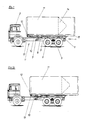
- a tipping frame 5 is articulated on the chassis at the rear in the area of the vehicle rear 4.
- the tilting frame can be pivoted about the axis 6 indicated here.
- the front free end of the tipping frame 5 is designed as a guide for a link 10.
- the setting 10 can be pushed out of the tilting frame by means of an actuating member, for example a working cylinder, not shown here, in order to lengthen it or retracted in order to shorten the tilting frame.
- the container has a fitting 12 with which it is latched into a stop element 13 at the free end of the link 10.
- the container 11 can thus be pulled on the vehicle towards the driver's cab 2 or, when the tipping frame is shortened by pushing in the link 10, pushed back over the rear of the vehicle 4 until the feet on rear end 15 of the container, which hold the bottom 14 equipped with an outlet when the container is standing at a free height above the standing surface, to protrude a predetermined amount beyond the rear of the vehicle.
- Fig. 1a The total weight of the container has shifted towards the rear axle of the vehicle.
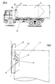
- the tilting cylinder 8 is extended in a next process step, so that the lower rear end 15 of the container lies on the ground, here the road surface 16, as shown.
- the center of gravity of the container, and thus its total weight, is still at this tilted position of approximately 45 ° approximately above the rear axle of the vehicle, so that the support points of the tilted container on the road surface and the rear wheels of the vehicle provide a multi-point support for the tilted container form, which is relatively safe in this position.
- the actuator of the backdrop here a double-acting cylinder
- the free-running position which can be done in the cylinder by appropriate bypasses in the pressure medium feeds.
- the working cylinder moving the backdrop is thereby brought into a so-called "floating position", whereby the backdrop can move freely when the tilt cylinder 8 moves the tilting frame and thus also the container from the 45 ° position according to FIG. 1b into the vertical position according to FIG 1c transferred, the different tilting positions indicated in FIG. 1c being continuously run through.
- the container pivots about an axis that lies in the plane of the road surface.
- the axis 6, about which the tilting frame pivots with respect to the chassis can move along when the vehicle brakes are released; because when the container is erected, the vehicle rolls backwards and approaches the container's point of support on the road surface.
- the process is reversed.
- the vehicle approaches the standing container.
- the tilting frame is brought into a vertical position until it lies against the standing container and its stop element is latched into the fitting 12 of the container. This position corresponds to the vertical position of the container in Fig. 1c.
- the vehicle rear 4 is pulled up on the container 11 until the wheels 17 of the vehicle are more or less lifted from the road surface 16, as shown in Fig. 1d.
- the tilt cylinder 8 here a multi-stage cylinder, is extended.
- the tilt cylinder is retracted until the rear wheels 17 of the vehicle touch the ground again.
- the vehicle weight serves as a counterweight for tilting the container 11. This means that even filled and thus relative heavy containers 11 can be easily accommodated with relatively light vehicles.
- FIG. 2 shows a vehicle with a receptacle 11.
- the change device of the vehicle here again consists of a tilting frame corresponding to FIG. 1 and a link that lengthens or shortens the tilting frame, the link being, however, designed as an L-shaped arm, one of which is an L- Leg 18 is inserted and pushed out in the tilting frame, while the other approximately perpendicular L-leg 19 has at its upper free end the stop element designed here as a hook 20, which can be latched into a corresponding fitting on the end face 21 of the container.
- an abutment element for example as shown in FIG.
- a suitable stop element 13 is shown in Fig. 3, which shows a schematic side view of the upper part of a container 11 clipped into the changer.
- the stop element 13 comprises a hook 13 'projecting from the link 10, which can grip a fitting 12 designed as a bolt with the hook mouth.
- an actuatable locking member is arranged, which is designed as the hook jaw locking pivot bolt 13 ⁇ .
- the swivel arm gel can be moved electromagnetically, pneumatically or hydraulically.
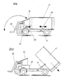
- Fig. 4 shows the schematic side view of a vehicle with which e.g. Household waste can be collected.
- the front of the vehicle which is equipped with the driver's cab, has a loading device 22 known per se. Behind the driver's cab, a press 23, which is only indicated here, is mounted, into the input shaft 24 of which the goods received with the loading device 22 can be entered.
- the press conveys in the direction of arrow 25 into a container 11 ⁇ accommodated on the vehicle, which has a corresponding opening on its end facing the press, through which the outlet opening of the press extends into the container.
- the vehicle is equipped with an exchange device for receiving and depositing the container 11 ⁇ , of which only the tilt cylinder 8 is indicated here.
- the slide-in and slide-out backdrop of the tilting frame has the advantage that the container 11 still on the vehicle, as soon as it is to be set down, can be pulled back from the mouth of the press or an empty container that has just been picked up against the Press can be advanced, as was shown by the double arrow 26.
- the tilting cylinder 8 is extended (FIG. 5), the setting down process taking place as described above.
- the filled container can be placed standing on one end and stored until further transport, as shown in FIG. 6.
- Standing containers can of course also be accommodated, in which case the pivoting movement of the tilting frame is reversed.
- Picking up and setting down is indicated in FIG. 5 by the double arrow 27.
- each guide element 29 is a profile rail, for example a U-profile or I-profile, which is arranged on the container so that the container rests on the tilting frame with two parallel profile rails.
- Guide elements 28 engaging in the guide elements 29 are arranged on the tilting frame.
- Each guide member comprises a folding roller 30 which is mounted on the free end of a folding lever 31.
- the folding lever 31 is articulated on the tilting frame 5. The foldability of the folding roller enables the guide members 28 to be brought into or out of engagement with the guide elements 29 of the container 11.
- FIG. 8 shows a sectional view of a guide element, here an I-profile, in which a guide member 28 designed as a folding roller 30 engages.
- the foldability is illustrated by the double arrow 31.
- Fig. 8 shows that each folding roller 30 consists of a rolling body 32 which engages between the T-flanges of the I-profile and can roll on a reinforcing rail 33 of the lower T-flange 34.
- the rolling element has a protruding wheel rim 35.
Landscapes
- Engineering & Computer Science (AREA)
- Transportation (AREA)
- Mechanical Engineering (AREA)
- Loading Or Unloading Of Vehicles (AREA)
- Handcart (AREA)
- Filling Or Emptying Of Bunkers, Hoppers, And Tanks (AREA)
Priority Applications (1)
| Application Number | Priority Date | Filing Date | Title |
|---|---|---|---|
| AT87115382T ATE59609T1 (de) | 1986-10-23 | 1987-10-21 | Verfahren zum aufnehmen und absetzen eines hohl- behaelters, wie silo, container oder dergleichen, auf bzw. von einem fahrzeug mit wechselgeraet, wechselgeraet zur durchfuehrung des verfahrens sowie bei der durchfuehrung des verfahrens verwendbarer behaelter. |
Applications Claiming Priority (2)
| Application Number | Priority Date | Filing Date | Title |
|---|---|---|---|
| DE19863636037 DE3636037A1 (de) | 1986-10-23 | 1986-10-23 | Verfahren zum aufnehmen und absetzen eines hohl-behaelters, wie silo, container oder dergleichen, auf bzw. von einem fahrzeug mit wechselgeraet, wechselgeraet zur durchfuehrung des verfahrens sowie bei der durchfuehrung des verfahrens verwendbarer behaelter |
| DE3636037 | 1986-10-23 |
Publications (3)
| Publication Number | Publication Date |
|---|---|
| EP0264925A1 true EP0264925A1 (fr) | 1988-04-27 |
| EP0264925B1 EP0264925B1 (fr) | 1991-01-02 |
| EP0264925B2 EP0264925B2 (fr) | 1994-04-06 |
Family
ID=6312291
Family Applications (1)
| Application Number | Title | Priority Date | Filing Date |
|---|---|---|---|
| EP87115382A Expired - Lifetime EP0264925B2 (fr) | 1986-10-23 | 1987-10-21 | Procédé pour charger et décharger un récipient creux, tel qu'un silo, conteneur ou semblable sur/d'un véhicule à l'aide d'un dispositif interchangeable, dispositif interchangeable pour la réalisation de ce procédé ainsi que récipient utilisé pour la réalisation de ce procédé |
Country Status (6)
| Country | Link |
|---|---|
| US (1) | US5082416A (fr) |
| EP (1) | EP0264925B2 (fr) |
| AT (1) | ATE59609T1 (fr) |
| DE (2) | DE3636037A1 (fr) |
| ES (1) | ES2020669T5 (fr) |
| GR (1) | GR3001629T3 (fr) |
Cited By (6)
| Publication number | Priority date | Publication date | Assignee | Title |
|---|---|---|---|---|
| US5044861A (en) * | 1988-06-22 | 1991-09-03 | Edelhoff Polytechnik Gmbh & Co. | Garbage-collecting truck having a replaceable container which is reciprocably mounted on a tiltable frame |
| WO1996022930A1 (fr) * | 1995-01-23 | 1996-08-01 | Multilift Oy | Procede de manutention des detritus, systeme de manutention des detritus et conteneur a detritus |
| WO2001005692A1 (fr) * | 1999-07-16 | 2001-01-25 | Taylors Engineering (Blenheim) Limited | Dispositif de vidage d'un receptacle |
| CN105775777A (zh) * | 2016-05-16 | 2016-07-20 | 徐州徐工环境技术有限公司 | 一种垃圾箱举升倾倒机构 |
| CN109850589A (zh) * | 2018-12-31 | 2019-06-07 | 徐州易尚饰家装饰工程有限责任公司 | 一种合金冶炼合金粉添加计量平台 |
| CN114044333A (zh) * | 2021-11-30 | 2022-02-15 | 伯朗特机器人股份有限公司 | 一种用于伸缩膜的翻转装置 |
Families Citing this family (23)
| Publication number | Priority date | Publication date | Assignee | Title |
|---|---|---|---|---|
| DE3809760A1 (de) * | 1988-03-23 | 1989-10-05 | Bock Norman | Auf einem lastkraftwagen angeordnetes wechselgeraet zum aufnehmen und absetzen von behaeltern |
| DE4013267A1 (de) * | 1990-04-26 | 1991-10-31 | Bock Norman | Wechselgeraet zum auf- und abladen sowie zum transport von wechselbehaeltern, insbesondere transportsilos |
| DE4412680A1 (de) * | 1994-04-13 | 1995-10-19 | Kirchhoff Heine Strassenbauges | Schüttgutbehälter-System |
| US5562390A (en) * | 1995-01-24 | 1996-10-08 | Mcneilus Truck And Manufacturing, Inc. | Detachable truck body and handling mechanism |
| US7029226B2 (en) * | 1999-06-07 | 2006-04-18 | Walsh Alan J | Cargo carrying deck for the tractor of a semitrailer truck |
| DE10009821A1 (de) * | 2000-03-01 | 2001-09-20 | Deutsche Bahn Ag | Containeraufbau |
| AU2003213129A1 (en) * | 2002-04-15 | 2003-11-03 | Boasso America Corporation (A Louisiana Corporation) | Method and apparatus for supplying bulk product to an end user |
| DE10250678A1 (de) * | 2002-05-08 | 2003-11-27 | Hueffermann Fahrzeugtech Gmbh | Vorrichtung zum Bewegen eines Wechselbehälters |
| US6733027B2 (en) | 2002-06-19 | 2004-05-11 | Delaware Capital Formation, Inc. | Detachable truck body/semi trailer |
| US7192239B2 (en) * | 2004-09-23 | 2007-03-20 | Automated Waste Equipment Co., Inc. | Apparatus for dual stage loading of a container upon a roll-off vehicle |
| US20060062660A1 (en) * | 2004-09-23 | 2006-03-23 | Lazar Marmur | Apparatus for loading and unloading of a container upon a roll-off vehicle including a movable frame section |
| US8029228B2 (en) * | 2007-03-09 | 2011-10-04 | Omaha Standard, Inc. | Cable hoisting apparatus |
| US20100239404A1 (en) * | 2009-03-23 | 2010-09-23 | Bert Joseph Blanchard | Storage and deployment system |
| WO2012126050A1 (fr) * | 2011-03-23 | 2012-09-27 | O'keefe Robert Trevor | Système et procédé de chargement et de déchargement de conteneurs |
| US10836568B2 (en) | 2011-10-24 | 2020-11-17 | Solaris Oilfield Site Services Operating Llc | Blender hopper control system for multi-component granular compositions |
| MX348588B (es) | 2011-10-24 | 2017-06-20 | Solaris Oilfield Site Services Operating Llc | Sistema de silo para arena de fractura y métodos para el despliegue y retracción del mismo. |
| US10300830B2 (en) | 2011-10-24 | 2019-05-28 | Solaris Oilfield Site Services Operating Llc | Storage and blending system for multi-component granular compositions |
| CN102923426B (zh) * | 2012-11-19 | 2015-04-15 | 大连交通大学 | 用于垂直式垃圾中转站的垃圾容器转运车架 |
| US11091317B2 (en) | 2014-05-06 | 2021-08-17 | Jwf Industries, Inc. | Vertical fluid storage tank with connecting ports |
| US10202236B2 (en) | 2014-05-06 | 2019-02-12 | JWF Industries | Portable vertical fluid storage tank |
| USD819778S1 (en) | 2014-05-08 | 2018-06-05 | JWF Industries | Vertical fluid storage tank |
| US20160230934A1 (en) * | 2015-02-05 | 2016-08-11 | Fb Industries Inc. | Method for Storing a Pressurized Liquid or Gas in a Portable Storage Tank |
| CN114044332B (zh) * | 2021-11-30 | 2023-08-22 | 伯朗特机器人股份有限公司 | 用于可储料伸缩膜横向转变为竖向定位的设备 |
Citations (4)
| Publication number | Priority date | Publication date | Assignee | Title |
|---|---|---|---|---|
| US2606676A (en) * | 1947-01-03 | 1952-08-12 | George R Dempster | Transporting equipment for vehicles |
| DE8019121U1 (de) * | 1980-07-16 | 1982-02-25 | Paul Nutzfahrzeug KG, 8390 Passau | Kombinierte wechsel-kipp-einrichtung fuer nutzfahrzeugaufbauten |
| DE3312508A1 (de) * | 1983-04-07 | 1984-10-11 | Franz Xaver Meiller Fahrzeug- und Maschinenfabrik - GmbH & Co KG, 8000 München | Zusatzvorrichtung fuer einen abrollkipper |
| DE3329412A1 (de) * | 1983-08-13 | 1985-02-21 | Maschinen- und Apparatebau August Tepe GmbH, 2848 Vechta | Vorrichtung zum auf- und abladen von behaeltern fuer fahrzeuge mit einem als ladeplattform ausgebildeten chassis |
Family Cites Families (15)
| Publication number | Priority date | Publication date | Assignee | Title |
|---|---|---|---|---|
| US3272546A (en) * | 1964-12-03 | 1966-09-13 | Tri City Ind Service Inc | Push-pull device for containers |
| US3355043A (en) * | 1965-10-20 | 1967-11-28 | Int Harvester Co | Truck and body connection means |
| US3643824A (en) * | 1970-04-08 | 1972-02-22 | Smithpac Canada Ltd | Automatic packer cycle for refuse-carrying apparatus |
| US3819075A (en) * | 1970-10-01 | 1974-06-25 | Saphem | Device for loading a skip on to a vehicle |
| US3812988A (en) * | 1972-12-06 | 1974-05-28 | J Pyle | Boat transporting, launching and retrieving trailer |
| US3985254A (en) * | 1973-07-25 | 1976-10-12 | Societe Mobiliere Industrielle | System and method for loading and unloading a storage apparatus from a vehicle |
| US3892323A (en) * | 1974-04-24 | 1975-07-01 | Bennes Marrel | Container-handling device for a self-loading vehicle |
| US4091946A (en) * | 1976-03-08 | 1978-05-30 | Kraeft Robert W | Truck-mounted cable reel handling apparatus |
| JPS6045A (ja) * | 1983-06-15 | 1985-01-05 | Shimadzu Corp | 表面分析装置 |
| NL8400354A (nl) * | 1984-02-04 | 1985-09-02 | Multilift Bv | Langwerpige, tijdens gebruik rechtopstaande transportabele eenheid. |
| DE3416643A1 (de) * | 1984-05-05 | 1985-11-07 | P.F.T. Putz- und Fördertechnik GmbH, 8715 Iphofen | Behaelter, insbesondere fuer baustoff, und zugehoeriges transportfahrzeug |
| DE3420058A1 (de) * | 1984-05-29 | 1985-12-05 | Edelhoff Polytechnik GmbH & Co, 5860 Iserlohn | Motorgetriebenes muellsammelfahrzeug mit als wechselbehaelter ausgebildeten containern |
| DE3610263A1 (de) * | 1985-04-02 | 1986-10-02 | Siegfried 8000 München Seidl | Transporteinrichtung |
| US4626166A (en) * | 1985-11-06 | 1986-12-02 | Jolly Arthur E | Method for the placement of a trailer-mounted sand hopper |
| US4840532A (en) * | 1986-03-03 | 1989-06-20 | Galbreath Incorporated | Roll-off hoist for variable positioning of containers |
-
1986
- 1986-10-23 DE DE19863636037 patent/DE3636037A1/de not_active Ceased
-
1987
- 1987-10-21 DE DE8787115382T patent/DE3766933D1/de not_active Expired - Fee Related
- 1987-10-21 EP EP87115382A patent/EP0264925B2/fr not_active Expired - Lifetime
- 1987-10-21 ES ES87115382T patent/ES2020669T5/es not_active Expired - Lifetime
- 1987-10-21 AT AT87115382T patent/ATE59609T1/de not_active IP Right Cessation
-
1990
- 1990-08-24 US US07/574,535 patent/US5082416A/en not_active Expired - Fee Related
-
1991
- 1991-03-20 GR GR91400352T patent/GR3001629T3/el unknown
Patent Citations (4)
| Publication number | Priority date | Publication date | Assignee | Title |
|---|---|---|---|---|
| US2606676A (en) * | 1947-01-03 | 1952-08-12 | George R Dempster | Transporting equipment for vehicles |
| DE8019121U1 (de) * | 1980-07-16 | 1982-02-25 | Paul Nutzfahrzeug KG, 8390 Passau | Kombinierte wechsel-kipp-einrichtung fuer nutzfahrzeugaufbauten |
| DE3312508A1 (de) * | 1983-04-07 | 1984-10-11 | Franz Xaver Meiller Fahrzeug- und Maschinenfabrik - GmbH & Co KG, 8000 München | Zusatzvorrichtung fuer einen abrollkipper |
| DE3329412A1 (de) * | 1983-08-13 | 1985-02-21 | Maschinen- und Apparatebau August Tepe GmbH, 2848 Vechta | Vorrichtung zum auf- und abladen von behaeltern fuer fahrzeuge mit einem als ladeplattform ausgebildeten chassis |
Cited By (7)
| Publication number | Priority date | Publication date | Assignee | Title |
|---|---|---|---|---|
| US5044861A (en) * | 1988-06-22 | 1991-09-03 | Edelhoff Polytechnik Gmbh & Co. | Garbage-collecting truck having a replaceable container which is reciprocably mounted on a tiltable frame |
| WO1996022930A1 (fr) * | 1995-01-23 | 1996-08-01 | Multilift Oy | Procede de manutention des detritus, systeme de manutention des detritus et conteneur a detritus |
| WO2001005692A1 (fr) * | 1999-07-16 | 2001-01-25 | Taylors Engineering (Blenheim) Limited | Dispositif de vidage d'un receptacle |
| CN105775777A (zh) * | 2016-05-16 | 2016-07-20 | 徐州徐工环境技术有限公司 | 一种垃圾箱举升倾倒机构 |
| CN109850589A (zh) * | 2018-12-31 | 2019-06-07 | 徐州易尚饰家装饰工程有限责任公司 | 一种合金冶炼合金粉添加计量平台 |
| CN114044333A (zh) * | 2021-11-30 | 2022-02-15 | 伯朗特机器人股份有限公司 | 一种用于伸缩膜的翻转装置 |
| CN114044333B (zh) * | 2021-11-30 | 2023-08-22 | 伯朗特机器人股份有限公司 | 一种用于伸缩膜的翻转装置 |
Also Published As
| Publication number | Publication date |
|---|---|
| US5082416A (en) | 1992-01-21 |
| EP0264925B1 (fr) | 1991-01-02 |
| DE3636037A1 (de) | 1988-04-28 |
| GR3001629T3 (en) | 1992-11-23 |
| DE3766933D1 (de) | 1991-02-07 |
| ATE59609T1 (de) | 1991-01-15 |
| ES2020669T5 (es) | 1995-08-16 |
| EP0264925B2 (fr) | 1994-04-06 |
| ES2020669B3 (es) | 1991-09-01 |
Similar Documents
| Publication | Publication Date | Title |
|---|---|---|
| EP0264925B1 (fr) | Procédé pour charger et décharger un récipient creux, tel qu'un silo, conteneur ou semblable sur/d'un véhicule à l'aide d'un dispositif interchangeable, dispositif interchangeable pour la réalisation de ce procédé ainsi que récipient utilisé pour la réalisation de ce procédé | |
| DE69422948T2 (de) | Gelenkfahrzeug zum sammeln von müll | |
| DE2545051A1 (de) | Muell-sammel- und transportfahrzeug | |
| DE3123161C2 (fr) | ||
| EP0364835B1 (fr) | Véhicule de ramassage d'ordures | |
| EP0720957A1 (fr) | Véhicule pour collecter et transporter des déchets avec un support pour le dispositif de ramassage | |
| DE3501107C2 (fr) | ||
| DE4005968C2 (de) | Müllsammelfahrzeug | |
| DE2549253A1 (de) | Muell-sammel- und transportfahrzeug | |
| DE3927867A1 (de) | Lastkraftwagen zum aufnehmen, absetzen und transport von mit diesem kuppelbaren behaeltern, vorzugsweise muellsammelfahrzeug mit wechselbehaeltern | |
| DE2727492B2 (de) | MüUsammelfahrzeug mit einem Müllcontainer und einem Ladewerk | |
| EP0098792A1 (fr) | Véhicule utilitaire à carrosserie interchangeable | |
| DE102005001444A1 (de) | Kipp- und Wechselvorrichtung, insbesondere Abrollkippvorrichtung | |
| DE2637873A1 (de) | Transportfahrzeug fuer einseitig offene behaelter | |
| DE2660637C2 (de) | Transportgeraet, bestehend aus einem austaschbaren behaelter und einem transportfahrzeug | |
| DE3033400C2 (fr) | ||
| DE69400579T2 (de) | Kippvorrichtung zum Entleeren von Müllbehältern in ein Müllfahrzeug | |
| DE3431116C2 (fr) | ||
| DE4331750A1 (de) | Müllsammelfahrzeug | |
| DE3345512C2 (de) | Fahrzeug für den Transport von Raumzellen, insbesondere Stahlbetonfertiggaragen auf einem Hilfsrahmen eines Aufliegers | |
| DE3401311C2 (fr) | ||
| DE2817599A1 (de) | Fahrzeug, das mit einer einrichtung fuer das aufnehmen vom boden, das transportieren, das kippen und das abstellen auf dem boden eines behaelters oder kastens, insbesondere eines behaelters zur aufnahme von abfaellen, ausgestattet ist | |
| DE2432786A1 (de) | Einrichtung auf fahrgestell zum aufnehmen, kippen und abrollen von behaeltern | |
| EP1413477B1 (fr) | Dispositif et procédé pour échanger des bennes | |
| DE8218832U1 (de) | Nutzfahrzeug mit Wechselaufbau |
Legal Events
| Date | Code | Title | Description |
|---|---|---|---|
| PUAI | Public reference made under article 153(3) epc to a published international application that has entered the european phase |
Free format text: ORIGINAL CODE: 0009012 |
|
| AK | Designated contracting states |
Kind code of ref document: A1 Designated state(s): AT BE CH DE ES FR GB GR IT LI LU NL SE |
|
| 17P | Request for examination filed |
Effective date: 19880909 |
|
| RAP1 | Party data changed (applicant data changed or rights of an application transferred) |
Owner name: EDELHOFF M.S.T.S. GMBH |
|
| RIN1 | Information on inventor provided before grant (corrected) |
Inventor name: BOCK, NORMANN |
|
| 17Q | First examination report despatched |
Effective date: 19891025 |
|
| GRAA | (expected) grant |
Free format text: ORIGINAL CODE: 0009210 |
|
| AK | Designated contracting states |
Kind code of ref document: B1 Designated state(s): AT BE CH DE ES FR GB GR IT LI LU NL SE |
|
| REF | Corresponds to: |
Ref document number: 59609 Country of ref document: AT Date of ref document: 19910115 Kind code of ref document: T |
|
| REF | Corresponds to: |
Ref document number: 3766933 Country of ref document: DE Date of ref document: 19910207 |
|
| ITF | It: translation for a ep patent filed | ||
| ET | Fr: translation filed | ||
| GBT | Gb: translation of ep patent filed (gb section 77(6)(a)/1977) | ||
| PLBI | Opposition filed |
Free format text: ORIGINAL CODE: 0009260 |
|
| 26 | Opposition filed |
Opponent name: GEORG FAHRZEUGBAU GMBH & CO KG Effective date: 19911001 |
|
| NLR1 | Nl: opposition has been filed with the epo |
Opponent name: GEORG FAHRZEUGBAU GMBH & CO KG |
|
| REG | Reference to a national code |
Ref country code: GR Ref legal event code: FG4A Free format text: 3001629 |
|
| REG | Reference to a national code |
Ref country code: CH Ref legal event code: PUE Owner name: EDELHOFF M.S.T.S. GMBH |
|
| NLS | Nl: assignments of ep-patents |
Owner name: EDELHOFF M.S.T.S. GMBH TE ISERLOHN EN NORMANN BOCK |
|
| EPTA | Lu: last paid annual fee | ||
| PUAH | Patent maintained in amended form |
Free format text: ORIGINAL CODE: 0009272 |
|
| STAA | Information on the status of an ep patent application or granted ep patent |
Free format text: STATUS: PATENT MAINTAINED AS AMENDED |
|
| 27A | Patent maintained in amended form |
Effective date: 19940406 |
|
| AK | Designated contracting states |
Kind code of ref document: B2 Designated state(s): AT BE CH DE ES FR GB GR IT LI LU NL SE |
|
| REG | Reference to a national code |
Ref country code: CH Ref legal event code: AEN |
|
| NLR2 | Nl: decision of opposition | ||
| ITF | It: translation for a ep patent filed | ||
| ET3 | Fr: translation filed ** decision concerning opposition | ||
| NLR3 | Nl: receipt of modified translations in the netherlands language after an opposition procedure | ||
| GBTA | Gb: translation of amended ep patent filed (gb section 77(6)(b)/1977) |
Effective date: 19940720 |
|
| REG | Reference to a national code |
Ref country code: GR Ref legal event code: FG4A Free format text: 3012447 |
|
| EAL | Se: european patent in force in sweden |
Ref document number: 87115382.1 |
|
| REG | Reference to a national code |
Ref country code: GR Ref legal event code: MM2A Free format text: 3001629 |
|
| REG | Reference to a national code |
Ref country code: ES Ref legal event code: DC2A Kind code of ref document: T5 Effective date: 19950816 |
|
| PGFP | Annual fee paid to national office [announced via postgrant information from national office to epo] |
Ref country code: DE Payment date: 19951005 Year of fee payment: 9 |
|
| PGFP | Annual fee paid to national office [announced via postgrant information from national office to epo] |
Ref country code: ES Payment date: 19951017 Year of fee payment: 9 |
|
| PGFP | Annual fee paid to national office [announced via postgrant information from national office to epo] |
Ref country code: NL Payment date: 19951027 Year of fee payment: 9 Ref country code: AT Payment date: 19951027 Year of fee payment: 9 |
|
| PGFP | Annual fee paid to national office [announced via postgrant information from national office to epo] |
Ref country code: CH Payment date: 19951101 Year of fee payment: 9 |
|
| PGFP | Annual fee paid to national office [announced via postgrant information from national office to epo] |
Ref country code: LU Payment date: 19960901 Year of fee payment: 10 |
|
| PGFP | Annual fee paid to national office [announced via postgrant information from national office to epo] |
Ref country code: SE Payment date: 19960912 Year of fee payment: 10 |
|
| PGFP | Annual fee paid to national office [announced via postgrant information from national office to epo] |
Ref country code: BE Payment date: 19960919 Year of fee payment: 10 |
|
| PGFP | Annual fee paid to national office [announced via postgrant information from national office to epo] |
Ref country code: GR Payment date: 19960930 Year of fee payment: 10 |
|
| PGFP | Annual fee paid to national office [announced via postgrant information from national office to epo] |
Ref country code: GB Payment date: 19961014 Year of fee payment: 10 |
|
| PG25 | Lapsed in a contracting state [announced via postgrant information from national office to epo] |
Ref country code: AT Effective date: 19961021 |
|
| PGFP | Annual fee paid to national office [announced via postgrant information from national office to epo] |
Ref country code: FR Payment date: 19961030 Year of fee payment: 10 |
|
| PG25 | Lapsed in a contracting state [announced via postgrant information from national office to epo] |
Ref country code: LI Effective date: 19961031 Ref country code: CH Effective date: 19961031 |
|
| PG25 | Lapsed in a contracting state [announced via postgrant information from national office to epo] |
Ref country code: NL Effective date: 19970501 |
|
| REG | Reference to a national code |
Ref country code: CH Ref legal event code: PL |
|
| NLV4 | Nl: lapsed or anulled due to non-payment of the annual fee |
Effective date: 19970501 |
|
| PG25 | Lapsed in a contracting state [announced via postgrant information from national office to epo] |
Ref country code: DE Effective date: 19970701 |
|
| PG25 | Lapsed in a contracting state [announced via postgrant information from national office to epo] |
Ref country code: LU Free format text: LAPSE BECAUSE OF NON-PAYMENT OF DUE FEES Effective date: 19971021 Ref country code: GB Free format text: LAPSE BECAUSE OF NON-PAYMENT OF DUE FEES Effective date: 19971021 |
|
| PG25 | Lapsed in a contracting state [announced via postgrant information from national office to epo] |
Ref country code: SE Free format text: LAPSE BECAUSE OF NON-PAYMENT OF DUE FEES Effective date: 19971022 Ref country code: ES Free format text: THE PATENT HAS BEEN ANNULLED BY A DECISION OF A NATIONAL AUTHORITY Effective date: 19971022 |
|
| PG25 | Lapsed in a contracting state [announced via postgrant information from national office to epo] |
Ref country code: FR Free format text: THE PATENT HAS BEEN ANNULLED BY A DECISION OF A NATIONAL AUTHORITY Effective date: 19971031 Ref country code: BE Free format text: LAPSE BECAUSE OF NON-PAYMENT OF DUE FEES Effective date: 19971031 |
|
| BERE | Be: lapsed |
Owner name: EDELHOFF M.S.T.S. G.M.B.H. Effective date: 19971031 |
|
| PG25 | Lapsed in a contracting state [announced via postgrant information from national office to epo] |
Ref country code: GR Free format text: THE PATENT HAS BEEN ANNULLED BY A DECISION OF A NATIONAL AUTHORITY Effective date: 19980430 |
|
| GBPC | Gb: european patent ceased through non-payment of renewal fee |
Effective date: 19971021 |
|
| EUG | Se: european patent has lapsed |
Ref document number: 87115382.1 |
|
| REG | Reference to a national code |
Ref country code: FR Ref legal event code: ST |
|
| REG | Reference to a national code |
Ref country code: ES Ref legal event code: FD2A Effective date: 20001204 |
|
| PG25 | Lapsed in a contracting state [announced via postgrant information from national office to epo] |
Ref country code: IT Free format text: LAPSE BECAUSE OF NON-PAYMENT OF DUE FEES;WARNING: LAPSES OF ITALIAN PATENTS WITH EFFECTIVE DATE BEFORE 2007 MAY HAVE OCCURRED AT ANY TIME BEFORE 2007. THE CORRECT EFFECTIVE DATE MAY BE DIFFERENT FROM THE ONE RECORDED. Effective date: 20051021 |