EP0264286B1 - Système de commande de vitesse de moteur d'automobile - Google Patents
Système de commande de vitesse de moteur d'automobile Download PDFInfo
- Publication number
- EP0264286B1 EP0264286B1 EP87309131A EP87309131A EP0264286B1 EP 0264286 B1 EP0264286 B1 EP 0264286B1 EP 87309131 A EP87309131 A EP 87309131A EP 87309131 A EP87309131 A EP 87309131A EP 0264286 B1 EP0264286 B1 EP 0264286B1
- Authority
- EP
- European Patent Office
- Prior art keywords
- air
- engine
- fuel
- conditioner
- closing
- Prior art date
- Legal status (The legal status is an assumption and is not a legal conclusion. Google has not performed a legal analysis and makes no representation as to the accuracy of the status listed.)
- Expired
Links
- 239000000446 fuel Substances 0.000 claims description 45
- 238000002347 injection Methods 0.000 claims description 23
- 239000007924 injection Substances 0.000 claims description 23
- 230000003247 decreasing effect Effects 0.000 claims description 6
- 239000000203 mixture Substances 0.000 description 6
- 230000007423 decrease Effects 0.000 description 5
- 238000002485 combustion reaction Methods 0.000 description 2
- 238000010790 dilution Methods 0.000 description 2
- 239000012895 dilution Substances 0.000 description 2
- 239000002826 coolant Substances 0.000 description 1
- 230000001419 dependent effect Effects 0.000 description 1
- 238000010586 diagram Methods 0.000 description 1
- 239000002828 fuel tank Substances 0.000 description 1
- 230000001788 irregular Effects 0.000 description 1
- 239000007858 starting material Substances 0.000 description 1
- 238000011144 upstream manufacturing Methods 0.000 description 1
Images

Classifications
-
- F—MECHANICAL ENGINEERING; LIGHTING; HEATING; WEAPONS; BLASTING
- F02—COMBUSTION ENGINES; HOT-GAS OR COMBUSTION-PRODUCT ENGINE PLANTS
- F02D—CONTROLLING COMBUSTION ENGINES
- F02D31/00—Use of speed-sensing governors to control combustion engines, not otherwise provided for
- F02D31/001—Electric control of rotation speed
- F02D31/002—Electric control of rotation speed controlling air supply
- F02D31/003—Electric control of rotation speed controlling air supply for idle speed control
- F02D31/005—Electric control of rotation speed controlling air supply for idle speed control by controlling a throttle by-pass
-
- F—MECHANICAL ENGINEERING; LIGHTING; HEATING; WEAPONS; BLASTING
- F02—COMBUSTION ENGINES; HOT-GAS OR COMBUSTION-PRODUCT ENGINE PLANTS
- F02D—CONTROLLING COMBUSTION ENGINES
- F02D41/00—Electrical control of supply of combustible mixture or its constituents
- F02D41/02—Circuit arrangements for generating control signals
- F02D41/04—Introducing corrections for particular operating conditions
- F02D41/08—Introducing corrections for particular operating conditions for idling
- F02D41/083—Introducing corrections for particular operating conditions for idling taking into account engine load variation, e.g. air-conditionning
-
- F—MECHANICAL ENGINEERING; LIGHTING; HEATING; WEAPONS; BLASTING
- F02—COMBUSTION ENGINES; HOT-GAS OR COMBUSTION-PRODUCT ENGINE PLANTS
- F02D—CONTROLLING COMBUSTION ENGINES
- F02D11/00—Arrangements for, or adaptations to, non-automatic engine control initiation means, e.g. operator initiated
- F02D11/06—Arrangements for, or adaptations to, non-automatic engine control initiation means, e.g. operator initiated characterised by non-mechanical control linkages, e.g. fluid control linkages or by control linkages with power drive or assistance
- F02D11/10—Arrangements for, or adaptations to, non-automatic engine control initiation means, e.g. operator initiated characterised by non-mechanical control linkages, e.g. fluid control linkages or by control linkages with power drive or assistance of the electric type
- F02D2011/101—Arrangements for, or adaptations to, non-automatic engine control initiation means, e.g. operator initiated characterised by non-mechanical control linkages, e.g. fluid control linkages or by control linkages with power drive or assistance of the electric type characterised by the means for actuating the throttles
- F02D2011/102—Arrangements for, or adaptations to, non-automatic engine control initiation means, e.g. operator initiated characterised by non-mechanical control linkages, e.g. fluid control linkages or by control linkages with power drive or assistance of the electric type characterised by the means for actuating the throttles at least one throttle being moved only by an electric actuator
Definitions
- the present invention relates to a system for controlling speed of an automotive engine having an electronic fuel-injection system, and more particularly, to a system for controlling the idle speed of the automotive engine.
- an idle speed control system for a vehicle having an air-conditioner
- the idle speed of an engine must be increased when the air-conditioner is operated.
- a by- pass having an auxiliary air valve is provided around a throttle valve of the engine.
- the auxiliary air valve is opened, when an air-conditioner switch is turned on for operating the air-conditioner.
- the fuel injection system operates to increase the fuel, thereby increasing the engine idle speed.
- the air-flow meter is disposed upstream and far from the auxiliary air valve, the increase of intake air is detected after considerable amount of air has passed the air-flow meter. Accordingly, the increase of fuel is retarded.
- the idle speed is controlled to keep 700 rpm, the air-fuel ratio at which is about 14.7 (stoichiometric air-fuel ratio).
- the air conditioner switch When the air conditioner switch is turned on, the air-fuel mixture is temporarily diluted so that engine speed drops to about 500 rpm.
- the engine speed reaches a higher idle speed of 850 rpm with a delay. Therefore, the engine idle speed becomes irregular because of increase of load at decrease of idle speed.
- Japanese Patent Laid Open 58-5438 discloses an engine speed control system for increasing. amount of fuel at start of a vehicle in order to improve starting characteristic of the vehicle.
- this system does not resolve the above problems.
- GB-A 2 118 743 discloses a fuel injection control system in which the amount of fuel injected, is increased to a higher level than normal, for a preset period after the air conditioner is switched on. However this may lead to the mixture setting becoming too rich.
- the present invention seeks to provide an idle speed control system wherein when the air-conditioner is started the air-fuel mixture is controlled so that a stable engine operation may be obtained.
- the present invention provides, a system for controlling speed of an engine for a motor vehicle having an air-conditioner, the engine having a fuel injection system, a bypass provided around a throttle valve, an auxiliary air valve in the bypass, a control unit responsive to closing of an air-conditioner switch for the air conditioner for opening the auxiliary air valve, and also including first means responsive to the closing of the air-conditioner switch for increasing the quantity of fuel injected in the engine to increase engine speed in accordance with increase of intake air; and second means including a timer (25) responsive to the closing of the air-conditioner switch for stopping the operation of the first means after a predetermined time; characterised in that the control unit includes a correcting coefficient calculator (26) arranged to set an initial correcting coefficient Ka and a decrement K for continuously decreasing the initial correcting coefficient, whereby the amount of injected fuel is initially increased and then progressively decreased from the increased level after closing the air-conditioner switch, during the period set by the timer.
- a correcting coefficient calculator (26) arranged to set an initial correcting
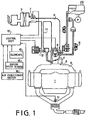
- an internal combustion engine 1 for a motor vehicle is supplied with air through an air cleaner 2, intake pipe 3, throttle valve 4 in a throttle body 5, and an intake manifold 6, mixing with fuel injected from a single point injector 8.
- Fuel in a fuel tank is supplied to the injector 8 by a fuel pump P through a pressure damper 9.
- a solenoid operated auxiliary air valve 12 is provided in a bypass 11 around the throttle valve 4.
- a mass air-flow meter 7 is provided on the intake pipe 3 and an 0 2 -sensor 14 is provided in an exhaust pipe. Output signals of the meter 7 and the sensor 14 are applied to a control unit 10.
- the control unit 10 is also applied with output signals from an engine speed sensor 13, an air conditioner switch 16 and other various elements 15 such as coolant temperature sensor, starter switch and intake air temperature sensor.
- the control unit 10 produces actuating signals to control the injector 8 and the solenoid operated auxiliary valve 12.
- control unit 10 is an electronic fuel injection system and comprises a basic injection pulse width calculator 20 to which a mass air flow signal Q from the mass air-flow meter 7 and an engine speed signal N from the engine speed sensor 13 are applied.
- Basic injection pulse width T p can be obtained by the following equation;
- a comparator 22 to which a feedback signal from the O z -sensor 14 is applied, is provided in the control unit 10.
- the feedback signal is compared with a reference value corresponding to stoichiometric air-fuel ratio to decide whether the air-fuel mixture is appropriate or not.
- the comparator 22 produces an error signal.
- a control coefficient setting section 23 applies a control coefficient signal a to the desired injection pulse width calculator 21 in response to the error signal.
- a correcting coefficient setting section 24 also applies a correcting coefficient K H to the calculator 21 in accordance with the output signals of the correcting elements 15.
- the control unit 10 further comprises a correcting coefficient calculator 26 to which an ON signal of the air-conditioner switch 16 is applied.
- a timer 25 which is also responsive to the ON signal applies a set time signal to the correcting coefficient calculator 26.
- the correcting coefficient calculator 26 sets an initial correcting coefficient K A in order to increase the amount of injection fuel during the set time t represented by the set time signal.
- the coefficient K A gradually decreases with time by the decrement k, and when the set time t lapses, the coefficient K A becomes zero. If the output signal of the air-conditioner switch 16 changes to an OFF signal during the set time t, the coefficient K A instantly becomes zero.
- T i pulse width for correcting the voltage applied to the injector
- An injection signal dependent on the pulse with Ti. is applied to the injector 8 through an output section 27.
- the ON signal of the air-conditioner switch 16 is further applied to the output section 27 which in turn produces an actuating signal to the solenoid operated auxiliary air valve 12 to open it.
- the air-conditioner When the air-conditioner is not used during the operation of the engine 1, the air flows into the intake manifold 6 in accordance with the opening degree of the throttle valve 4. Output signals of the mass air-flow meter 7, sensors 13 and 14, and elements 15 are supplied to the control unit 10 to obtain the desired injection pulse width T i. The injection signal is applied to the injector 8 so as to inject fuel in accordance with the pulse width T i . Accordingly, the air-fuel mixture converges to the stoichiometric ratio in a steady state and is enriched by the coefficient K H in accordance with engine operating conditions.
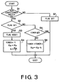
- step S2 when it is determined that the air-conditioner switch 16 is turned on at a step S1, the program proceeds to a step S2.
- the flag is set at step S2, it means that the program is a first loop immediately after the actuation of the air-conditioner, the program proceeds to a step S3, where the flag is reset.
- the timer is set to a set time t and the correcting coefficient K A is obtained, and a decrement k is also calculated.
- the correcting K A is added to the equation for obtaining the desired fuel injection pulse width T i. Accordingly, the amount of fuel is increased so as to compensate the dilution of the mixture caused by increased intake air.
- the air-fuel ratio is maintained approximate to the stoichiometric air-fuel ratio.
- the engine speed starts to increase right after the actuation of the air-conditioner.
- step S5 the program proceeds from step S2 to a step S5, where it is determined whether the remaining time in the timer is equal to or smaller than zero (Timer saup"0) or not. If the value is larger than zero, the program proceeds to a step S6.
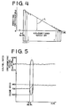
- the correcting coefficient K A is continuously decreased by the decrement k which was calculated at the step S4, and the set time in the timer is also reduced little by little. The operations at steps S5 and S6 are repeated until the set time becomes zero. Accordingly, as shown in Fig. 4, the value of the correcting coefficient K A for increasing the injected fuel decreases with time. Thus the increased amount of fuel to be injected gradually decreases.
- the air flow meter 7 is able to accurately detect the mass air flow so that it is needless to increase the injection fuel by the coefficient K A. Accordingly, when the set time t lapses, the coefficient calculator 26 stops generating the coefficient K A.
- step S7 the flag is set.
- the coefficient K A immediately turns to zero as shown by a dotted line L in Fig. 4, so as to terminate the correcting operation.
- the fuel is temporarily increased to compensate for the dilution occurred at the start of the air-conditioner, so that decrease in engine speed is prevented. Since the actual air-fuel ratio substantially coincides with the stoichiometric ratio, the fuel consumption and emission control are improved.
Claims (3)
Applications Claiming Priority (2)
| Application Number | Priority Date | Filing Date | Title |
|---|---|---|---|
| JP61246155A JPS63100243A (ja) | 1986-10-16 | 1986-10-16 | 燃料噴射装置 |
| JP246155/86 | 1986-10-16 |
Publications (2)
| Publication Number | Publication Date |
|---|---|
| EP0264286A1 EP0264286A1 (fr) | 1988-04-20 |
| EP0264286B1 true EP0264286B1 (fr) | 1990-01-31 |
Family
ID=17144312
Family Applications (1)
| Application Number | Title | Priority Date | Filing Date |
|---|---|---|---|
| EP87309131A Expired EP0264286B1 (fr) | 1986-10-16 | 1987-10-15 | Système de commande de vitesse de moteur d'automobile |
Country Status (4)
| Country | Link |
|---|---|
| US (1) | US4836164A (fr) |
| EP (1) | EP0264286B1 (fr) |
| JP (1) | JPS63100243A (fr) |
| DE (1) | DE3761578D1 (fr) |
Families Citing this family (28)
| Publication number | Priority date | Publication date | Assignee | Title |
|---|---|---|---|---|
| JPH01216054A (ja) * | 1988-02-24 | 1989-08-30 | Fuji Heavy Ind Ltd | エンジンの燃料噴射制御装置 |
| JPH07681Y2 (ja) * | 1988-04-06 | 1995-01-11 | トヨタ自動車株式会社 | アイドル回転速度制御装置 |
| JPH01152819U (fr) * | 1988-04-13 | 1989-10-20 | ||
| US4976589A (en) * | 1988-04-22 | 1990-12-11 | Honda Giken Kogyo K.K. (Honda Motor Co., Ltd.) | Output control system for an I.C. engine responsive to compressor torque and engine speed |
| JPH02108840A (ja) * | 1988-10-19 | 1990-04-20 | Fuji Heavy Ind Ltd | 気化器のアイドリング回転数制御装置 |
| JPH02294537A (ja) * | 1989-05-10 | 1990-12-05 | Mitsubishi Electric Corp | エンジンのアイドル調整方法 |
| JPH03944A (ja) * | 1989-05-29 | 1991-01-07 | Toyota Motor Corp | 内燃機関の空燃比制御装置 |
| US4945878A (en) * | 1989-06-16 | 1990-08-07 | Siemens-Bendix Automotive Electronics L.P. | Extended over temperature operation and controls for ic engine |
| JPH04132859A (ja) * | 1990-09-20 | 1992-05-07 | Mitsubishi Electric Corp | 電子制御式燃料噴射装置 |
| US5186142A (en) * | 1991-07-01 | 1993-02-16 | Briggs & Stratton Corporation | Idling system for a device having a speed governor |
| JPH05280397A (ja) * | 1992-03-31 | 1993-10-26 | Nissan Motor Co Ltd | 内燃機関のアイドル回転制御装置 |
| US5353762A (en) * | 1993-05-10 | 1994-10-11 | Briggs & Stratton Corporation | Modular automatic speed changing system |
| JP3308050B2 (ja) * | 1993-07-19 | 2002-07-29 | 株式会社デンソー | 内燃機関のトルク制御装置 |
| JPH0886232A (ja) * | 1994-07-20 | 1996-04-02 | Nippon Soken Inc | エンジン制御装置 |
| JP3656289B2 (ja) * | 1995-08-07 | 2005-06-08 | 株式会社デンソー | 内燃機関の排気浄化装置 |
| JP3613894B2 (ja) * | 1996-07-22 | 2005-01-26 | 日産自動車株式会社 | 内燃機関のアイドル回転速度制御装置 |
| JP3319304B2 (ja) * | 1996-10-01 | 2002-08-26 | 株式会社デンソー | 車両用暖房装置 |
| KR100398181B1 (ko) * | 2000-11-29 | 2003-09-19 | 현대자동차주식회사 | 차량용 엔진의 에어컨 작동 관련 공 회전수 조절장치 및방법 |
| US8910616B2 (en) | 2011-04-21 | 2014-12-16 | Briggs & Stratton Corporation | Carburetor system for outdoor power equipment |
| US8915231B2 (en) | 2010-03-16 | 2014-12-23 | Briggs & Stratton Corporation | Engine speed control system |
| US8726882B2 (en) | 2010-03-16 | 2014-05-20 | Briggs & Stratton Corporation | Engine speed control system |
| US9316175B2 (en) | 2010-03-16 | 2016-04-19 | Briggs & Stratton Corporation | Variable venturi and zero droop vacuum assist |
| US8560202B2 (en) * | 2010-11-01 | 2013-10-15 | Ford Global Technologies, Llc | Method and apparatus for improved climate control function in a vehicle employing engine stop/start technology |
| US9447765B2 (en) | 2011-07-11 | 2016-09-20 | Ford Global Technologies, Llc | Powertrain delta current estimation method |
| US10480477B2 (en) | 2011-07-11 | 2019-11-19 | Ford Global Technologies, Llc | Electric current based engine auto stop inhibit algorithm and system implementing same |
| US9303613B2 (en) | 2012-02-24 | 2016-04-05 | Ford Global Technologies, Llc | Control of vehicle electrical loads during engine auto stop event |
| JP6156485B2 (ja) * | 2013-03-27 | 2017-07-05 | トヨタ自動車株式会社 | 内燃機関の制御装置 |
| US9248824B2 (en) | 2014-01-24 | 2016-02-02 | Ford Global Technologies, Llc | Rear defrost control in stop/start vehicle |
Family Cites Families (8)
| Publication number | Priority date | Publication date | Assignee | Title |
|---|---|---|---|---|
| JPS5654936A (en) * | 1979-10-10 | 1981-05-15 | Nippon Denso Co Ltd | Control method for air-fuel ratio |
| JPS585438A (ja) * | 1981-07-01 | 1983-01-12 | Mitsubishi Electric Corp | 燃料制御装置 |
| JPS58197449A (ja) * | 1982-04-21 | 1983-11-17 | Honda Motor Co Ltd | 内燃エンジンのエンジン回転数制御方法 |
| JPS58190530A (ja) * | 1982-04-20 | 1983-11-07 | Honda Motor Co Ltd | 内燃エンジンのアイドル回転数フィ−ドバック制御方法 |
| JPS58187535A (ja) * | 1982-04-28 | 1983-11-01 | Mitsubishi Motors Corp | エンジンの出力制御装置 |
| JPS58195041A (ja) * | 1982-05-08 | 1983-11-14 | Honda Motor Co Ltd | 内燃エンジンのアイドル回転数フイ−ドバツク制御方法 |
| US4625281A (en) * | 1984-08-15 | 1986-11-25 | Motorola, Inc. | Engine load transient compensation system |
| JP3010919B2 (ja) * | 1992-08-18 | 2000-02-21 | 日本電気株式会社 | 電界効果型化合物半導体装置 |
-
1986
- 1986-10-16 JP JP61246155A patent/JPS63100243A/ja active Pending
-
1987
- 1987-10-09 US US07/107,653 patent/US4836164A/en not_active Expired - Fee Related
- 1987-10-15 DE DE8787309131T patent/DE3761578D1/de not_active Expired - Fee Related
- 1987-10-15 EP EP87309131A patent/EP0264286B1/fr not_active Expired
Also Published As
| Publication number | Publication date |
|---|---|
| US4836164A (en) | 1989-06-06 |
| JPS63100243A (ja) | 1988-05-02 |
| DE3761578D1 (de) | 1990-03-08 |
| EP0264286A1 (fr) | 1988-04-20 |
Similar Documents
| Publication | Publication Date | Title |
|---|---|---|
| EP0264286B1 (fr) | Système de commande de vitesse de moteur d'automobile | |
| US4442815A (en) | Optimum air-fuel ratio control for internal combustion engine | |
| US4841940A (en) | Air-fuel ratio control device of an internal combustion engine | |
| KR920005851B1 (ko) | 연료 제어 장치 | |
| JPH09250413A (ja) | 流量制御弁の周期的操作方法 | |
| EP0216071B1 (fr) | Méthode et appareil de réglage électronique du ralenti de moteurs à combustion interne | |
| US4796591A (en) | Internal combustion engine control system | |
| US4480621A (en) | Control apparatus for a fuel metering system in an internal combustion engine | |
| US5722368A (en) | Method and apparatus for adjusting the intake air flow rate of an internal combustion engine | |
| US4549512A (en) | Intake air amount control apparatus of internal combustion engine | |
| US4612889A (en) | Idle control method for an internal combustion engine | |
| JPH03488B2 (fr) | ||
| EP0257844A1 (fr) | Commande de rapport air/carburant pour moteur | |
| JP2518619B2 (ja) | 内燃機関の吸入空気量制御装置 | |
| JPS6299652A (ja) | 内燃機関の燃焼制御装置 | |
| JPH02104942A (ja) | 内燃機関の混合燃料供給装置 | |
| JPH0747943B2 (ja) | 内燃機関の電子制御燃料噴射装置 | |
| JPH0577867B2 (fr) | ||
| JPH0452854B2 (fr) | ||
| JP2633618B2 (ja) | エンジンの蒸発燃料供給装置 | |
| JPH0684732B2 (ja) | エンジンのアイドル回転数制御装置 | |
| JP3014541B2 (ja) | 内燃機関の空燃比制御方法 | |
| JPS6123845A (ja) | 空燃比制御装置 | |
| JPH0517398Y2 (fr) | ||
| JP2807557B2 (ja) | エンジン始動後の燃料制御方法 |
Legal Events
| Date | Code | Title | Description |
|---|---|---|---|
| PUAI | Public reference made under article 153(3) epc to a published international application that has entered the european phase |
Free format text: ORIGINAL CODE: 0009012 |
|
| 17P | Request for examination filed |
Effective date: 19871030 |
|
| AK | Designated contracting states |
Kind code of ref document: A1 Designated state(s): DE GB |
|
| 17Q | First examination report despatched |
Effective date: 19890118 |
|
| GRAA | (expected) grant |
Free format text: ORIGINAL CODE: 0009210 |
|
| AK | Designated contracting states |
Kind code of ref document: B1 Designated state(s): DE GB |
|
| REF | Corresponds to: |
Ref document number: 3761578 Country of ref document: DE Date of ref document: 19900308 |
|
| PLBE | No opposition filed within time limit |
Free format text: ORIGINAL CODE: 0009261 |
|
| STAA | Information on the status of an ep patent application or granted ep patent |
Free format text: STATUS: NO OPPOSITION FILED WITHIN TIME LIMIT |
|
| 26N | No opposition filed | ||
| PGFP | Annual fee paid to national office [announced via postgrant information from national office to epo] |
Ref country code: GB Payment date: 19911010 Year of fee payment: 5 |
|
| PGFP | Annual fee paid to national office [announced via postgrant information from national office to epo] |
Ref country code: DE Payment date: 19911028 Year of fee payment: 5 |
|
| PG25 | Lapsed in a contracting state [announced via postgrant information from national office to epo] |
Ref country code: GB Effective date: 19921015 |
|
| GBPC | Gb: european patent ceased through non-payment of renewal fee |
Effective date: 19921015 |
|
| PG25 | Lapsed in a contracting state [announced via postgrant information from national office to epo] |
Ref country code: DE Effective date: 19930701 |