EP0258880A2 - Cantre d'ourdissage - Google Patents
Cantre d'ourdissage Download PDFInfo
- Publication number
- EP0258880A2 EP0258880A2 EP87112781A EP87112781A EP0258880A2 EP 0258880 A2 EP0258880 A2 EP 0258880A2 EP 87112781 A EP87112781 A EP 87112781A EP 87112781 A EP87112781 A EP 87112781A EP 0258880 A2 EP0258880 A2 EP 0258880A2
- Authority
- EP
- European Patent Office
- Prior art keywords
- gate
- warping
- thread
- threads
- creel
- Prior art date
- Legal status (The legal status is an assumption and is not a legal conclusion. Google has not performed a legal analysis and makes no representation as to the accuracy of the status listed.)
- Ceased
Links
Images


Classifications
-
- D—TEXTILES; PAPER
- D02—YARNS; MECHANICAL FINISHING OF YARNS OR ROPES; WARPING OR BEAMING
- D02H—WARPING, BEAMING OR LEASING
- D02H1/00—Creels, i.e. apparatus for supplying a multiplicity of individual threads
Definitions
- the present invention relates to warping gates in which the bobbins of the threads to be warped are arranged next to and on top of one another. It enables constant access to each spool even during warping.
- the invention provides thread guides that can be pivoted out and behind which the thread packages to be sharpened are located and can be accessed by pivoting out the gate doors.
- the creel according to the invention has thread guiding elements which initially guide each thread vertically or approximately vertically over the creel, deflect it there into the horizontal and guide it to the warping machine. Through these measures, each coil is accessible even during warping and can, for. B. can be easily replaced in the event of yarn defects.
- each thread drawn approximately horizontally from the bobbin can be guided through the thread guide through approximately 90 ° into the vertical.
- the thread, which now rises vertically, is deflected by a deflection of approximately 90 ° in a horizontal direction leading to the central aisle.
- Each thread thus undergoes a change in direction by approximately 90 ° three times.
- rakes or eyelets can be used.
- the use of guide tubes as thread guide elements is preferred. They protect the thread against dirt and damage, for example when the warping system is at a standstill.
- an eye brake can be provided for each thread according to a further embodiment of the invention. By moving this eyelet brake perpendicular to the thread running direction, different frictional resistances can be built up, which compensate for differences in the length-related friction in the pipes.
- These Eyelet brakes can also be jointly adjustable for a group of threads that pass through guide tubes of approximately the same length.
- the gate should also have a clamping brake, in particular a plate brake for each thread.
- a clamping brake in particular a plate brake for each thread.
- the tension in the thread can be maintained when the warping machine is stopped or running slowly, while the brake is released when the warping machine is running fast, thus avoiding an additional pull on the thread.
- disc brakes In order to quickly have the braking effect of the disc brake available when starting and stopping the warping machine, disc brakes have proven to be particularly suitable which open or close the brake by gas pressure against spring force.
- the measures mentioned enable the gate to be set up in a space-saving manner even when a large number of threads are to be warmed.
- the coils arranged side by side and one above the other are set up in rows which are separated from one another by walkways.
- Gate posts and doors can be arranged on both sides of the aisles so that 2 rows of coils can be operated from one aisle.
- An advantageous arrangement of the gate results from the fact that the rows of the coils arranged one above the other and next to one another, or of the gate posts and doors, are arranged perpendicular to the central aisle leading to the warping machine on both sides.
- the width of the center aisle should be such that it corresponds at least to the diagonal length of a warping carriage.
- the rows of gates on both sides can be fed from the central aisle.
- the arrangement of the gate according to the invention makes it possible, for example, to simultaneously sharpen l280 threads with a bobbin diameter of 450 mm on a base area of approximately l80 m2.
- a footprint of less than 400 m2 is sufficient even for 2.5 times the number of threads.
- Fig. L shows the installation of a gate Parking spaces 2 and 2 ⁇ for 40 rail cars in 10 rows of 2 cars on either side of the central aisle l. If gate wagons with l6 spools each are used on both sides, l280 threads can be sharpened.
- Another possibility is the placement of 3 gate carriages in a row, whereby 306 threads can be sharpened at the same time with 16 rows on each side of the central aisle 1 and gate carriages of the type described. The same number can also be achieved with 12 rows on each side of the central aisle and 4 gate cars in a row. It is also possible to operate several warping machines from this gate at the same time.
- catwalks 3 and 3 ⁇ Between the parking spaces 2 and 2 ⁇ for gate wagons there are catwalks 3 and 3 ⁇ , from which the gate wagons inserted through the central aisle l and the guiding devices such as eyelet and parking brakes are accessible.
- the above-mentioned creel has a total of 80 groups of 16 strands, one on top of the other, when using the above-mentioned creel carriages, each equipped with 16 coils.
- the warping machine is designated by 6 and the associated monitoring and auxiliary apparatuses such as fluff detector, thread store, oil device are designated by 5.
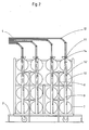
- FIG. 2 shows part of the gate with the retracted gate carriage 7, seen in the warping direction.
- the gate consists of the gate posts 8, on which the gate doors 9 are pivotally attached.
- the pivoting of the gate doors 9 enables access to the individual bobbins 10 and, for example, the replacement of a bobbin if there is a damaged thread on it.
- the threads 4 are initially guided approximately vertically upward from the gate doors 9 and, after being deflected twice, run horizontally to the central aisle in each case by 45 °.
- FIG. 3 shows the upper part of a gate door 9.
- the threads 4 are deflected by 90 ° through the thread guide eyelets l4 ⁇ and reach the thread guides l4 also fastened to the gate door 9 in a vertical upward direction.
- the size of the braking force exerted by the eyelet brakes 11 is determined by moving the carriage perpendicular to the direction of travel of the threads and thus by the size of the angles by which the threads are deflected from straight running.
- the guide tubes l2 serve as thread guide members for further guiding the threads upwards.
- the gate is shown with a retracted gate carriage 7, perpendicular to the central aisle in the viewing direction.
- the gate carriage 7 is equipped with coils 10 on both sides, but the gate members are only shown on one side of the carriage 7 or the catwalk 3.
- the threads 4 are guided via the thread guides l4 ⁇ , clamping brakes l3, thread guides l4 ⁇ and l4 and eyelet brakes ll attached to the gate door 9 upwards and there, as described for FIG. 2, in a horizontal direction to the central aisle and to the warping machine.
Landscapes
- Engineering & Computer Science (AREA)
- Textile Engineering (AREA)
- Warping, Beaming, Or Leasing (AREA)
- Securing Of Glass Panes Or The Like (AREA)
Applications Claiming Priority (2)
| Application Number | Priority Date | Filing Date | Title |
|---|---|---|---|
| DE19863629927 DE3629927A1 (de) | 1986-09-03 | 1986-09-03 | Schaergatter |
| DE3629927 | 1986-09-03 |
Publications (2)
| Publication Number | Publication Date |
|---|---|
| EP0258880A2 true EP0258880A2 (fr) | 1988-03-09 |
| EP0258880A3 EP0258880A3 (fr) | 1990-08-29 |
Family
ID=6308791
Family Applications (1)
| Application Number | Title | Priority Date | Filing Date |
|---|---|---|---|
| EP87112781A Ceased EP0258880A3 (fr) | 1986-09-03 | 1987-09-02 | Cantre d'ourdissage |
Country Status (3)
| Country | Link |
|---|---|
| US (1) | US4852824A (fr) |
| EP (1) | EP0258880A3 (fr) |
| DE (1) | DE3629927A1 (fr) |
Cited By (3)
| Publication number | Priority date | Publication date | Assignee | Title |
|---|---|---|---|---|
| FR2629840A1 (fr) * | 1988-04-06 | 1989-10-13 | Bordmann Jean Claude | Cantre d'ourdissage et procede de garnissage d'un tel cantre |
| WO1992013123A1 (fr) * | 1991-01-16 | 1992-08-06 | Colin Philip Smith | Systeme d'alimentation en fil |
| CN106592046A (zh) * | 2016-12-14 | 2017-04-26 | 马鞍山金姿纺织装饰用品有限公司 | 一种分条整经方法 |
Families Citing this family (7)
| Publication number | Priority date | Publication date | Assignee | Title |
|---|---|---|---|---|
| DE4021590A1 (de) * | 1990-07-06 | 1992-01-09 | Leonhard Hauers | Spannungs-ausgleichsvorrichtung fuer spulenablaufgatter |
| DE202005015262U1 (de) * | 2005-09-27 | 2006-11-16 | Autefa Automation Gmbh | Gatterablauf |
| US7802749B2 (en) * | 2007-01-19 | 2010-09-28 | Automated Creel Systems, Inc. | Creel magazine supply system and method |
| US7806360B2 (en) * | 2007-10-19 | 2010-10-05 | Automated Creel Systems, Inc. | Creel magazine supply system and method |
| US8172170B2 (en) * | 2008-10-15 | 2012-05-08 | Columbia Insurance Company | Modular creel |
| US20110127364A1 (en) * | 2009-12-01 | 2011-06-02 | Rees John J M | Mobile creel |
| USD801400S1 (en) * | 2015-03-20 | 2017-10-31 | Tek Group International | Creel roller guide |
Citations (5)
| Publication number | Priority date | Publication date | Assignee | Title |
|---|---|---|---|---|
| DE741382C (de) * | 1939-05-10 | 1943-11-10 | Schlafhorst & Co W | Spulengatter |
| GB589924A (en) * | 1945-02-16 | 1947-07-03 | British Bemberg Ltd | Improvements in or relating to creels for warping machines |
| FR992892A (fr) * | 1944-09-22 | 1951-10-24 | Perfectionnements apportés aux cantres, notamment à celles pour l'ourdissage des fils destinés au tissage | |
| GB1125854A (en) * | 1966-01-18 | 1968-09-05 | Jefferson Mills Company Inc | Improvements in and relating to creels for supplying warp yarns |
| DE3103555A1 (de) * | 1981-02-03 | 1982-10-14 | W. Schlafhorst & Co, 4050 Mönchengladbach | Kettvorbereitungsmaschine |
Family Cites Families (21)
| Publication number | Priority date | Publication date | Assignee | Title |
|---|---|---|---|---|
| US1824356A (en) * | 1928-07-14 | 1931-09-22 | Universal Winding Co | Creel |
| US2050775A (en) * | 1934-04-09 | 1936-08-11 | Eugene R Alderman | Warping apparatus |
| US2177855A (en) * | 1936-01-06 | 1939-10-31 | Celanese Corp | Warp creel |
| DE685482C (de) * | 1936-03-17 | 1939-12-20 | Schlafhorst & Co W | Spulengatter fuer Zettel- und Schermaschinen |
| US2259079A (en) * | 1938-01-14 | 1941-10-14 | Schlafhorst & Co W | Creel mechanism of warping frames |
| US2325974A (en) * | 1943-05-10 | 1943-08-03 | Peter C Pasquerello | Creel apparatus |
| GB670535A (en) * | 1949-08-09 | 1952-04-23 | Tatlock Engineering Co Ltd | Improvements in creels for warping, beaming and like textile machines |
| DE1039450B (de) * | 1953-06-15 | 1958-09-18 | Wilhelm Klein | Zentralsteuerbare Fadenbremsvorrichtung fuer die gleichzeitige Einzel-Spannung von Faeden, insbesondere fuer Zettel- und Schaergatter |
| DE2048529A1 (de) * | 1970-10-02 | 1972-04-06 | W. Schlafhorst & Co, 4050 Mönchengladbach | Spulengatter für Textilmaschinen |
| GB1370915A (en) * | 1972-09-04 | 1974-10-16 | Shorell Ltd | Yarn creel |
| DE2344906B1 (de) * | 1973-09-06 | 1974-11-21 | Mayer Textilmaschf | Schaergatter |
| DE2360507A1 (de) * | 1973-12-05 | 1975-06-19 | Nino Ag | Spulengatter |
| US3875883A (en) * | 1974-03-06 | 1975-04-08 | Aldon Ind Inc | Method and apparatus for tufting multicolored products |
| DE3128933A1 (de) * | 1981-07-22 | 1983-03-24 | W. Schlafhorst & Co, 4050 Mönchengladbach | Gatter |
| DE3146170A1 (de) * | 1981-11-21 | 1983-05-26 | W. Schlafhorst & Co, 4050 Mönchengladbach | Gatter |
| DE3211924A1 (de) * | 1982-03-31 | 1983-10-13 | W. Schlafhorst & Co, 4050 Mönchengladbach | Fadenspannvorrichtung |
| DE3429153C2 (de) * | 1983-08-10 | 1986-11-27 | Barmag Barmer Maschinenfabrik Ag, 5630 Remscheid | Spulengatter |
| US4552321A (en) * | 1984-02-06 | 1985-11-12 | Raeckelboom Marc A | Strand guide |
| US4538776A (en) * | 1984-03-14 | 1985-09-03 | West Point Foundry & Machine Co. | Creel apparatus |
| DE8428057U1 (de) * | 1984-09-24 | 1985-05-30 | Barth, Peter, 7455 Jungingen | Spulengatter mit integrierten garnleitroehren |
| US4572458A (en) * | 1984-11-14 | 1986-02-25 | American Barmag Corporation | Compact creel for large diameter yarn supply packages |
-
1986
- 1986-09-03 DE DE19863629927 patent/DE3629927A1/de not_active Ceased
-
1987
- 1987-09-02 EP EP87112781A patent/EP0258880A3/fr not_active Ceased
- 1987-09-03 US US07/095,436 patent/US4852824A/en not_active Expired - Fee Related
Patent Citations (5)
| Publication number | Priority date | Publication date | Assignee | Title |
|---|---|---|---|---|
| DE741382C (de) * | 1939-05-10 | 1943-11-10 | Schlafhorst & Co W | Spulengatter |
| FR992892A (fr) * | 1944-09-22 | 1951-10-24 | Perfectionnements apportés aux cantres, notamment à celles pour l'ourdissage des fils destinés au tissage | |
| GB589924A (en) * | 1945-02-16 | 1947-07-03 | British Bemberg Ltd | Improvements in or relating to creels for warping machines |
| GB1125854A (en) * | 1966-01-18 | 1968-09-05 | Jefferson Mills Company Inc | Improvements in and relating to creels for supplying warp yarns |
| DE3103555A1 (de) * | 1981-02-03 | 1982-10-14 | W. Schlafhorst & Co, 4050 Mönchengladbach | Kettvorbereitungsmaschine |
Cited By (3)
| Publication number | Priority date | Publication date | Assignee | Title |
|---|---|---|---|---|
| FR2629840A1 (fr) * | 1988-04-06 | 1989-10-13 | Bordmann Jean Claude | Cantre d'ourdissage et procede de garnissage d'un tel cantre |
| WO1992013123A1 (fr) * | 1991-01-16 | 1992-08-06 | Colin Philip Smith | Systeme d'alimentation en fil |
| CN106592046A (zh) * | 2016-12-14 | 2017-04-26 | 马鞍山金姿纺织装饰用品有限公司 | 一种分条整经方法 |
Also Published As
| Publication number | Publication date |
|---|---|
| US4852824A (en) | 1989-08-01 |
| EP0258880A3 (fr) | 1990-08-29 |
| DE3629927A1 (de) | 1988-03-10 |
Similar Documents
| Publication | Publication Date | Title |
|---|---|---|
| EP0258880A2 (fr) | Cantre d'ourdissage | |
| DE2841210A1 (de) | Einrichtung zur ballonbegrenzung an einem spulengatter | |
| DE102007018536A1 (de) | Offenend-Spinnmaschine | |
| DE1907782B2 (de) | Spinnstreckspulmaschine | |
| EP1245705A2 (fr) | Procédé et dispositif d'optimisation de la vitesse de déroulage sur un cantre | |
| DE3931878C2 (de) | Texturiermaschine | |
| DE2246231C3 (de) | Spulengatter | |
| DE69911214T2 (de) | Verschlingungsschutz für einen fadenlieferspeicher | |
| DE102017010143A1 (de) | Vorrichtung zum Abziehen und Aufwickeln mehrerer Fäden | |
| DE2454900A1 (de) | Offenend-spinnmaschine mit wenigstens einer verfahrbaren wartungseinrichtung | |
| DE4115059C2 (de) | Vorrichtung zum Begrenzen der Fadenballons an einem Spulengatter | |
| EP0904436B1 (fr) | Dispositif d'enroulement pour fils de cantres | |
| DE1955042U (de) | Spinnaggregat mit aufspuleinrichtung. | |
| DE3817678C1 (en) | Cabling machine for double twisting - has supporting cross wall on machine frame after every second spindle | |
| DE102018125622A1 (de) | Verfahren zum Betreiben einer Spulvorrichtung | |
| DE3841055C2 (fr) | ||
| DE939527C (de) | Kloeppel fuer Drahtflechtmaschinen | |
| DE733668C (de) | Fadenbremse fuer Zettelgatter mit vorgeschaltetem Fadenspannergitter | |
| DE2325841C3 (de) | Spulensortier- und Speichereinrichtung für mit Wickelgut bewickelte Spulen zur sortierten Bereitstellung und Vorratshaltung | |
| DE7629298U1 (de) | Spulen-gatter fuer textilmaschinen | |
| DE102022002956A1 (de) | Vorrichtung zum Verwirbeln von einer Mehrzahl von Filamenten eines synthetischen Fadens | |
| DE102010056269A1 (de) | Vorrichtung zum Aufwickeln synthetischer Fäden | |
| EP0534896B1 (fr) | Dispositif et procédé pour limiter le ballon sur un cantre | |
| DE1710617C3 (de) | Maschine zur Herstellung gekräuselter Textilgarne aus synthetischen Materialien | |
| DE2344906B1 (de) | Schaergatter |
Legal Events
| Date | Code | Title | Description |
|---|---|---|---|
| PUAI | Public reference made under article 153(3) epc to a published international application that has entered the european phase |
Free format text: ORIGINAL CODE: 0009012 |
|
| AK | Designated contracting states |
Kind code of ref document: A2 Designated state(s): AT BE CH DE ES FR GB GR IT LI LU NL SE |
|
| PUAL | Search report despatched |
Free format text: ORIGINAL CODE: 0009013 |
|
| AK | Designated contracting states |
Kind code of ref document: A3 Designated state(s): AT BE CH DE ES FR GB GR IT LI LU NL SE |
|
| 17P | Request for examination filed |
Effective date: 19910201 |
|
| 17Q | First examination report despatched |
Effective date: 19920616 |
|
| STAA | Information on the status of an ep patent application or granted ep patent |
Free format text: STATUS: THE APPLICATION HAS BEEN REFUSED |
|
| 18R | Application refused |
Effective date: 19931219 |
|
| RIN1 | Information on inventor provided before grant (corrected) |
Inventor name: BEITZ, JUERGEN Inventor name: ERREN, KARL-HEINZ Inventor name: MANTZ, EKKEHARD |