EP0258880A2 - Warping creel - Google Patents
Warping creel Download PDFInfo
- Publication number
- EP0258880A2 EP0258880A2 EP87112781A EP87112781A EP0258880A2 EP 0258880 A2 EP0258880 A2 EP 0258880A2 EP 87112781 A EP87112781 A EP 87112781A EP 87112781 A EP87112781 A EP 87112781A EP 0258880 A2 EP0258880 A2 EP 0258880A2
- Authority
- EP
- European Patent Office
- Prior art keywords
- gate
- warping
- thread
- threads
- creel
- Prior art date
- Legal status (The legal status is an assumption and is not a legal conclusion. Google has not performed a legal analysis and makes no representation as to the accuracy of the status listed.)
- Ceased
Links
Images


Classifications
-
- D—TEXTILES; PAPER
- D02—YARNS; MECHANICAL FINISHING OF YARNS OR ROPES; WARPING OR BEAMING
- D02H—WARPING, BEAMING OR LEASING
- D02H1/00—Creels, i.e. apparatus for supplying a multiplicity of individual threads
Definitions
- the present invention relates to warping gates in which the bobbins of the threads to be warped are arranged next to and on top of one another. It enables constant access to each spool even during warping.
- the invention provides thread guides that can be pivoted out and behind which the thread packages to be sharpened are located and can be accessed by pivoting out the gate doors.
- the creel according to the invention has thread guiding elements which initially guide each thread vertically or approximately vertically over the creel, deflect it there into the horizontal and guide it to the warping machine. Through these measures, each coil is accessible even during warping and can, for. B. can be easily replaced in the event of yarn defects.
- each thread drawn approximately horizontally from the bobbin can be guided through the thread guide through approximately 90 ° into the vertical.
- the thread, which now rises vertically, is deflected by a deflection of approximately 90 ° in a horizontal direction leading to the central aisle.
- Each thread thus undergoes a change in direction by approximately 90 ° three times.
- rakes or eyelets can be used.
- the use of guide tubes as thread guide elements is preferred. They protect the thread against dirt and damage, for example when the warping system is at a standstill.
- an eye brake can be provided for each thread according to a further embodiment of the invention. By moving this eyelet brake perpendicular to the thread running direction, different frictional resistances can be built up, which compensate for differences in the length-related friction in the pipes.
- These Eyelet brakes can also be jointly adjustable for a group of threads that pass through guide tubes of approximately the same length.
- the gate should also have a clamping brake, in particular a plate brake for each thread.
- a clamping brake in particular a plate brake for each thread.
- the tension in the thread can be maintained when the warping machine is stopped or running slowly, while the brake is released when the warping machine is running fast, thus avoiding an additional pull on the thread.
- disc brakes In order to quickly have the braking effect of the disc brake available when starting and stopping the warping machine, disc brakes have proven to be particularly suitable which open or close the brake by gas pressure against spring force.
- the measures mentioned enable the gate to be set up in a space-saving manner even when a large number of threads are to be warmed.
- the coils arranged side by side and one above the other are set up in rows which are separated from one another by walkways.
- Gate posts and doors can be arranged on both sides of the aisles so that 2 rows of coils can be operated from one aisle.
- An advantageous arrangement of the gate results from the fact that the rows of the coils arranged one above the other and next to one another, or of the gate posts and doors, are arranged perpendicular to the central aisle leading to the warping machine on both sides.
- the width of the center aisle should be such that it corresponds at least to the diagonal length of a warping carriage.
- the rows of gates on both sides can be fed from the central aisle.
- the arrangement of the gate according to the invention makes it possible, for example, to simultaneously sharpen l280 threads with a bobbin diameter of 450 mm on a base area of approximately l80 m2.
- a footprint of less than 400 m2 is sufficient even for 2.5 times the number of threads.
- Fig. L shows the installation of a gate Parking spaces 2 and 2 ⁇ for 40 rail cars in 10 rows of 2 cars on either side of the central aisle l. If gate wagons with l6 spools each are used on both sides, l280 threads can be sharpened.
- Another possibility is the placement of 3 gate carriages in a row, whereby 306 threads can be sharpened at the same time with 16 rows on each side of the central aisle 1 and gate carriages of the type described. The same number can also be achieved with 12 rows on each side of the central aisle and 4 gate cars in a row. It is also possible to operate several warping machines from this gate at the same time.
- catwalks 3 and 3 ⁇ Between the parking spaces 2 and 2 ⁇ for gate wagons there are catwalks 3 and 3 ⁇ , from which the gate wagons inserted through the central aisle l and the guiding devices such as eyelet and parking brakes are accessible.
- the above-mentioned creel has a total of 80 groups of 16 strands, one on top of the other, when using the above-mentioned creel carriages, each equipped with 16 coils.
- the warping machine is designated by 6 and the associated monitoring and auxiliary apparatuses such as fluff detector, thread store, oil device are designated by 5.
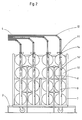
- FIG. 2 shows part of the gate with the retracted gate carriage 7, seen in the warping direction.
- the gate consists of the gate posts 8, on which the gate doors 9 are pivotally attached.
- the pivoting of the gate doors 9 enables access to the individual bobbins 10 and, for example, the replacement of a bobbin if there is a damaged thread on it.
- the threads 4 are initially guided approximately vertically upward from the gate doors 9 and, after being deflected twice, run horizontally to the central aisle in each case by 45 °.
- FIG. 3 shows the upper part of a gate door 9.
- the threads 4 are deflected by 90 ° through the thread guide eyelets l4 ⁇ and reach the thread guides l4 also fastened to the gate door 9 in a vertical upward direction.
- the size of the braking force exerted by the eyelet brakes 11 is determined by moving the carriage perpendicular to the direction of travel of the threads and thus by the size of the angles by which the threads are deflected from straight running.
- the guide tubes l2 serve as thread guide members for further guiding the threads upwards.
- the gate is shown with a retracted gate carriage 7, perpendicular to the central aisle in the viewing direction.
- the gate carriage 7 is equipped with coils 10 on both sides, but the gate members are only shown on one side of the carriage 7 or the catwalk 3.
- the threads 4 are guided via the thread guides l4 ⁇ , clamping brakes l3, thread guides l4 ⁇ and l4 and eyelet brakes ll attached to the gate door 9 upwards and there, as described for FIG. 2, in a horizontal direction to the central aisle and to the warping machine.
Abstract
l. Schärgatter, 2.l Schärgatter, bei denen die Spulen der zu schärenden Fäden neben- und übereinander angeordnet sind, sollen eine ständige Zugänglichkeit jeder Spule auch während des Schärens ermöglichen. Insbesondere soll eine platzsparende Aufstellung des Gatters auch dann ermöglicht werden, wenn eine größere Zahl von Fäden geschärt werden soll. 2.l Es werden Fadenführer (l4, l4', l4") tragende Gattertüren (9) vorgesehen. Hinter den Gattertüren (9) befinden sich die zu schärenden Fadenwickel. Hierdurch wird Zugang zu den einzelnen Spulen (l0) oder Gruppen von Spulen gegeben. Jeder Faden (4) wird zunächst vertikal über das Gatter und anschließend horizontal oberhalb des Gatters zur Schärmaschine (6) über Leitorgane (l2) geführt. 2.3 Bei einer vorteilhaften Aufstellung des Gatters werden die Reihen der über- und nebeneinander angeordneten Spulen bzw. der Gatterpfosten und -türen beiderseits eines zur Schärmaschine führenden Mittelganges senkrecht zu diesem angeordnet. So können auf einer Grundfläche von ca. l80 m² gleichzeitig l280 Fäden bei einem Spulendurchmesser von 450 mm geschärt werden (Fig. 2).l. Warping creel, 2.l warping creel, in which the bobbins of the threads to be warped are arranged next to and on top of each other, should allow constant accessibility of each bobbin even during warping. In particular, a space-saving arrangement of the gate should also be made possible when a larger number of threads is to be warmed. 2.l There are thread guides (l4, l4 ', l4 ") carrying gate doors (9). Behind the gate doors (9) are the thread windings to be sharpened. This gives access to the individual bobbins (l0) or groups of bobbins Each thread (4) is first fed vertically over the creel and then horizontally above the gate to the warping machine (6) via guide elements (l2) 2.3 In an advantageous arrangement of the gate, the rows of the bobbins arranged one above the other and next to one another Gate posts and doors are arranged on both sides of a central aisle leading to the warping machine, so that at a base area of approximately 180 m 2, 280 threads can be warmed at a bobbin diameter of 450 mm (Fig. 2).
Description
Die vorliegende Erfindung betrifft Schärgatter, bei denen die Spulen der zu schärenden Fäden neben- und übereinander angeordnet sind. Sie ermöglicht eine ständige Zugänglichkeit jeder Spule auch während des Schärens.The present invention relates to warping gates in which the bobbins of the threads to be warped are arranged next to and on top of one another. It enables constant access to each spool even during warping.
Hierfür sieht die Erfindung Fadenführer tragende, ausschwenkbare Gattertüren vor, hinter denen sich die zu schärenden Fadenwickel befinden und durch das Ausschwenken der Gattertüren zugänglich werden. Weiterhin weist das erfindungsgemäße Gatter Fadenleitorgane auf, die jeden Faden zunächst senkrecht oder etwa senkrecht über das Gatter führen, dort in die Horizontale umlenken und zur Schärmaschine leiten. Durch diese Maßnahmen ist jede Spule auch während des Schärens zugänglich und kann, z. B. bei Garnfehlern einfach ausgewechselt werden.For this purpose, the invention provides thread guides that can be pivoted out and behind which the thread packages to be sharpened are located and can be accessed by pivoting out the gate doors. Furthermore, the creel according to the invention has thread guiding elements which initially guide each thread vertically or approximately vertically over the creel, deflect it there into the horizontal and guide it to the warping machine. Through these measures, each coil is accessible even during warping and can, for. B. can be easily replaced in the event of yarn defects.
Um zu gewährleisten, daß die Reibungswiderstände für alle Fäden etwa gleich sind, werden nach einer weiteren Ausbildung der Erfindung die Führungen und Leitorgane aller Fäden mit gleichen Umlenkungen ausgestattet. Zum Beispiel kann jeder etwa horizontal von der Spule abgezogene Faden durch Fadenführer um etwa 90° in die Vertikale geleitet werden. Der nun senkrecht aufsteigende Faden wird durch eine Umlenkung um etwa 90° in eine horizontale, zum Mittelgang führende Richtung umgelenkt. Am Mittelgang erfolgt dann eine weitere Umlenkung um etwa 90° in Richtung zur Schärmaschine. Jeder Faden erfährt somit dreimal eine Richtungsänderung um ca. 90°.In order to ensure that the frictional resistances for all threads are approximately the same, the guides and guide elements of all threads are equipped with the same deflections according to a further embodiment of the invention. For example, each thread drawn approximately horizontally from the bobbin can be guided through the thread guide through approximately 90 ° into the vertical. The thread, which now rises vertically, is deflected by a deflection of approximately 90 ° in a horizontal direction leading to the central aisle. Then there is another in the central aisle Redirection by about 90 ° towards the warping machine. Each thread thus undergoes a change in direction by approximately 90 ° three times.
Zur Führung der Fäden über das Gatter und oberhalb des Gatters können Leitorgane üblicher Art, z. B. Rechen oder Ösen eingesetzt werden. Bevorzugt wird die Verwendung von Führungsrohren als Fadenleitorgane. Sie schützen den Faden gegen Verschmutzung und gegen Beschädigung, zum Beispiel während des Stillstandes der Schäranlage.To guide the threads over the gate and above the gate guide elements of the usual type, for. B. rakes or eyelets can be used. The use of guide tubes as thread guide elements is preferred. They protect the thread against dirt and damage, for example when the warping system is at a standstill.
Als zweckmäßig hat es sich erwiesen, die einzelnen geraden Teile der Führungsrohre durch Rohre aus Kunststoff, die ggf. entsprechend dem Umlenkwinkel gebogen sind und auf die geraden Rohrteile aufgeschoben werden, luftdicht zu verbinden. Diese Kunststoffsteckverbindungen ermöglichen durch den luftdichten Abschluß ein Ansaugen der Fäden mittels üblicher Injektoren.It has proven to be expedient to connect the individual straight parts of the guide tubes in an airtight manner by means of plastic tubes which may be bent according to the deflection angle and which are pushed onto the straight tube parts. These plastic plug connections enable the threads to be sucked in by means of conventional injectors due to the airtight seal.
Zum Ausgleich der Unterschiede in den Reibungswiderständen, die sich durch verschiedene Längen der Führungsrohre zwischen Gatter und Schärmaschine ergeben, kann nach einer weiteren Ausbildung der Erfindung für jeden Faden eine Ösenbremse vorgesehen werden. Durch Verschieben dieser Ösenbremse senkrecht zur Fadenlaufrichtung lassen sich unterschiedliche Reibungswiderstände aufbauen, die Unterschiede der längenbedingten Reibung in den Rohrleitungen ausgleichen. Diese Ösenbremsen können auch jeweils für eine Gruppe von Fäden, die etwa gleich lange Führungsrohre durchlaufen, gemeinsam verstellbar sein.To compensate for the differences in the frictional resistances that result from different lengths of the guide tubes between the creel and warping machine, an eye brake can be provided for each thread according to a further embodiment of the invention. By moving this eyelet brake perpendicular to the thread running direction, different frictional resistances can be built up, which compensate for differences in the length-related friction in the pipes. These Eyelet brakes can also be jointly adjustable for a group of threads that pass through guide tubes of approximately the same length.
Auch sollte das Gatter eine Klemmbremse, insbesondere eine Tellerbremse für jeden Faden besitzen. Mit diesen Bremsen kann beim Halt oder langsamen Lauf der Schärmaschine die Spannung im Faden erhalten werden, während die Bremse beim schnellen Lauf der Schärmaschine geöffnet ist und so einen zusätzlichen Zug auf den Faden vermeidet. Um beim An- und Abfahren der Schärmaschine schnell die Bremswirkung der Tellerbremse zur Verfügung zu haben, haben sich Tellerbremsen als besonders geeignet erwiesen, die durch Gasdruck gegen Federkraft die Bremse öffnen oder schließen.The gate should also have a clamping brake, in particular a plate brake for each thread. With these brakes, the tension in the thread can be maintained when the warping machine is stopped or running slowly, while the brake is released when the warping machine is running fast, thus avoiding an additional pull on the thread. In order to quickly have the braking effect of the disc brake available when starting and stopping the warping machine, disc brakes have proven to be particularly suitable which open or close the brake by gas pressure against spring force.
Die erwähnten Maßnahmen, insbesondere die Führung aller Fäden über dem Gatter ermöglichen eine platzsparende Aufstellung des Gatters auch dann, wenn eine größere Zahl von Fäden geschärt werden soll. Gemäß einer weiteren Ausbildung der Erfindung werden hierzu die neben- und übereinander geordneten Spulen in Reihen aufgestellt, die durch Laufgänge voneinander getrennt sind. Gatterpfosten und -türen können zu beiden Seiten der Gänge angeordnet sein, so daß jeweils 2 Spulenreihen von einem Gang aus bedient werden können.The measures mentioned, in particular the guiding of all the threads over the gate, enable the gate to be set up in a space-saving manner even when a large number of threads are to be warmed. According to a further embodiment of the invention, the coils arranged side by side and one above the other are set up in rows which are separated from one another by walkways. Gate posts and doors can be arranged on both sides of the aisles so that 2 rows of coils can be operated from one aisle.
Weiterhin ist es zweckmäßig, die Spulen auf insbesondere beidseitig bestückbaren Gatterwagen aufzuhängen und den Platz zwischen den Gängen als Stellplätze für diese Gatterwagen zu verwenden. So können, während die Fäden eines Spulensatzes geschärt werden, bereits die Schärwagen außerhalb des Gatters mit den Spulen des nächsten Satzes bestückt werden. Die Stillstandszeiten des Gatters zum Auswechseln der Spulensätze werden so wesentlich verringert.Furthermore, it is expedient to place the coils on gate carriages which can be fitted in particular on both sides hang up and use the space between the aisles as parking spaces for these rail wagons. In this way, while the threads of one set of bobbins are being warmed, the warping carriages outside the gate can already be equipped with the bobbins of the next set. The downtimes of the gate for changing the coil sets are reduced considerably.
Eine vorteilhafte Aufstellung des Gatters ergibt sich dadurch, daß die Reihen der über- und nebeneinander angeordneten Spulen bzw. der Gatterpfosten und -türen beiderseits eines zur Schärmaschine führenden Mittelganges senkrecht zu diesem angeordnet werden. Bei Verwendung von Schärwagen sollte die Breite des Mittelganges so bemessen werden, daß sie mindestens der Diagonal-Länge eines Schärwagens entspricht. Die Gatterreihen beider Seiten können so vom Mittelgang her beschickt werden.An advantageous arrangement of the gate results from the fact that the rows of the coils arranged one above the other and next to one another, or of the gate posts and doors, are arranged perpendicular to the central aisle leading to the warping machine on both sides. When using warping carriages, the width of the center aisle should be such that it corresponds at least to the diagonal length of a warping carriage. The rows of gates on both sides can be fed from the central aisle.
Die erfindungsgemäße Aufstellung des Gatters ermöglicht zum Beispiel, auf einer Grundfläche von ca. l80 m² gleichzeitig l280 Fäden bei einem Spulendurchmesser von 450 mm zu schären. Selbst für die 2,5fache Zahl von Fäden genügt eine Aufstellfläche von weniger als 400 m².The arrangement of the gate according to the invention makes it possible, for example, to simultaneously sharpen l280 threads with a bobbin diameter of 450 mm on a base area of approximately l80 m². A footprint of less than 400 m² is sufficient even for 2.5 times the number of threads.
In den zugehörigen Zeichnungen ist das erfindungsgemäße Gatter beispielhaft dargestellt. Fig. l zeigt die Aufstellung eines Gatters mit Stellplätzen 2 und 2ʹ für 40 Gatterwagen in je l0 Reihen zu 2 Wagen beiderseits des Mittelganges l. Werden beidseitig mit je l6 Spulen bestückte Gatterwagen verwendet, können l280 Fäden geschärt werden.The gate according to the invention is shown as an example in the accompanying drawings. Fig. L shows the installation of a
Eine andere Möglichkeit ist die Aufstellung von je 3 Gatterwagen in einer Reihe, wodurch bei l6 Reihen auf jeder Seite des Mittelganges l und Gatterwagen der beschriebenen Art 3072 Fäden zur gleichen Zeit geschärt werden können. Die gleiche Anzahl kann auch mit je l2 Reihen beiderseits des Mittelganges und 4 Gatterwagen in einer Reihe erreicht werden. Auch ist es möglich, mehrere Schärmaschinen zur gleichen Zeit von diesem Gatter zu bedienen.Another possibility is the placement of 3 gate carriages in a row, whereby 306 threads can be sharpened at the same time with 16 rows on each side of the
Zwischen den Stellplätzen 2 und 2ʹ für Gatterwagen befinden sich die Laufstege 3 und 3ʹ, von denen die durch den Mittelgang l eingeschobenen Gatterwagen sowie die Leitvorrichtungen wie Ösen- und Feststellbremsen zugänglich sind.Between the
Mit 4 sind die horizontal vom Gatter zur Schärmaschine führenden Fäden bezeichnet. Dabei wurde wegen der besseren Übersichtlichkeit nur jede 4. Gruppe von Fäden gezeigt. Das skizzierte Gatter weist bei Verwendung der erwähnten beidseitig mit je l6 Spulen bestückten Gatterwagen insgesamt 80 Gruppen von jeweils l6 übereinander geführten Fäden auf.With 4 the threads leading horizontally from the creel to the warping machine are designated. For the sake of clarity, only every fourth group of threads was shown. The above-mentioned creel has a total of 80 groups of 16 strands, one on top of the other, when using the above-mentioned creel carriages, each equipped with 16 coils.
Mit 6 ist die Schärmaschine und mit 5 sind die dazu gehörigen Überwachungs- und Hilfsapparaturen wie Flusendetektor, Fadenspeicher, Ölgerät bezeichnet.The warping machine is designated by 6 and the associated monitoring and auxiliary apparatuses such as fluff detector, thread store, oil device are designated by 5.
In Figur 2 ist ein Teil des Gatters mit eingefahrenem Gatterwagen 7, in Schärrichtung gesehen, dargestellt. Das Gatter besteht aus den Gatterpfosten 8, an denen die Gattertüren 9 schwenkbar befestigt sind. Die Schwenkbarkeit der Gattertüren 9 ermöglicht einen Zugang zu den einzelnen Spulen l0 und zum Beispiel die Auswechslung einer Spule, wenn sich darauf ein schadhafter Faden befindet. Die Fäden 4 sind von den Gattertüren 9 zunächst etwa senkrecht aufwärts geführt und verlaufen nach zweimaliger Umlenkung um je 45° horizontal zum Mittelgang.FIG. 2 shows part of the gate with the retracted
Figur 3 zeigt den oberen Teil einer Gattertür 9. Die Fäden 4 werden durch die Fadenführerösen l4ʹ um 90° umgelenkt und gelangen senkrecht aufwärts zu den ebenfalls an der Gattertür 9 befestigten Fadenführern l4. Über diesen befinden sich Ösenbremsen ll auf einem verschiebbaren Schlitten. Die Größe der von den Ösenbremsen ll ausgeübten Bremskraft wird durch Verschieben des Schlittens senkrecht zur Laufrichtung der Fäden und damit durch die Größe der Winkel bestimmt, um die die Fäden vom Geradeauslauf abgelenkt werden. Als Fadenleitorgane zur weiteren Führung der Fäden aufwärts dienen die Führungsrohre l2.FIG. 3 shows the upper part of a
In Figur 4 ist das Gatter mit einem eingefahrenen Gatterwagen 7, in Blickrichtung senkrecht zum Mittelgang, dargestellt. Der Gatterwagen 7 ist beidseitig mit Spulen l0 bestückt, die Gatterorgane sind jedoch nur an einer Seite des Wagens 7 bzw. des Laufsteges 3 dargestellt. Die Fäden 4 werden über die an der Gattertür 9 befestigten Fadenführer l4ʺ, Klemmbremsen l3, Fadenführer l4ʹ und l4 sowie Ösenbremse ll nach oben und dort, wie zu Figur 2 beschrieben, in waagerechter Richtung zum Mittelgang und zur Schärmaschine geführt.In Figure 4, the gate is shown with a retracted
Claims (12)
Applications Claiming Priority (2)
| Application Number | Priority Date | Filing Date | Title |
|---|---|---|---|
| DE3629927 | 1986-09-03 | ||
| DE19863629927 DE3629927A1 (en) | 1986-09-03 | 1986-09-03 | SCHAERGATTER |
Publications (2)
| Publication Number | Publication Date |
|---|---|
| EP0258880A2 true EP0258880A2 (en) | 1988-03-09 |
| EP0258880A3 EP0258880A3 (en) | 1990-08-29 |
Family
ID=6308791
Family Applications (1)
| Application Number | Title | Priority Date | Filing Date |
|---|---|---|---|
| EP87112781A Ceased EP0258880A3 (en) | 1986-09-03 | 1987-09-02 | Warping creel |
Country Status (3)
| Country | Link |
|---|---|
| US (1) | US4852824A (en) |
| EP (1) | EP0258880A3 (en) |
| DE (1) | DE3629927A1 (en) |
Cited By (3)
| Publication number | Priority date | Publication date | Assignee | Title |
|---|---|---|---|---|
| FR2629840A1 (en) * | 1988-04-06 | 1989-10-13 | Bordmann Jean Claude | Warping creel and method for creeling such a creel |
| WO1992013123A1 (en) * | 1991-01-16 | 1992-08-06 | Colin Philip Smith | Yarn delivery |
| CN106592046A (en) * | 2016-12-14 | 2017-04-26 | 马鞍山金姿纺织装饰用品有限公司 | Sectional warping method |
Families Citing this family (7)
| Publication number | Priority date | Publication date | Assignee | Title |
|---|---|---|---|---|
| DE4021590A1 (en) * | 1990-07-06 | 1992-01-09 | Leonhard Hauers | Wind off creel frame for tyre cord loom - has automatic tension regulation equipment which has extendable holding arm for threading eye |
| DE202005015262U1 (en) * | 2005-09-27 | 2006-11-16 | Autefa Automation Gmbh | Creel feed device for a twisting machine comprises a movable feed container consisting of an array of bobbin carriers and yarn guides for separately guiding the feed threads from the bobbins |
| US7802749B2 (en) * | 2007-01-19 | 2010-09-28 | Automated Creel Systems, Inc. | Creel magazine supply system and method |
| US7806360B2 (en) * | 2007-10-19 | 2010-10-05 | Automated Creel Systems, Inc. | Creel magazine supply system and method |
| US8172170B2 (en) * | 2008-10-15 | 2012-05-08 | Columbia Insurance Company | Modular creel |
| US20110127364A1 (en) * | 2009-12-01 | 2011-06-02 | Rees John J M | Mobile creel |
| USD801400S1 (en) * | 2015-03-20 | 2017-10-31 | Tek Group International | Creel roller guide |
Citations (5)
| Publication number | Priority date | Publication date | Assignee | Title |
|---|---|---|---|---|
| DE741382C (en) * | 1939-05-10 | 1943-11-10 | Schlafhorst & Co W | Creel |
| GB589924A (en) * | 1945-02-16 | 1947-07-03 | British Bemberg Ltd | Improvements in or relating to creels for warping machines |
| FR992892A (en) * | 1944-09-22 | 1951-10-24 | Improvements made to creels, especially those for warping threads intended for weaving | |
| GB1125854A (en) * | 1966-01-18 | 1968-09-05 | Jefferson Mills Company Inc | Improvements in and relating to creels for supplying warp yarns |
| DE3103555A1 (en) * | 1981-02-03 | 1982-10-14 | W. Schlafhorst & Co, 4050 Mönchengladbach | Warp-preparation machine |
Family Cites Families (21)
| Publication number | Priority date | Publication date | Assignee | Title |
|---|---|---|---|---|
| US1824356A (en) * | 1928-07-14 | 1931-09-22 | Universal Winding Co | Creel |
| US2050775A (en) * | 1934-04-09 | 1936-08-11 | Eugene R Alderman | Warping apparatus |
| US2177855A (en) * | 1936-01-06 | 1939-10-31 | Celanese Corp | Warp creel |
| DE685482C (en) * | 1936-03-17 | 1939-12-20 | Schlafhorst & Co W | Bobbin creels for warping and clipping machines |
| US2259079A (en) * | 1938-01-14 | 1941-10-14 | Schlafhorst & Co W | Creel mechanism of warping frames |
| US2325974A (en) * | 1943-05-10 | 1943-08-03 | Peter C Pasquerello | Creel apparatus |
| GB670535A (en) * | 1949-08-09 | 1952-04-23 | Tatlock Engineering Co Ltd | Improvements in creels for warping, beaming and like textile machines |
| DE1039450B (en) * | 1953-06-15 | 1958-09-18 | Wilhelm Klein | Centrally controllable thread brake device for the simultaneous single tensioning of threads, especially for slip and shear gate |
| DE2048529A1 (en) * | 1970-10-02 | 1972-04-06 | W. Schlafhorst & Co, 4050 Mönchengladbach | Bobbins for textile machines |
| GB1370915A (en) * | 1972-09-04 | 1974-10-16 | Shorell Ltd | Yarn creel |
| DE2344906B1 (en) * | 1973-09-06 | 1974-11-21 | Mayer Textilmaschf | Shear gate |
| DE2360507A1 (en) * | 1973-12-05 | 1975-06-19 | Nino Ag | Yarn bobbin mounting frame - has pivoted spindles at ends of carrying arms on either side of central column |
| US3875883A (en) * | 1974-03-06 | 1975-04-08 | Aldon Ind Inc | Method and apparatus for tufting multicolored products |
| DE3128933A1 (en) * | 1981-07-22 | 1983-03-24 | W. Schlafhorst & Co, 4050 Mönchengladbach | Creel |
| DE3146170A1 (en) * | 1981-11-21 | 1983-05-26 | W. Schlafhorst & Co, 4050 Mönchengladbach | GATE |
| DE3211924A1 (en) * | 1982-03-31 | 1983-10-13 | W. Schlafhorst & Co, 4050 Mönchengladbach | Yarn-tensioning device |
| DE3429153C2 (en) * | 1983-08-10 | 1986-11-27 | Barmag Barmer Maschinenfabrik Ag, 5630 Remscheid | Creel |
| US4552321A (en) * | 1984-02-06 | 1985-11-12 | Raeckelboom Marc A | Strand guide |
| US4538776A (en) * | 1984-03-14 | 1985-09-03 | West Point Foundry & Machine Co. | Creel apparatus |
| DE8428057U1 (en) * | 1984-09-24 | 1985-05-30 | Barth, Peter, 7455 Jungingen | SPOOL GATE WITH INTEGRATED THREAD GUIDE |
| US4572458A (en) * | 1984-11-14 | 1986-02-25 | American Barmag Corporation | Compact creel for large diameter yarn supply packages |
-
1986
- 1986-09-03 DE DE19863629927 patent/DE3629927A1/en not_active Ceased
-
1987
- 1987-09-02 EP EP87112781A patent/EP0258880A3/en not_active Ceased
- 1987-09-03 US US07/095,436 patent/US4852824A/en not_active Expired - Fee Related
Patent Citations (5)
| Publication number | Priority date | Publication date | Assignee | Title |
|---|---|---|---|---|
| DE741382C (en) * | 1939-05-10 | 1943-11-10 | Schlafhorst & Co W | Creel |
| FR992892A (en) * | 1944-09-22 | 1951-10-24 | Improvements made to creels, especially those for warping threads intended for weaving | |
| GB589924A (en) * | 1945-02-16 | 1947-07-03 | British Bemberg Ltd | Improvements in or relating to creels for warping machines |
| GB1125854A (en) * | 1966-01-18 | 1968-09-05 | Jefferson Mills Company Inc | Improvements in and relating to creels for supplying warp yarns |
| DE3103555A1 (en) * | 1981-02-03 | 1982-10-14 | W. Schlafhorst & Co, 4050 Mönchengladbach | Warp-preparation machine |
Cited By (3)
| Publication number | Priority date | Publication date | Assignee | Title |
|---|---|---|---|---|
| FR2629840A1 (en) * | 1988-04-06 | 1989-10-13 | Bordmann Jean Claude | Warping creel and method for creeling such a creel |
| WO1992013123A1 (en) * | 1991-01-16 | 1992-08-06 | Colin Philip Smith | Yarn delivery |
| CN106592046A (en) * | 2016-12-14 | 2017-04-26 | 马鞍山金姿纺织装饰用品有限公司 | Sectional warping method |
Also Published As
| Publication number | Publication date |
|---|---|
| DE3629927A1 (en) | 1988-03-10 |
| US4852824A (en) | 1989-08-01 |
| EP0258880A3 (en) | 1990-08-29 |
Similar Documents
| Publication | Publication Date | Title |
|---|---|---|
| EP0258880A2 (en) | Warping creel | |
| DE2841210A1 (en) | DEVICE FOR BALLOON LIMITATION ON A COIL GATE | |
| DE102007018536A1 (en) | Open-end spinning machine | |
| DE1907782B2 (en) | Spinning draw winder | |
| EP1245705A2 (en) | Method and device for optimizing the unwinding speed on a creel | |
| CH619192A5 (en) | ||
| DE3931878C2 (en) | Texturing machine | |
| DE2246231C3 (en) | Creel | |
| DE69911214T2 (en) | CRINGLE PROTECTION FOR A THREAD DELIVERY STORAGE | |
| DE102017010143A1 (en) | Device for removing and winding a plurality of threads | |
| DE2454900A1 (en) | OPEN-END SPINNING MACHINE WITH AT LEAST ONE MOVABLE MAINTENANCE DEVICE | |
| EP0904436B1 (en) | Winding device for threads from creels | |
| DE1955042U (en) | SPINNING UNIT WITH REEL DEVICE. | |
| DE4115059C2 (en) | Device for delimiting the thread balloons on a creel | |
| DE3817679C1 (en) | Cabling machine | |
| DE102018125622A1 (en) | Method of operating a winding device | |
| DE2123979A1 (en) | Winding device | |
| DE939527C (en) | Kloeppel for wire braiding machines | |
| DE2325841C3 (en) | Reel sorting and storage device for reels wound with winding material for sorted provision and storage | |
| DE7629298U1 (en) | REEL GATE FOR TEXTILE MACHINERY | |
| DE102022002956A1 (en) | Device for entangling a plurality of filaments of a synthetic thread | |
| DE102010056269A1 (en) | Device for winding of synthetic thread in melt-spinning process, comprises multiple head thread guides and multiple flaring units of flaring device at winding location, where threads are held at two rotating winding turrets | |
| EP0534896B1 (en) | Apparatus and method for limiting the balloon on a creel | |
| DE1710617C3 (en) | Machine for the production of crimped textile yarns from synthetic materials | |
| DE2344906B1 (en) | Shear gate |
Legal Events
| Date | Code | Title | Description |
|---|---|---|---|
| PUAI | Public reference made under article 153(3) epc to a published international application that has entered the european phase |
Free format text: ORIGINAL CODE: 0009012 |
|
| AK | Designated contracting states |
Kind code of ref document: A2 Designated state(s): AT BE CH DE ES FR GB GR IT LI LU NL SE |
|
| PUAL | Search report despatched |
Free format text: ORIGINAL CODE: 0009013 |
|
| AK | Designated contracting states |
Kind code of ref document: A3 Designated state(s): AT BE CH DE ES FR GB GR IT LI LU NL SE |
|
| 17P | Request for examination filed |
Effective date: 19910201 |
|
| 17Q | First examination report despatched |
Effective date: 19920616 |
|
| STAA | Information on the status of an ep patent application or granted ep patent |
Free format text: STATUS: THE APPLICATION HAS BEEN REFUSED |
|
| 18R | Application refused |
Effective date: 19931219 |
|
| RIN1 | Information on inventor provided before grant (corrected) |
Inventor name: BEITZ, JUERGEN Inventor name: ERREN, KARL-HEINZ Inventor name: MANTZ, EKKEHARD |