EP0256333B2 - Dispositif de pliage - Google Patents
Dispositif de pliage Download PDFInfo
- Publication number
- EP0256333B2 EP0256333B2 EP87110518A EP87110518A EP0256333B2 EP 0256333 B2 EP0256333 B2 EP 0256333B2 EP 87110518 A EP87110518 A EP 87110518A EP 87110518 A EP87110518 A EP 87110518A EP 0256333 B2 EP0256333 B2 EP 0256333B2
- Authority
- EP
- European Patent Office
- Prior art keywords
- folding
- frame
- belt
- cylinder
- folder
- Prior art date
- Legal status (The legal status is an assumption and is not a legal conclusion. Google has not performed a legal analysis and makes no representation as to the accuracy of the status listed.)
- Expired - Lifetime
Links
Images

Classifications
-
- B—PERFORMING OPERATIONS; TRANSPORTING
- B65—CONVEYING; PACKING; STORING; HANDLING THIN OR FILAMENTARY MATERIAL
- B65H—HANDLING THIN OR FILAMENTARY MATERIAL, e.g. SHEETS, WEBS, CABLES
- B65H45/00—Folding thin material
- B65H45/12—Folding articles or webs with application of pressure to define or form crease lines
- B65H45/16—Rotary folders
- B65H45/162—Rotary folders with folding jaw cylinders
- B65H45/168—Rotary folders with folding jaw cylinders having changeable mode of operation
-
- B—PERFORMING OPERATIONS; TRANSPORTING
- B41—PRINTING; LINING MACHINES; TYPEWRITERS; STAMPS
- B41F—PRINTING MACHINES OR PRESSES
- B41F13/00—Common details of rotary presses or machines
- B41F13/54—Auxiliary folding, cutting, collecting or depositing of sheets or webs
-
- B—PERFORMING OPERATIONS; TRANSPORTING
- B65—CONVEYING; PACKING; STORING; HANDLING THIN OR FILAMENTARY MATERIAL
- B65H—HANDLING THIN OR FILAMENTARY MATERIAL, e.g. SHEETS, WEBS, CABLES
- B65H2402/00—Constructional details of the handling apparatus
- B65H2402/10—Modular constructions, e.g. using preformed elements or profiles
Definitions
- the invention relates to a folder according to the preamble of claim 1.
- a folder of this type is known from the MAN company publication "Druckmaschinen Technische Information 26".
- no separate jaw cylinder is assigned to the upper working level.
- a common jaw cylinder is provided, which is assigned to the lower and the upper working level.
- the top frame is only placed on the additional frame and not connected to the base frame, which has no corresponding connection point, in the area of which a folding jaw cylinder assigned to the upper working level could be arranged.
- the folding blade and puncture cylinders which is arranged lower than the folding jaw cylinder interacting with it, it would not be able to interact with a second folding jaw cylinder anyway.
- the upper working level which has to do without its own folding jaw cylinder, is also not possible with the known arrangement in the cross fold configuration.
- the folder proves to be not universal and economical enough.
- the measures according to the invention enable a high degree of versatility in every expansion stage.
- a jaw cylinder is advantageously provided at the entrance to each working level, which ensures high production speed and high production variability. This advantage is further supported by the cross fold layout option provided on both working levels.
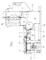
- the folding apparatus shown in FIG. 1 enables the production of folding products with two longitudinal folds and one transverse fold.
- the basic structure and the mode of operation of folding devices for the production of such products are known and therefore do not require any more detailed execution.
- the first longitudinal fold is carried out by means of a folding former 1, which can be attached to the frame of a printing press associated with the folding apparatus. Instead of the funnel fold, the web can of course also be cut open. Both options are referred to below as the first longitudinal fold.
- the web running from the hopper 1 is drawn into the folder via pulling rollers 2 and divided into successive sections in a manner known per se, which are provided with a transverse fold and then with a second longitudinal fold.
- the folding processes can be facilitated by perforating the web.
- perforation rollers 3 are provided in the area of the folder inlet.
- Three successive cylinders 4, 5, 6 are provided to form the cross-cutting and cross-folding devices.
- the middle cylinder 5 is provided with cutting grooves which cooperate with cutting blades arranged on the cylinder 4 placed thereon to form the cross section. In a manner known per se, the cutting grooves are associated with the punctures which are detected during the beginning of the path.
- the cylinder 5 is also provided with folding knives which cooperate with folding flaps arranged on the cylinder 6.
- the cylinder 4 is referred to below as the knife cylinder, the cylinder 5 as the puncture and folding knife cylinder and the cylinder 6 as the jaw cylinder.
- the folding knife cylinder 5 is from collective production to non-collected production switchable. Likewise, the speed of the cylinder forming the cross-cutting and cross-folding device and of the parts arranged downstream of it can be changed so that the cross-section can take place either over half the circumference or over the entire circumference.
- the folding jaw cylinder 6 is connected by a belt section 7 to a second longitudinal folding device 8, which here has a folding sword which interacts with folding rollers.
- the second longitudinal folding device 8 is penetrated by the belt section 7, which cooperates with the flap cylinder 6 on the input side and is provided with a delay device 9 in order to reduce the products fed to the second longitudinal folding device 8.
- sections of the belt section 7 are provided which are galvanized with one another and are driven at mutually graduated speeds in a manner known per se.
- the second longitudinal folding device 8 together with the tapes passing through it, ie. H.
- the belt section 7 is provided at one point with a further, non-galvanized subdivision 10.
- Below the folding rollers of the second longitudinal folding device 8 there is a delivery device with a paddle wheel 11 and a delivery belt 12 overlapped by it.
- the folding apparatus on which FIG. 1 is based is composed of two modules 13, 14 which are separate from one another and which here are attached directly to one another.
- the first module 13 comprises a base frame 15 arranged below the hopper 1 and containing the folder inlet with the pulling and perforating rollers 2, 3 and the cross-cutting and cross-folding devices with the cutting cylinder 4, the puncturing and folding knife cylinder 5 and the folding jaw cylinder 6 the entire height up to the former 1.
- the second module 14 consists of an additional frame 16 which extends approximately over half the height of the module 13 and which contains the belt section 7 and the second longitudinal folding device 8 and the delivery device associated therewith in the form of the paddle wheel 11 and the delivery belt 12.
- connection points 17, 18, here in the form of flat abutting surfaces In the expansion stage according to FIG. 1, these lie directly against one another.
- the connection can be made by detachable screws.
- connection point 17 of the base frame 15 assigned to the additional frame 16 is located in the region of the lower frame half.
- the folding jaw cylinder on the base frame is also located in this area 6 and the cooperating, additional frame-side band guide 7, which enables proper interaction.
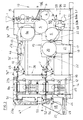
- a further module 19 can be inserted between the modules 13 and 14, as can be seen in FIG. 3, which shows the final stage of construction, which module consists of an intermediate frame 21 carrying a folding jaw cylinder 20, which has its lateral connection points 22 to the connection points facing one another 17, 18 of the base frame 15 or additional frame 16 connects.
- the folding jaw cylinder 6 on the base frame side is simultaneously equipped with folding knives.
- the original cylinder which is only equipped with jaws, can be replaced with a new cylinder.
- Another variant could consist in that the module 19 is penetrated by the belt section 7 and is provided with an upset folding device which interacts with it.
- the intermeshing cylinders 20 and 6 have different directions of rotation. These are chosen so that the cylinder 6 of the base frame 15 lying deeper with its delivery-side peripheral section downwards and the higher lying cylinder 20 of the additional frame with its delivery-side peripheral section upwards.
- a further module can be added in a further expansion stage, as can further be seen in FIG. 3, by attaching a mounting frame 23 containing a transverse fold extension device to the side of the additional frame 16 remote from the base frame.
- the additional frame 16 is provided with a connection point 24 in the region of its side remote from the base frame an associated connection point 25 of the mounting frame 23 fits together.
- the second longitudinal fold device 8 is of course passivated.
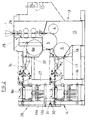
- FIG. 2 is based on a simple expansion stage of this type.
- a further module 26 is provided which is offset upwards from module 14.
- This includes an attachment frame 27 with a folder cylinder 6a forming a second transverse folding device together with the puncture and folding knife cylinder 5 on the base frame, which is connected by a belt section 7a to a downstream, second longitudinal folding device 8a, below which one is connected by a paddle wheel 11a with an associated delivery belt 12a located delivery device is arranged.
- the base frame 15 has an upper connection point 28 which is offset upwards relative to the connection point 17 and has a stepped configuration here, into which an assigned connection point 29 of the top frame 27 can engage.
- the base frame 16 overlapped by the top frame 27 is provided with a connection point 30 formed by a receiving surface, on which the top frame 27 can be placed with a connection point 31 formed by a corresponding storage surface.
- the stacking frame 27 is designed such that the second longitudinal folding devices 8, 8a are located one above the other, each with an associated delivery device.
- the top frame 27 can in turn be composed of several parts.
- the module 26 is composed of two parts, one of which practically corresponds to the module 14 located underneath and the other part contains the jaw cylinder 6a.
- the mutual butt joint 32 of the two parts of the module 26 is practically aligned with the butt joint underneath between the connection points 17, 18 of the base frame 15 and the additional frame 16.
- the two jaw cylinders 6, 6a are arranged one above the other or with a slight offset and are at 120 ° am
- the circumference of the folding knife cylinder 5 is offset from one another.
- each second longitudinal folding device 8, 8a is arranged downstream of an associated delivery device.
- the products obtained in the area of both second longitudinal folding devices 8, 8a can be introduced into one and the same paddle wheel, which facilitates further processing.
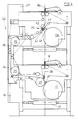
- the module 33 on which FIG. 4 is based can be provided for this purpose.
- This contains a side frame 34 which laterally bridges the additional frame 16 and the add-on frame 27, on which deflection members 35 of a band guide 36 are received, which has an approximately C-shaped configuration leading from the upper second longitudinal folding device 8a to the lower second longitudinal folding device 8.
- the additional frame 16 and the add-on frame 27 are provided with side connection points assigned to the side frame 34.
- the products coming from the upper and from the lower second longitudinal folding device are inserted into the paddle wheel 11 at the same point.
- a comparatively large deflection roller 37 is provided on the side above the impeller 11, around which a set of belts of a lower section of the belt section 36 runs and the set of belts closer to the other band set of the belt section 36 and downstream thereof from the center of the paddle wheel 11 the deduction from the folding rollers the lower second longitudinal folding device 8 ensuring band section 38 is affected.
- the other set of belts of the belt section 38 ends above the deflecting roller 37 or the belt set of the belt section 36 tangent to it.
- the belts of an upper section of the belt section 36 run around the latter to ensure reliable removal from the folding rollers of the upper second longitudinal folding device.
- the belt section 36 in the area above the paddle wheel 11a can be provided with a switch 39 which is drawn by solid lines from a lead to the lower paddle wheel 11 Position in a leading to the upper paddle wheel 11a, drawn with dashed lines position is switchable.
- the switch 39 here comprises two belt rollers 40, 41 which are received on a swivel frame.
- the set of belts of the belt section 36 facing away from the paddle wheel 11a passes through the switch 39 without interruption. This set of belts is engaged by the belt roller 40 facing away from the paddle wheel 11a.
- the other set of belts of the belt section 36 is interrupted in the area of the switch 39, the upper section being deflected around the roller 41 opposite the roller 40.
- the bottom section is over one of the swiveling ones Deflection roller 41 deflected opposite stationary deflection roller 42 in the position drawn with solid lines.
- a continuous transport plane thus results in the area of the switch 39, so that the products reach the branch of the belt section 36 leading to the lower paddle wheel 11.
- the transport plane of the branch of the belt section 36 coming from the upper folding rollers is pivoted out of the transport plane of the branch of the belt section 36 below the stationary deflecting roller 42, so that the products into the lower paddle wheel 11a located below.
- a stationary belt roller 43 is arranged above the swiveling roller 40, 41, which facilitates deflection of the continuous belt set.
- the highest expansion stage on which the above-mentioned FIG. 3 is based differs from the intermediate expansion stage according to FIG. 2 u. a. characterized in that in the area of the lower working level between base frame 15 and additional frame 16 the intermediate frame 21, which forms the module 19 and is provided with the folding jaw cylinder 20, is inserted.
- the cylinder 6 on the base frame side cooperating with the folding jaw cylinder is provided with folding jaws and folding knives.
- the folding jaw cylinder located at this point in the basic configuration according to FIG. 1 is replaced by a corresponding combination cylinder.
- the replaced jaw cylinder can be used in this stage as jaw cylinder 6a of the attached module 26.
- the drive of the folding jaw cylinders 6a and 20 located outside the base frame 15 is removed from the drive of the respectively adjacent base frame cylinder.
- the cylinders on the base frame are driven in a manner known per se by the machine main drive.
- the intermediate frame 21 increases the distance of the additional frame 16 from the base frame 15 compared to the arrangements according to FIGS. 1 and 2. Accordingly, the top frame 27 is also lengthened.
- an intermediate piece 27c is inserted between the parts 27a, 27b of the stacking frame containing the folding jaw cylinder 6a or the second longitudinal folding device 8a, the length of which corresponds exactly to the length of the intermediate frame 21, so that the second longitudinal folding devices 8, 8a still cover one another are arranged.
- the belt section 7a connecting the upper folding jaw cylinder 6a with the downstream second longitudinal folding device 8a is through the intermediate piece 27c carried out.
- the intermediate piece 27c is provided with an edging folding device 44 cooperating with the belt section 7a, the upsetting shaft and rear squeezing roller being pivotable in such a way that the products transported by the belt section 7a can optionally be introduced into or passed past the upsetting shaft.
- the edging fold device 44 enables the production of a second transverse fold in the area of the upper working level. It would also be conceivable to also provide a compression fold device of the type indicated at 44 for producing a second or further transverse fold in the region of the lower working level. This could be accommodated on the intermediate frame 21, ie assigned to the module 19.
- the lower belt section 7 cooperated with the folding jaw cylinder 6 on the base frame side, like the upper belt section 7a cooperates with the folding jaw cylinder 6a on the mounting frame side, so that practically the same belt section designs and folding jaw cylinder designs result above and below.
- a section 7a ' which can be driven at variable speed is therefore inserted into the upper belt section 7a. This can be driven by means of a PIV transmission independently of the upstream or downstream sections 7a ′′, 7a ′′ ′′ at variable speed.
- the rear section 7a ′′ interacting with the jaw cylinder 6a runs at the cylinder peripheral speed.
- the front section 7a '' 'passing through the assigned second longitudinal folding device 8a runs at a fixed ratio reduced or at the same speed as section 7a' '.
- the transfer of the products between the sections having different speeds takes place in the area of belt galvanizing 45 or 46, in a manner known per se.
- the interruption 10 required to ensure the lateral adjustability of the second longitudinal folding device 8a can be provided in the area of the middle section 7a, which can be driven at variable speed his.
- a cross-fold laying device which can be activated as an alternative to the second longitudinal folding devices 8, 8a is provided and can be attached in the form of a further module 47.
- the module 47 consists of an add-on frame 23, which has already been mentioned above and can be attached to the additional frame 16 on the side facing away from the base frame 15 and a mounting frame 23 a that can be attached to the top frame 27 in the same way.
- a paddle wheel 48 is accommodated, which overlaps a delivery belt 49 and can be acted upon by means of a belt section 50 which bridges the two mounting points 23, 23a and is arranged in a falling manner.
- the belt section 50 has an upper entrance 51 aligned with the end of the upper second longitudinal folding device 8a, the upper belt section 7a and an lower entrance 52 aligned with the end of the belt section 7 passing through the lower second transverse folding device.
- To form a reliable product feed in the area of the entrances 51 and 52 each have a comparatively large diameter deflecting roller 53 which is wrapped by a set of belts of the belt section 50 and, together with a further set of belts of the belt section 50 adjacent to it, delimits an entry wedge.
- the set of belts guided around the upper deflecting roller 53 ends in the area above the lower deflecting roller 53.
- the set of belts resting on the upper deflecting roller 53 affects the lower deflecting roller 53 and, together with the band set guided around them, forms a paddle wheel side delimited by deflecting rollers 54 arranged above the impeller 48 Exit of the belt section 50.
- the belt set lying on the lower deflection roller 53 to form the entrance 52 ends in the contact area of the continuous belt set. This results in a reliable drawing in of the products of the two inputs 51, 52.
- the products drawn in via the upper input 51 and via the lower input 52 can be thrown into the paddle wheel 48 one after the other or in a superimposed state, the throw-in on in any case -and in the same place, which makes control easier.
- a further module 56 can be inserted into the installation space 55.
- the module 56 has a slide-in frame 57 which can be brought into position between the side walls of the base frame 15, corresponding connection points being present either in the region of the frame side walls or the foundation. In both cases, the module 56 is provided with a cutting cylinder 4 around the base frame led around strand of material fed.
- the base frame 15 is accordingly provided with deflecting rollers 58 comprising the cutting cylinders 4 or has the possibility of attaching such deflecting rollers.
- the strand of material fed to the module 56 is drawn in by means of a pulling device 59 on the module side, which in the case of FIG. 3 is formed by pull rollers which can be set against one another and in the case of FIG. 6 by a drawing-in belt.
- a puncture and folding knife cylinder 60 which is attached to the folding jaw cylinder 6 on the base frame side and to which a separate cutting cylinder 61 is assigned, is accommodated on the insertion frame 57.
- the puncture and folding jaw cylinder 60 consists in a manner known per se of a puncture part 60a and a folding knife part 60b.
- the drive is designed such that the puncture part 60a is driven from the puncture part and the folding knife part 60b from the folding knife part of the base frame-side puncture and folding knife cylinder 5.
- the base frame in the area of the installation space 55 there are two pinwheels 62 provided on the base frame, which are connected in terms of drive to the puncture part or folding knife part of the puncture and folding knife cylinder 5 on the base frame and to those with the puncture part 60a or Folding knife part 60b of the insert-side cylinder 60 connected spur gears 63 can be brought into engagement.
- the mutual connection points of base frame 15 and slide-in frame 57 are designed such that, in the connected position, there is a proper tooth engagement between the spur gears 62 and drive gears 63.
- a clear coupling could also be provided between the stub shafts opposite one another in the inserted position.
- the drive of the arrangement according to FIG. 6 can be accomplished in a similar way.
- the feed belt 59 is followed by an overcutting device 64 which interacts with a downstream pull belt 65, which practically enables a format variation.
- the cross cutting device 64 The web sections produced are not transferred to one of the cylinders on the base frame, but rather are laid out on a separate extension section 66 arranged downstream of the take-off belt 65, which can adjoin the delivery belts 12 or 49.
- the delivery section 66 is driven correspondingly slower than the take-off belt running with a slight advance relative to the web speed.
- a brake roller 66a is provided which is assigned to the delivery section and swings up and down in time with the incoming products.
- a further module 67 can be provided with a mobile mounting frame 68 which can be adjusted from the rear to the base frame 16 and which partially engages in the installation space 55.
- This mounting frame 68 also has its own traction device 59 with its own cross-cutting device 64 and this downstream pulling belt 65.
- the delivery belt 69 connects to the delivery section 66, already mentioned in connection with FIG. 6, which passes under the lower working plane and which here passes to the delivery belt-side delivery belt 12, which in turn transfers to the extension frame-side delivery belt 49.
- the successive belts are fixed at different heights and are pivotally arranged so that they can be brought into and out of mutual engagement.
- the drive of the module 67 can simply be derived from the base rollers 2 on the base frame by bridging shaft stubs which are in alignment in the working position by a coupling piece.
- the module 67 or 56 can preferably be supplied with the entire web running over the hopper 1 or only a strand split off from it. If, as is to be preferred, the entire material web runs over the module 67 or 56, the folder drive downstream of the feed rollers 2 can be switched off.
Claims (10)
- Dispositif de pliage à structure modulaire, avec un module de base (13) qui contient un bâti de base (15) sur lequel est reçu un mécanisme de coupe transversale et de pliage transversal qui fait suite à un premier mécanisme de pliage longitudinal (1) et est équipé d'un cylindre de coupe (4), d'un cylindre à pointes et à plioirs (5) et d'un cylindre à volets plieurs (6) ; avec au moins un autre module (14), qui est associé à un plan de travail inférieur et qui contient un bâti auxiliaire (16), disposé sur le même niveau que le bâti de base (15), présentant un point de raccordement (18) tourné vers le point de raccordement (17) du bâti de base, et sur lequel est reçu un second mécanisme de plage longitudinal (8) traversé par un parcours associé de bandes (7) et suivi d'un mécanisme de sortie (11, 12) ; avec au moins un module supplémentaire (26), qui est associé à un plan de travail supérieur et qui présente un bâti rapporté (27) contenant un autre second mécanisme de pliage longitudinal (8a) avec un parcours associé de bandes supérieur (7a), le bâti auxiliaire (16) et le bâti rapporté (27) étant munis, dans la région de leurs seconds mécanismes de pliage longitudinal (8, 8a), de surfaces d'appui en vis-à-vis ; et avec au moins un autre module supplémentaire (47), qui présente un bâti annexe (23a) pouvant être rapporté sur le côté éloigné du bâti de base d'au moins un module précédent et recevant au moins un mécanisme de sortie de pliage transversal qui peut être activé en alternance avec les seconds mécanismes de pliage longitudinal (8, 8a), caractérisé en ce que le bâti auxiliaire (16) se trouve plus bas que le bâti de base (15), qui présente un point de raccordement supérieur (28) associé au bâti rapporté (27) et dont le point de raccordement inférieur (17) se trouve dans la région du cylindre à volets plieurs (6) du bâti de base, qui est disposé plus bas que le cylindre à pointes et à plioirs (5) qui coopère avec lui, se trouve dans la région du point de raccordement supérieur (28) et coopère également avec un cylindre à volets plieurs supplémentaire (6a) du bâti rapporté (27) qui précède le parcours de bandes supérieur (7a), et en ce que le bâti auxiliaire (16) et le bâti rapporté (27) sont munis, sur leur côté éloigné du bâti de base, de points de raccordement superposés (24) pour un bâti annexe respectif (23, 23a) qui est muni d'au moins un mécanisme de sortie de pliage transversal qui peut être activé en alternance avec les seconds mécanismes de pliage longitudinal (8, 8a).
- Dispositif de pliage selon la revendication 1, caractérisé en ce que le bâti rapporté (27) est constitué de plusieurs parties (27a, 27b, 27c) qui présentent des points de raccordement en vis-à-vis, qui sont alignés avec les points de raccordement des bâtis qui se trouvent en dessous.
- Dispositif de pliage selon l'une des revendications précédentes, caractérisé en ce qu'un bâti intermédiaire (21), présentant des points de raccordement correspondants, peut être introduit entre les points de raccordement en vis-à-vis (17, 18) du bâti de base (15) et du bâti auxiliaire (16), et porte un mécanisme pour réaliser au moins un pliage transversal supplémentaire, et en ce que le bâti rapporté (27) du second mécanisme de pliage longitudinal supérieur peut être prolongé par un élément intermédiaire (27c) qui présente la même longueur que le bâti intermédiaire (21) qui se trouve en dessous, élément qui est traversé par le parcours de bandes (7a) qui est muni d'un tronçon (7a') qui peut être entraîné à vitesse variable, qui présente de préférence deux tronçons parties se raccordant l'un à l'autre sans assemblage en queue d'aronde et se déplaçant à des vitesses identiques, et qui est assemblé en queue d'aronde, du côté d'entrée à un tronçon (7a''') coopérant avec le cylindre à volets plieurs (6a) disposé en amont, et du côté de sortie à un tronçon (7a''') traversant le second mécanisme de pliage longitudinal associé (8a), le tronçon (7a''') pouvant de préférence être entraîné à une vitesse réduite de moitié par rapport à celle du tronçon (7a'') du côté d'entrée.
- Dispositif de pliage selon l'une des revendications précédentes, caractérisé en ce que le bâti intermédiaire (21) porte un cylindre à volets plieurs (20) qui peut être amené en engagement avec le parcours de bandes (7) traversant le second mécanisme de pliage longitudinal (8) monté en aval et avec le cylindre à volets plieurs du bâti de base qui est monté en amont et qui est muni de plioirs supplémentaires, le cylindre à volets plieurs d'origine (6) du bâti de base pouvant être remplacé par un cylindre combiné muni de volets plieurs et de plioirs, et pouvant être utilisé comme cylindre à volets plieurs (6a) reçu sur le bâti rapporté (27).
- Dispositif de pliage selon l'une des revendications précédentes, caractérisé en ce qu'il est prévu, dans la région du parcours de bandes (7 ou 7a), un mécanisme de pliage à poches (44) qui est reçu sur l'élément intermédiaire (27c) ou selon le cas sur le bâti intermédiaire (21) et qui peut, de préférence, être enclenché et désenclenché.
- Dispositif de pliage selon l'une des revendications précédentes, caractérisé en ce qu'il est prévu un mécanisme de sortie de pliage transversal qui peut être alimenté par deux parcours de bandes (7, 7a) traversant respectivement le second mécanisme de pliage longitudinal supérieur ou inférieur (8, 8a), qui peut être activé en alternance avec les seconds mécanismes de pliage longitudinal (8, 8a) et qui présente une roue à palettes (48) recouvrant une bande de sortie (49) et reçu sur le bâti annexe inférieur (23), laquelle peut être alimentée à l'aide d'un parcours de bandes (50) disposé en chute verticale, qui présente une entrée supérieure (51), prévue dans la région d'un cylindre déflecteur (53) reçu sur le bâti annexe supérieur (23a) et alignée avec l'extrémité du parcours de bandes (7a) qui traverse le second mécanisme de pliage longitudinal supérieur (8a), et une entrée inférieure (52), prévue dans la région d'un cylindre déflecteur (53) reçu sur le bâti annexe inférieur (23) et alignée avec l'extrémité du parcours de bandes (7) qui traverse le second mécanisme de pliage longitudinal inférieur (8).
- Dispositif de pliage selon l'une des revendications précédentes, caractérisé en ce qu'il est prévu, sur le bâti auxiliaire (16) et le bâti rapporté (27), un bâti latéral (34) qui peut être rapporté latéralement et qui est destiné à recevoir des cylindres déflecteurs (35) d'un mécanisme de transfert qui est constitué par un parcours de bandes (36) approximativement en forme de C et qui mène des cylindres de pliage du second mécanisme de pliage longitudinal supérieur (8a) à une roue à palettes (11) qui est disposée à la suite des cylindres de pliage du second mécanisme de pliage longitudinal inférieur (8) et qui recouvre une bande de sortie (12), l'ensemble de bandes, le plus proche du centre de la roue à palettes (11), d'un parcours de bandes (38) disposé en chute verticale, menant à la roue à palettes (11) et faisant suite aux cylindres de pliage du second mécanisme de pliage longitudinal inférieur (8), étant tangent à un cylindre déflecteur (37), disposé au-dessus de la roue à palettes (11), qui est tangent, en amont, à un ensemble de bandes du parcours de bandes (36) constituant le mécanisme de transfert et qui est de préférence entouré par un ensemble de bandes du parcours de bandes (36) constituant le mécanisme de transfert.
- Dispositif de pliage selon la revendication 7, caractérisé en ce qu'une roue à palettes respective (11, 11a) est disposée à la suite des cylindres de plage des seconds mécanismes de pliage longitudinal supérieur et inférieur (8, 8a ), et en ce qu'il est prévu, au-dessus de la roue à palettes supérieure désenclenchable (11a), un mécanisme d'aiguillage (39) à l'aide duquel le parcours de bandes (36) constituant le mécanisme de transfert peut être commuté d'une position alimentant la roue à palettes supérieure (11a) à une position menant à roue à palettes inférieure (11) et vice-versa, et qui présente de préférence deux cylindres à bandes (40, 41) montés pivotants, le cylindre à bande (41) le plus proche du centre de la roue à palettes supérieure voisine (11a) déviant un ensemble de bandes, se terminant au-dessus de la roue à palettes supérieure (11a), du mécanisme de transfert provenant des cylindres de plage du second mécanisme de pliage longitudinal supérieur (8a), l'autre ensemble de bandes de ce mécanisme de transfert étant amené devant la roue à palettes supérieure (11a) et étant engagé par l'arrière par l'autre cylindre à bande (40), un cylindre déflecteur stationnaire (43), qui engage par l'arrière les deux ensembles de bandes, étant prévu au-dessus des cylindres à bandes pivotants (40, 41), et un cylindre déflecteur stationnaire (42), qui s'applique contre l'ensemble de bandes ininterrompu et qui reçoit le tronçon inférieur de l'ensemble de bandes interrompu, étant prévu en dessous des cylindres à bandes pivotants (40, 41).
- Dispositif de pliage selon l'une des revendications précédentes, caractérisé en ce que le bâti de base (15) peut être équipé de cylindres déflecteurs (58) constituant un guidage de parcours tournant autour du cylindre de coupe (4), et un bâti encastrable (57) peut être inséré dans un logement en forme de chambre (55) en dessous de l'ensemble de cylindres, bâti qui présente un mécanisme de traction (59) suivi d'un mécanisme de coupe transversale.
- Dispositif de pliage selon la revendication 9, caractérisé en ce que le bâti encastrable (57) présente un cylindre à pointes et à plioirs (60) qui peut être appliqué contre le cylindre à volets plieurs (6) du bâti de base et auquel est associé un cylindre de coupe (61), et dont la partie à pointes (60a) peut être entraînée par la partie à pointes du cylindre à pointes et à plioirs (5) du bâti de base, tandis que sa partie à plioirs (60b) peut être entraînée par la partie à plioirs du cylindre (5), ou en ce qu'un bâti encastrable (68), qui s'engage au moins partiellement dans le logement (55), peut être appliqué contre le bâti de base (15) et présente un mécanisme de coupe transversale (64) précédé d'un mécanisme de traction (50) et suivi d'un mécanisme de sortie qui, de préférence, entoure une roue à palettes (70) recouvrant une bande de sortie (69), les éléments du bâti encastrable (68) pouvant être entraînés à l'aide d'un tronçon d'arbre qui peut être aligné avec un tronçon d'entraînement du bâti de base.
Applications Claiming Priority (2)
| Application Number | Priority Date | Filing Date | Title |
|---|---|---|---|
| DE3626287 | 1986-08-02 | ||
| DE3626287A DE3626287C3 (de) | 1986-08-02 | 1986-08-02 | Falzapparat |
Publications (4)
| Publication Number | Publication Date |
|---|---|
| EP0256333A2 EP0256333A2 (fr) | 1988-02-24 |
| EP0256333A3 EP0256333A3 (en) | 1989-07-26 |
| EP0256333B1 EP0256333B1 (fr) | 1991-05-29 |
| EP0256333B2 true EP0256333B2 (fr) | 1995-04-12 |
Family
ID=6306611
Family Applications (1)
| Application Number | Title | Priority Date | Filing Date |
|---|---|---|---|
| EP87110518A Expired - Lifetime EP0256333B2 (fr) | 1986-08-02 | 1987-07-21 | Dispositif de pliage |
Country Status (4)
| Country | Link |
|---|---|
| US (1) | US4861326A (fr) |
| EP (1) | EP0256333B2 (fr) |
| JP (1) | JP2788238B2 (fr) |
| DE (2) | DE3626287C3 (fr) |
Cited By (1)
| Publication number | Priority date | Publication date | Assignee | Title |
|---|---|---|---|---|
| DE10121941C1 (de) * | 2001-05-05 | 2002-10-10 | Koenig & Bauer Ag | Falzvorrichtung |
Families Citing this family (37)
| Publication number | Priority date | Publication date | Assignee | Title |
|---|---|---|---|---|
| DE3904074A1 (de) * | 1989-02-11 | 1990-08-16 | Frankenthal Ag Albert | Falzapparat |
| US6125758A (en) * | 1992-03-13 | 2000-10-03 | K.K. Tokyo Kikai Seisakusho | Method for varying the piling-order and/or turning webs upside down in a rotary press |
| DE4208353A1 (de) * | 1992-03-16 | 1993-09-23 | Heidelberger Druckmasch Ag | Rotationsfalzapparat mit spezieller zylinderanordnung fuer rollenrotationsdruckmaschinen |
| DE4241810C2 (de) * | 1992-12-11 | 2001-01-04 | Heidelberger Druckmasch Ag | Formatvariabler Kombinationsfalzapparat |
| JP3197974B2 (ja) * | 1993-03-19 | 2001-08-13 | 東芝機械株式会社 | 可変サイズ折機 |
| US5405127A (en) * | 1993-04-14 | 1995-04-11 | Didde Web Press Corporation | Signature folder apparatus for web fed printing press with sheet stop adjustment |
| DE4327278C5 (de) * | 1993-08-13 | 2005-09-22 | Maschinenfabrik Wifag | Traggestell für eine Rollenrotationsdruckmaschine |
| DE4327466A1 (de) * | 1993-08-16 | 1995-02-23 | Roland Man Druckmasch | Vorrichtung zum Querperforieren |
| DE4332792C2 (de) * | 1993-09-27 | 2000-06-29 | Zirkon Druckmaschinen Gmbh | Falzapparat einer Rollenrotationsdruckmaschine |
| DE19507862A1 (de) * | 1995-03-08 | 1996-09-12 | Roth & Weber Ohg | Faltmaschine |
| DE19509947C2 (de) * | 1995-03-18 | 2002-12-05 | Koenig & Bauer Ag | Falzapparat für eine Rotationsdruckmaschine |
| DE19525169C2 (de) * | 1995-03-18 | 2000-02-03 | Koenig & Bauer Ag | Verfahren zum Antreiben eines Falzapparates |
| FR2733453B1 (fr) * | 1995-04-28 | 1997-07-25 | Heidelberg Harris Sa | Plieuse comprenant un module additionnel delivrant des cahiers |
| DE19516445A1 (de) * | 1995-05-04 | 1996-11-07 | Wifag Maschf | Rotationsdruckmaschine mit frei aufstellbarem Falzapparat |
| JP3835933B2 (ja) | 1998-02-27 | 2006-10-18 | 三菱重工業株式会社 | 折機の折り丁搬送装置 |
| DE19959152A1 (de) * | 1999-12-08 | 2001-06-13 | Heidelberger Druckmasch Ag | Einrichtung zur Führung von Materialbahnen in Rotationsdruckmaschinen |
| US6645134B2 (en) * | 2001-09-12 | 2003-11-11 | Vijuk Equipment, Inc. | Outsert-forming apparatus |
| US6656103B1 (en) | 2000-11-28 | 2003-12-02 | Vijuk Equipment, Inc. | Informational item forming machine and method |
| DE10116346B4 (de) * | 2001-04-02 | 2006-03-02 | Koenig & Bauer Ag | Falzapparat |
| DE10128122A1 (de) * | 2001-06-09 | 2002-12-12 | Roland Man Druckmasch | Antrieb für einen Falzapparat |
| ITMI20011800A1 (it) * | 2001-08-17 | 2003-02-17 | Studio Design S A S Di Stefano | Macchina per la produzione di materiale flessibile in fogli |
| RU2217369C1 (ru) * | 2002-12-20 | 2003-11-27 | Джермакян Карен Юрьевич | Машина для формирования марлевых салфеток |
| GB0315986D0 (en) * | 2003-07-08 | 2003-08-13 | Goss Graphic Systems Ltd | Printing press |
| ATE375863T1 (de) * | 2003-07-08 | 2007-11-15 | Goss Graphic Systems Ltd | Druckmaschine |
| ES2344895T3 (es) * | 2004-08-31 | 2010-09-09 | M T C - Macchine Trasformazione Carta S.R.L. | Estructura de una maquina de plegado. |
| US7175586B2 (en) * | 2005-03-21 | 2007-02-13 | Vijuk Equipment, Inc. | Methods of forming outserts |
| DE102005039395A1 (de) * | 2005-08-20 | 2007-02-22 | Man Roland Druckmaschinen Ag | Falzapparat einer Rollendruckmaschine |
| ES2333740T3 (es) * | 2006-02-28 | 2010-02-26 | M T C - Macchine Trasformazione Carta S.R.L. | Maquina de interplegado modular que permite un cambio de formato simple. |
| US20070207910A1 (en) * | 2006-03-03 | 2007-09-06 | Vijuk Equipment, Inc. | Outsert-forming machine and method |
| ITBO20060291A1 (it) | 2006-04-14 | 2007-10-15 | Tech S R L S | Apparecchiatura per la piegatura ordinata di nastri. |
| DE102006039981B3 (de) * | 2006-08-25 | 2008-01-31 | Koenig & Bauer Aktiengesellschaft | Falzapparat |
| EP2259924B1 (fr) | 2008-03-27 | 2014-01-01 | Pressline Services, Inc | Procédés de fonctionnement d'une presse d impression |
| DE102008032621A1 (de) * | 2008-05-27 | 2009-12-03 | Manroland Ag | Vorrichtung zur Herstellung längsgefalzter Produkte |
| US20120165174A1 (en) * | 2010-12-23 | 2012-06-28 | C.G. Bretting Manufacturing Co., Inc. | Single web single-fold apparatus and method |
| US9371209B2 (en) | 2012-05-01 | 2016-06-21 | C.G. Bretting Manufacturing Co., Inc. | Single path single web single-fold interfolder and methods |
| US10363766B2 (en) | 2013-03-15 | 2019-07-30 | G&K-Vijuk Intern. Corp. | Information item forming machine with visual inspection unit and method for forming and sorting informational items |
| US10449746B2 (en) | 2016-06-27 | 2019-10-22 | C. G. Bretting Manufacturing Co., Inc. | Web processing system with multiple folding arrangements fed by a single web handling arrangement |
Family Cites Families (13)
| Publication number | Priority date | Publication date | Assignee | Title |
|---|---|---|---|---|
| US974231A (en) * | 1906-10-01 | 1910-11-01 | John A Boyce | Apparatus for printing and folding papers. |
| US2253446A (en) * | 1938-03-28 | 1941-08-19 | Spiess Georg | Buckling folding machine |
| US3008707A (en) * | 1958-07-21 | 1961-11-14 | Liberty Folder Company | Method and means for production of signatures |
| DE1204689B (de) * | 1962-03-16 | 1965-11-11 | Koenig & Bauer Schnellpressfab | Querfalzapparat an Rollen-Rotationsdruckmaschinen |
| JPS5019971B1 (fr) * | 1970-01-14 | 1975-07-11 | ||
| US4167265A (en) * | 1976-10-21 | 1979-09-11 | Graphics Equipment International Corporation | Folding machine and control |
| US4159823A (en) * | 1977-08-12 | 1979-07-03 | Wood Industries, Inc. | Multiple product folder |
| CH628855A5 (fr) * | 1978-04-03 | 1982-03-31 | Fobelmac Sprl | Procede pour acheminer et traiter ou travailler en continu une bande souple pour produire des documents et installation pour sa mise en oeuvre. |
| JPS54154622A (en) * | 1978-05-26 | 1979-12-05 | Toshiba Mach Co Ltd | Paper folding apparatus for rotary press |
| FR2437938A1 (fr) * | 1978-10-03 | 1980-04-30 | Marinoni | Mecanisme pour plieuse d'imprimerie |
| JPS5711818A (en) * | 1980-06-20 | 1982-01-21 | Mitsubishi Heavy Ind Ltd | Novel crystalline silicate and its preparation |
| DD159252A3 (de) * | 1981-06-23 | 1983-03-02 | Kurt Sehan | Falzapparat fuer rollenrotationsdruckmaschinen |
| DE3422755C2 (de) * | 1984-06-20 | 1986-06-19 | Koenig & Bauer AG, 8700 Würzburg | Falzapparat für Buchfalzungen an einer Rollenrotationsdruckmaschine |
-
1986
- 1986-08-02 DE DE3626287A patent/DE3626287C3/de not_active Expired - Fee Related
-
1987
- 1987-07-14 US US07/073,183 patent/US4861326A/en not_active Expired - Fee Related
- 1987-07-21 DE DE8787110518T patent/DE3770364D1/de not_active Expired - Fee Related
- 1987-07-21 EP EP87110518A patent/EP0256333B2/fr not_active Expired - Lifetime
- 1987-08-01 JP JP62193636A patent/JP2788238B2/ja not_active Expired - Lifetime
Cited By (1)
| Publication number | Priority date | Publication date | Assignee | Title |
|---|---|---|---|---|
| DE10121941C1 (de) * | 2001-05-05 | 2002-10-10 | Koenig & Bauer Ag | Falzvorrichtung |
Also Published As
| Publication number | Publication date |
|---|---|
| EP0256333A3 (en) | 1989-07-26 |
| DE3626287C3 (de) | 1997-04-03 |
| JP2788238B2 (ja) | 1998-08-20 |
| DE3770364D1 (de) | 1991-07-04 |
| DE3626287C2 (fr) | 1993-03-18 |
| DE3626287A1 (de) | 1988-02-04 |
| JPS6341378A (ja) | 1988-02-22 |
| US4861326A (en) | 1989-08-29 |
| EP0256333A2 (fr) | 1988-02-24 |
| EP0256333B1 (fr) | 1991-05-29 |
Similar Documents
| Publication | Publication Date | Title |
|---|---|---|
| EP0256333B2 (fr) | Dispositif de pliage | |
| EP1110724B1 (fr) | Dispositif pour enfiler une bande de papier | |
| EP0481172B1 (fr) | Rotative d'impression pour l'impression de livres et de calandriers, avec deux dispositifs de pliage longitudinal | |
| DE2823247C2 (de) | Einrichtung zur Umlenkung eines aus bogenförmigen Produkten bestehenden Produktstroms | |
| EP0586970B1 (fr) | Dispositif de pliage pour machine à imprimer rotative pour bandes | |
| EP1524227B1 (fr) | Procédé d'utilisation d'un appareil de pliage | |
| DE4208353A1 (de) | Rotationsfalzapparat mit spezieller zylinderanordnung fuer rollenrotationsdruckmaschinen | |
| CH687245A5 (de) | Einrichtung zum Foerdern und Trennen von gefalteten Druckprodukten. | |
| EP0205116B1 (fr) | Plieuse | |
| EP0820949A1 (fr) | Dispositif de guidage de cahiers à la sortie d'un groupe de deux cylindres coupeurs d'une plieuse | |
| CH693631A5 (de) | Anordnung zum Zusammenführen von Bedruckstoffbahnen vor einem Längsfalztrichter. | |
| EP1062176A1 (fr) | Cone plieur | |
| DE3520963C2 (fr) | ||
| EP1401749A1 (fr) | Procede et dispositif de regroupage de bandes de materiau | |
| DE10059587A1 (de) | Verfahren und Vorrichtung zum Falzen von Materialbogen | |
| DE4035106A1 (de) | Falzmaschine | |
| DE102006039981B3 (de) | Falzapparat | |
| EP4178898A1 (fr) | Plieuse comprenant un groupe de pliage à lame et procédé de pliage de produits à plier au moyen d'un groupe de pliage à lame | |
| DE19650800C2 (de) | Taschenfalzmaschine | |
| DE3737139C1 (en) | Device for folding and cutting small-size in-line products to be folded | |
| EP0922662A1 (fr) | Dispositif pour le traitement de la bande de papier d'une machine rotative d'impressions | |
| DE19649294C2 (de) | Falzapparat zur Herstellung von Buchsektionen |
Legal Events
| Date | Code | Title | Description |
|---|---|---|---|
| PUAI | Public reference made under article 153(3) epc to a published international application that has entered the european phase |
Free format text: ORIGINAL CODE: 0009012 |
|
| AK | Designated contracting states |
Kind code of ref document: A2 Designated state(s): CH DE FR GB IT LI NL SE |
|
| PUAL | Search report despatched |
Free format text: ORIGINAL CODE: 0009013 |
|
| AK | Designated contracting states |
Kind code of ref document: A3 Designated state(s): CH DE FR GB IT LI NL SE |
|
| 17P | Request for examination filed |
Effective date: 19890621 |
|
| 17Q | First examination report despatched |
Effective date: 19901119 |
|
| GRAA | (expected) grant |
Free format text: ORIGINAL CODE: 0009210 |
|
| AK | Designated contracting states |
Kind code of ref document: B1 Designated state(s): CH DE FR GB IT LI NL SE |
|
| ITF | It: translation for a ep patent filed |
Owner name: DR. ING. AUSSERER ANTON |
|
| GBT | Gb: translation of ep patent filed (gb section 77(6)(a)/1977) | ||
| REF | Corresponds to: |
Ref document number: 3770364 Country of ref document: DE Date of ref document: 19910704 |
|
| ET | Fr: translation filed | ||
| PLBI | Opposition filed |
Free format text: ORIGINAL CODE: 0009260 |
|
| 26 | Opposition filed |
Opponent name: MAN ROLAND DRUCKMASCHINEN AG Effective date: 19920214 |
|
| NLR1 | Nl: opposition has been filed with the epo |
Opponent name: MAN ROLAND DRUCKMASCHINEN AG |
|
| EAL | Se: european patent in force in sweden |
Ref document number: 87110518.5 |
|
| PUAH | Patent maintained in amended form |
Free format text: ORIGINAL CODE: 0009272 |
|
| STAA | Information on the status of an ep patent application or granted ep patent |
Free format text: STATUS: PATENT MAINTAINED AS AMENDED |
|
| ITF | It: translation for a ep patent filed |
Owner name: DR. ING. AUSSERER ANTON |
|
| 27A | Patent maintained in amended form |
Effective date: 19950412 |
|
| AK | Designated contracting states |
Kind code of ref document: B2 Designated state(s): CH DE FR GB IT LI NL SE |
|
| GBTA | Gb: translation of amended ep patent filed (gb section 77(6)(b)/1977) |
Effective date: 19950412 |
|
| REG | Reference to a national code |
Ref country code: CH Ref legal event code: AEN |
|
| NLR2 | Nl: decision of opposition | ||
| ET3 | Fr: translation filed ** decision concerning opposition | ||
| NLR3 | Nl: receipt of modified translations in the netherlands language after an opposition procedure | ||
| PGFP | Annual fee paid to national office [announced via postgrant information from national office to epo] |
Ref country code: DE Payment date: 19990927 Year of fee payment: 13 |
|
| PGFP | Annual fee paid to national office [announced via postgrant information from national office to epo] |
Ref country code: GB Payment date: 20000704 Year of fee payment: 14 |
|
| PGFP | Annual fee paid to national office [announced via postgrant information from national office to epo] |
Ref country code: FR Payment date: 20000717 Year of fee payment: 14 |
|
| PGFP | Annual fee paid to national office [announced via postgrant information from national office to epo] |
Ref country code: NL Payment date: 20000718 Year of fee payment: 14 |
|
| PGFP | Annual fee paid to national office [announced via postgrant information from national office to epo] |
Ref country code: SE Payment date: 20000720 Year of fee payment: 14 |
|
| PGFP | Annual fee paid to national office [announced via postgrant information from national office to epo] |
Ref country code: CH Payment date: 20000802 Year of fee payment: 14 |
|
| PG25 | Lapsed in a contracting state [announced via postgrant information from national office to epo] |
Ref country code: DE Free format text: LAPSE BECAUSE OF NON-PAYMENT OF DUE FEES Effective date: 20010501 |
|
| PG25 | Lapsed in a contracting state [announced via postgrant information from national office to epo] |
Ref country code: GB Free format text: LAPSE BECAUSE OF NON-PAYMENT OF DUE FEES Effective date: 20010721 |
|
| PG25 | Lapsed in a contracting state [announced via postgrant information from national office to epo] |
Ref country code: SE Free format text: LAPSE BECAUSE OF NON-PAYMENT OF DUE FEES Effective date: 20010722 |
|
| PG25 | Lapsed in a contracting state [announced via postgrant information from national office to epo] |
Ref country code: LI Free format text: LAPSE BECAUSE OF NON-PAYMENT OF DUE FEES Effective date: 20010731 Ref country code: CH Free format text: LAPSE BECAUSE OF NON-PAYMENT OF DUE FEES Effective date: 20010731 |
|
| PG25 | Lapsed in a contracting state [announced via postgrant information from national office to epo] |
Ref country code: NL Free format text: LAPSE BECAUSE OF NON-PAYMENT OF DUE FEES Effective date: 20020201 |
|
| EUG | Se: european patent has lapsed |
Ref document number: 87110518.5 |
|
| GBPC | Gb: european patent ceased through non-payment of renewal fee |
Effective date: 20010721 |
|
| REG | Reference to a national code |
Ref country code: CH Ref legal event code: PL |
|
| PG25 | Lapsed in a contracting state [announced via postgrant information from national office to epo] |
Ref country code: FR Free format text: LAPSE BECAUSE OF NON-PAYMENT OF DUE FEES Effective date: 20020329 |
|
| NLV4 | Nl: lapsed or anulled due to non-payment of the annual fee |
Effective date: 20020201 |
|
| REG | Reference to a national code |
Ref country code: FR Ref legal event code: ST |
|
| PG25 | Lapsed in a contracting state [announced via postgrant information from national office to epo] |
Ref country code: IT Free format text: LAPSE BECAUSE OF NON-PAYMENT OF DUE FEES;WARNING: LAPSES OF ITALIAN PATENTS WITH EFFECTIVE DATE BEFORE 2007 MAY HAVE OCCURRED AT ANY TIME BEFORE 2007. THE CORRECT EFFECTIVE DATE MAY BE DIFFERENT FROM THE ONE RECORDED. Effective date: 20050721 |
|
| PLAB | Opposition data, opponent's data or that of the opponent's representative modified |
Free format text: ORIGINAL CODE: 0009299OPPO |