EP0250290B1 - Gelenk für Wagensitzrückenlehne oder ähnliche Verwendung, welches asymmetrisch geführte Schieber aufweist - Google Patents
Gelenk für Wagensitzrückenlehne oder ähnliche Verwendung, welches asymmetrisch geführte Schieber aufweist Download PDFInfo
- Publication number
- EP0250290B1 EP0250290B1 EP87401265A EP87401265A EP0250290B1 EP 0250290 B1 EP0250290 B1 EP 0250290B1 EP 87401265 A EP87401265 A EP 87401265A EP 87401265 A EP87401265 A EP 87401265A EP 0250290 B1 EP0250290 B1 EP 0250290B1
- Authority
- EP
- European Patent Office
- Prior art keywords
- pawls
- grains
- teeth
- toothed ring
- toothing
- Prior art date
- Legal status (The legal status is an assumption and is not a legal conclusion. Google has not performed a legal analysis and makes no representation as to the accuracy of the status listed.)
- Expired - Lifetime
Links
Images


Classifications
-
- B—PERFORMING OPERATIONS; TRANSPORTING
- B60—VEHICLES IN GENERAL
- B60N—SEATS SPECIALLY ADAPTED FOR VEHICLES; VEHICLE PASSENGER ACCOMMODATION NOT OTHERWISE PROVIDED FOR
- B60N2/00—Seats specially adapted for vehicles; Arrangement or mounting of seats in vehicles
- B60N2/02—Seats specially adapted for vehicles; Arrangement or mounting of seats in vehicles the seat or part thereof being movable, e.g. adjustable
- B60N2/22—Seats specially adapted for vehicles; Arrangement or mounting of seats in vehicles the seat or part thereof being movable, e.g. adjustable the back-rest being adjustable
- B60N2/235—Seats specially adapted for vehicles; Arrangement or mounting of seats in vehicles the seat or part thereof being movable, e.g. adjustable the back-rest being adjustable by gear-pawl type mechanisms
- B60N2/2356—Seats specially adapted for vehicles; Arrangement or mounting of seats in vehicles the seat or part thereof being movable, e.g. adjustable the back-rest being adjustable by gear-pawl type mechanisms with internal pawls
- B60N2/236—Seats specially adapted for vehicles; Arrangement or mounting of seats in vehicles the seat or part thereof being movable, e.g. adjustable the back-rest being adjustable by gear-pawl type mechanisms with internal pawls linearly movable
-
- B—PERFORMING OPERATIONS; TRANSPORTING
- B60—VEHICLES IN GENERAL
- B60N—SEATS SPECIALLY ADAPTED FOR VEHICLES; VEHICLE PASSENGER ACCOMMODATION NOT OTHERWISE PROVIDED FOR
- B60N2205/00—General mechanical or structural details
- B60N2205/20—Measures for elimination or compensation of play or backlash
Definitions
- the grains favor an increase in the number of positions of inclination of the seat back relative to a seat insofar as the fixed toothing of the movable crown and the toothing of the grains are very small.
- EP-A 0 023 863 discloses a seat back articulation device in which the fixed flange and the movable flange are both internally provided with teeth intended to cooperate simultaneously with toothed latches, for example at number of three, which are guided in their movement of radial translation by guides but with a certain friction.
- the radial movement of the latches is caused by inclined bosses of a central cam controlled by a lever with an operating button.
- this lever is subjected to the action of a spring tending to place the control in the position for which it pushes the locks on the periphery of the articulation mechanism to block the teeth of each of these locks in the corresponding teeth.
- fixed and mobile flanges are both internally provided with teeth intended to cooperate simultaneously with toothed latches, for example at number of three, which are guided in their movement of radial translation by guides but with a certain friction.
- the radial movement of the latches is caused by inclined bosses of a central cam controlled by a
- the present invention overcomes these drawbacks by creating a joint which allows a greater number of locking positions relative to the number of teeth produced on the fixed locking ring by the use of three grains and by the angular offset of a certain value of two of the grains thus permitting the penetration of the teeth of one of the grains at the bottom of the tooth of the locking crown and for the other two grains, a partial penetration of the teeth of the grains in the locking crown causing blocking without play of the joint in all positions with a very small angular offset equal to one third of the angle of each tooth of the locking crown.
- This solution also makes it possible to produce the teeth of the locking crown and of the grains by very rapid and cheaper methods because the angle of each tooth is large enough to allow the use of high-yield manufacturing methods since in any case the angular displacement is equal to Vs of the angle of each tooth since the joint always comprises at least three grains arranged to obtain the 360 ° of the circumference, which corresponds for the case to three grains at positions of 120 ° - a / s ; 120 ° + 2 / sa; 120 ° - a / 3 .
- EP-A 0 023 863 which describes an articulation for a vehicle seat backrest or similar applications comprising locking grains in which the fixed flange is shaped so as to guide, by means of sectors, three sliding grains whose pitch of the upper teeth corresponds to the pitch of the teeth of the toothed crown of the movable flange, these grains, normally pushed back from the teeth by elastic members, being angularly offset and subjected to the thrust of a control member such as a cam , is characterized in that the asymmetric angular offset of two grains with respect to the first grain is 120 ° -a / s, that is to say that the offset between the two other grains is 120 • + 2 / ⁇ a, a being the angle corresponding to the pitch of a tooth of the toothed crown or of the grains so that at least one of the grains penetrates fully into the toothed crown while the teeth of the other grains are supported partly on the opposite faces of the teeth of the ring gear, thereby ensuring a locking of the
- the toothed grains have narrower extensions tail shaped such that the extensions have a clearance of 0/3 with respect to opposite faces of the fixed flange sectors, grains further having at their upper part of the flared zones which cooperate with zones clear of the sectors of the fixed flange to allow, despite the angular offset of a / 3 of the two other grains relative to the first, their centering and their penetration into the ring gear of the fixed flange when '' they are pushed back by the cam control.
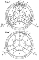
- FIG 1 there is shown schematically a fixed gear ring 1 come by stamping or fine cutting on the movable flange 2 of a vehicle seat back articulation.
- the angle a corresponds exactly to the angle of a tooth of this crown.
- the grains 3, 4, 5, which have a substantially square shape, have, at their upper ends 3a, 4a, 5a, teeth 6 having exactly the same angle a as the teeth of the crown 1.
- the rear part of the grains 3 , 4, 5 has a central surface 7 which cooperates with the control member, generally a cam.
- the grains 3, 4, 5 are guided in the fixed flange represented by sectors 8, 9, 10 integral with the fixed flange and which form, by their converging sides 8a, 8b, 9a, 9b, 10a, 10b, guides for the grains 3, 4, 5 but due to the construction, on the one hand, of sectors 8, 9, 10 and, on the other hand, of grains 3, 4, 5, grains 4 and 5 are arranged at 120 ° - ⁇ / 3 relative to the grain 3.
- the minimum displacement angle of the backrest relative to the seat can be equal to al three that is to say to one third of the angle of a tooth of the ring gear 1 and, if the angle a is small, of the order of 2 ° , a sensitivity of the order of 40 min is obtained which was impossible until now.
- the toothed crown 1 ′ of the movable flange 11 always employs teeth of very small angular pitch, for example 2 ° , which can easily be obtained by a technology perfectly developed such as fine cutting.
- the teeth 12 of the grains 13, 14, 15 obviously have the same pitch as the teeth of the crown 1 ' , but these grains have, at their rear part, two angular sides 13a, 13b, 14a, 14b, 15a, 15b allowing them , when pushed back (fig. 3), to center along the axis of their guide to be ready to penetrate the tooth of the crown 10.
- the guides are wider than the grains.
- the play is equivalent to a lateral displacement of an angle of a / ⁇ since, when the grains are pushed back in the teeth, they will take place according to the position of the crown 1, that is to say at an equidistant angle of 120 ° .
- the grains may, depending on the case, the angular positions of the crown 1 ′, bear on the faces of the semi-cut fixed flange 16 or 17 or 18.
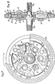
- the articulation is identical to the articulation described with reference to FIGS. 3 and 4 but the grains 13, 14 and 15 are of a lower height so that their lower part has a flat surface 13 ' , 14 ', 15' which comes to rest on the lower part of a substantially V-shaped clearance 21 provided at the upper part of an intermediate part 22, 23, 24. These intermediate parts are in contact through their lower zone 22a, 23a , 24a with the control member which is generally a cam. In the locking position, that is to say when the grains 13, 14, 15 are not in engagement with the toothed crown 1 ′, the grains occupy the position shown in FIG.
- FIGS. 7 and 8 a complete articulation is shown, the central control shaft 25 of which, in its chamfered part 25a, has the cam 26 having three nozzles 26a, 26b, 26c intended to cooperate with the intermediate parts 22, 23, 24 controlling the movement of the grains 13, 14, 15 as explained above.
- the segments 16, 17, 18 are shaped to allow, by recesses 27, the installation of springs 28 having in plan substantially the shape of a V which tends to push the cam 26 against the intermediate parts 22, 23, 24 in order to block the teeth of the grains at the bottom of the toothed crown 1 As is very visible in FIGS.
- the grains when they are at the bottom of the teeth, each deform an elastic return blade 29 so that these grains can be easily released from the ring gear 10 when the cam 26, having pivoted under the action of the central control shaft 25, allows the clearance, by rotation, of the nozzles 26a, 26b, 26c intermediate parts 22, 23, 24 thereby ensuring the release of the seat back relative to the seat of the latter.
- FIG. 8 it can be seen that the fixed flange 30, which carries fixing pins 31 to connect it to the seat, peripherally maintains a circular crown 32 which guides the movable flange 11 by means of guide stampings 33 visible both at Figure 7 than in Figure 8. It should also be noted that the movable flange 11 carries fixing pins 34 allowing it to be easily connected to the frame of the backrest. This fixation is moreover well known.
- the central shaft 25 has (see FIG. 8) a grooved end 25b for fixing the manual or motor control of the articulation while the grooved end 25c of this shaft 25 allows the connection for example by means of a hollow shaft between the two joint mechanisms placed on each side of the seat.
Landscapes
- Engineering & Computer Science (AREA)
- Aviation & Aerospace Engineering (AREA)
- Transportation (AREA)
- Mechanical Engineering (AREA)
- Chairs For Special Purposes, Such As Reclining Chairs (AREA)
- Seats For Vehicles (AREA)
- Chair Legs, Seat Parts, And Backrests (AREA)
- Clamps And Clips (AREA)
- Tyre Moulding (AREA)
- Vehicle Step Arrangements And Article Storage (AREA)
- Passenger Equipment (AREA)
- Preparation Of Compounds By Using Micro-Organisms (AREA)
- Heating, Cooling, Or Curing Plastics Or The Like In General (AREA)
- Processing And Handling Of Plastics And Other Materials For Molding In General (AREA)
- Yarns And Mechanical Finishing Of Yarns Or Ropes (AREA)
- Special Chairs (AREA)
Claims (3)
Priority Applications (1)
| Application Number | Priority Date | Filing Date | Title |
|---|---|---|---|
| AT87401265T ATE55573T1 (de) | 1986-06-06 | 1987-06-04 | Gelenk fuer wagensitzrueckenlehne oder aehnliche verwendung, welches asymmetrisch gefuehrte schieber aufweist. |
Applications Claiming Priority (2)
| Application Number | Priority Date | Filing Date | Title |
|---|---|---|---|
| FR8608211A FR2599684B1 (fr) | 1986-06-06 | 1986-06-06 | Articulations pour dossier de siege de vehicule ou applications analogues comportant des grains a guidages asymetriques |
| FR8608211 | 1986-06-06 |
Publications (2)
| Publication Number | Publication Date |
|---|---|
| EP0250290A1 EP0250290A1 (de) | 1987-12-23 |
| EP0250290B1 true EP0250290B1 (de) | 1990-08-16 |
Family
ID=9336095
Family Applications (1)
| Application Number | Title | Priority Date | Filing Date |
|---|---|---|---|
| EP87401265A Expired - Lifetime EP0250290B1 (de) | 1986-06-06 | 1987-06-04 | Gelenk für Wagensitzrückenlehne oder ähnliche Verwendung, welches asymmetrisch geführte Schieber aufweist |
Country Status (13)
| Country | Link |
|---|---|
| US (1) | US4770464A (de) |
| EP (1) | EP0250290B1 (de) |
| JP (1) | JPH01104201A (de) |
| CN (1) | CN1005141B (de) |
| AT (1) | ATE55573T1 (de) |
| CA (1) | CA1279252C (de) |
| DE (1) | DE3764321D1 (de) |
| DK (1) | DK291587A (de) |
| ES (1) | ES2016856B3 (de) |
| FR (1) | FR2599684B1 (de) |
| GR (1) | GR3000978T3 (de) |
| PT (1) | PT85021B (de) |
| YU (1) | YU46618B (de) |
Cited By (1)
| Publication number | Priority date | Publication date | Assignee | Title |
|---|---|---|---|---|
| DE102015216109A1 (de) | 2015-08-24 | 2017-03-02 | Sitech Sitztechnik Gmbh | Rastbeschlag mit einem Riegel mit Spielausgleich |
Families Citing this family (62)
| Publication number | Priority date | Publication date | Assignee | Title |
|---|---|---|---|---|
| GB8805290D0 (en) * | 1988-03-05 | 1988-04-07 | Ihw Eng Ltd | Seat reclining mechanism |
| CA1293682C (en) * | 1988-12-28 | 1991-12-31 | George Croft | Compact latching device for seat assemblies |
| US5161856A (en) * | 1990-03-17 | 1992-11-10 | Tachi-S Co., Ltd. | Reclining device for a seat |
| FR2673519B1 (fr) * | 1991-03-05 | 1993-12-24 | Faure Automobile Bertrand | Mecanisme de reglage du dossier d'un siege. |
| US5622407A (en) * | 1993-11-19 | 1997-04-22 | Aisin Seiki Kabushiki Kaisha | Seat apparatus |
| DE4419411C2 (de) * | 1994-06-03 | 1999-12-23 | Keiper Recaro Gmbh Co | Gelenkbeschlag für Fahrzeugsitze, insbesondere Kraftfahrzeugsitze |
| JP3289505B2 (ja) * | 1994-08-11 | 2002-06-10 | アラコ株式会社 | 車両用シートのリクライニング装置 |
| US5516198A (en) * | 1994-09-28 | 1996-05-14 | Tachi-S Co., Ltd. | Reclining device for vehicle seat |
| JPH10510496A (ja) * | 1994-12-14 | 1998-10-13 | カイパー レカロ ゲゼルシャフト ミット ベシュレンクテル ハフツング ウント コンパニー | 車両座席の接合取付け具 |
| EP0749865B1 (de) * | 1995-06-23 | 2001-11-21 | Fuji Kiko Co., Ltd. | Verstellbarer Drehgelenkbeschlag für neigungsverstellbare Sitze |
| EP0755824B1 (de) * | 1995-07-28 | 1999-09-22 | Keiper GmbH & Co. | Fahrzeugsitz |
| JP3080136B2 (ja) * | 1995-07-31 | 2000-08-21 | 池田物産株式会社 | 内歯式リクライニングデバイス |
| FR2740406B1 (fr) * | 1995-10-27 | 1998-01-02 | Faure Bertrand Equipements Sa | Articulation pour siege de vehicule |
| JP3080139B2 (ja) * | 1995-11-08 | 2000-08-21 | 池田物産株式会社 | 内歯式リクライニングデバイス |
| US5664837A (en) * | 1996-03-29 | 1997-09-09 | Tachi-S Co., Ltd. | Reclining device for vehicle seat |
| US5664836A (en) * | 1996-03-29 | 1997-09-09 | Tachi-S Co., Ltd. | Reclining device for vehicle seat |
| US6142569A (en) * | 1997-02-13 | 2000-11-07 | Nhk Spring Co., Ltd, | Reclining device |
| DE19814225B4 (de) * | 1997-04-03 | 2006-12-28 | Keiper Gmbh & Co.Kg | Lehneneinstellbeschlag |
| US6120098A (en) * | 1997-07-15 | 2000-09-19 | Magna Lomason Corporation | Ring-type recliner |
| JP3948086B2 (ja) * | 1997-12-02 | 2007-07-25 | アイシン精機株式会社 | シートリクライニング装置 |
| DE19816248C1 (de) * | 1998-04-11 | 1999-10-14 | Keiper Gmbh & Co | Lehneneinstellbeschlag für einen Fahrzeugsitz |
| JPH11299563A (ja) * | 1998-04-21 | 1999-11-02 | Fuji Kiko Co Ltd | 自動車用シートリクライニング装置のガタ防止方法及びその構造 |
| FR2792583B1 (fr) | 1999-04-20 | 2001-07-27 | Faure Bertrand Equipements Sa | Mecanisme d'articulation pour siege de vehicule |
| US6312053B1 (en) | 1999-07-20 | 2001-11-06 | Magna Interior Systems, Inc. | Recliner assembly |
| FR2806981B1 (fr) * | 2000-03-30 | 2002-06-14 | Faure Bertrand Equipements Sa | Mecanisme d'articulation pour siege de vehicule et siege equipe d'un tel mecanisme |
| FR2806982B1 (fr) * | 2000-03-30 | 2002-06-14 | Faurecia Sieges Automobile | Mecanisme d'articulation pour siege de vehicule et siege equipe d'un tel mecanisme |
| FR2815587B1 (fr) * | 2000-10-19 | 2003-02-07 | Faurecia Sieges Automobile | Mecanisme d'articulation pour siege de vehicule, et siege comportant un tel mecanisme |
| FR2832675B1 (fr) | 2001-11-27 | 2004-07-02 | Faurecia Sieges Automobile | Siege de vehicule equipe d'un mecanisme d'articulation |
| FR2841838B1 (fr) * | 2002-07-05 | 2005-03-18 | Faurecia Sieges Automobile | Siege de vehicule equipe d'un mecanisme d'articulation |
| FR2842770B1 (fr) * | 2002-07-25 | 2004-10-08 | Faurecia Sieges Automobile | Mecanisme d'articulation pour siege de vehicule et siege de vehicule equipe d'un tel mecanisme |
| JP4349284B2 (ja) * | 2002-08-02 | 2009-10-21 | トヨタ紡織株式会社 | リクライニング装置及びそのロック方法 |
| DE10253054B4 (de) * | 2002-11-14 | 2007-01-18 | Keiper Gmbh & Co.Kg | Beschlag für einen Fahrzeugsitz |
| CA2512177C (en) * | 2003-01-24 | 2012-05-29 | Intier Automotive Inc. | Recliner assembly for an automotive vehicle seat having a floating cam |
| US6890034B2 (en) | 2003-01-28 | 2005-05-10 | Fisher Dynamics Corporation | Compact recliner with locking cams |
| US6910738B2 (en) | 2003-01-28 | 2005-06-28 | Fisher Dynamics Corporation | Device and method for assembling a recliner mechanism |
| US6883869B2 (en) | 2003-03-10 | 2005-04-26 | Porter Group, Llc | Vehicle seat back recliner |
| US20050168034A1 (en) * | 2004-01-21 | 2005-08-04 | Scott Fast | Disc recliner with dual cams |
| US7097253B2 (en) * | 2004-03-11 | 2006-08-29 | Fisher Dynamics Corporation | Round recliner assembly with rear folding latch |
| US7025422B2 (en) * | 2004-03-11 | 2006-04-11 | Fisher Dynamics Corporation | Round recliner assembly with rear folding latch |
| DE102004035599B3 (de) * | 2004-07-22 | 2006-01-05 | Keiper Gmbh & Co.Kg | Beschlag für einen Fahrzeugsitz |
| US6923504B1 (en) | 2004-07-27 | 2005-08-02 | Porter Group, Llc | Vehicle seat back recliner and assembly |
| JP4916155B2 (ja) * | 2004-12-28 | 2012-04-11 | デルタ工業株式会社 | リクライニング装置 |
| US7380882B2 (en) * | 2005-08-22 | 2008-06-03 | Delta Kogyo Co., Ltd. | Recliner adjuster |
| DE602005007603D1 (de) * | 2005-08-23 | 2008-07-31 | Delta Kogyo Co | Neigungswinkel-Versteller |
| CN1923565B (zh) * | 2005-08-31 | 2010-09-29 | 三角洲工业株式会社 | 斜度调节装置 |
| CN101299946B (zh) | 2005-09-26 | 2010-05-19 | 丰田纺织株式会社 | 转动锁定装置 |
| WO2008146523A1 (ja) * | 2007-06-01 | 2008-12-04 | Toyota Boshoku Kabushiki Kaisha | 継手装置 |
| FR2921024B1 (fr) * | 2007-09-17 | 2009-11-06 | Renault Sas | Dispositif de maintien de deverrouillage de l'articulation pour siege inclinable de vehicule |
| WO2009091980A1 (en) * | 2008-01-17 | 2009-07-23 | Fisher Dynamics Corporation | Round recliner mechanism |
| EP2326531B2 (de) * | 2008-08-22 | 2021-01-13 | Magna Seating Inc. | Plattenneiger mit reduziertem spiel |
| KR100907370B1 (ko) * | 2009-03-16 | 2009-07-10 | 대원정밀공업(주) | 자동차 시트용 리클라이너 |
| DE102010042888B4 (de) * | 2010-10-25 | 2019-04-25 | Brose Fahrzeugteile Gmbh & Co. Kommanditgesellschaft, Coburg | Baugruppe einer Verstelleinrichtung für einen Fahrzeugsitz mit einem an einem Lagerbock gelagerten Lagerrohr |
| CN102151022B (zh) * | 2011-01-28 | 2014-03-19 | 湖北中航精机科技有限公司 | 一种座椅调角装置及其座椅 |
| US9296315B2 (en) | 2013-02-26 | 2016-03-29 | Fisher & Company, Incorporated | Recliner mechanism with backdriving feature |
| DE102013013469B3 (de) * | 2013-06-28 | 2014-12-11 | Johnson Controls Components Gmbh & Co. Kg | Verstellvorrichtung mit einem festen element, einem verstellbaren element, einer ersten arretiervorrichtung und einer zweiten arretiervorrichtung |
| US9902297B2 (en) | 2014-06-11 | 2018-02-27 | Fisher & Company, Incorporated | Latch mechanism with locking feature |
| JP6682300B2 (ja) * | 2016-03-04 | 2020-04-15 | シロキ工業株式会社 | シートリクライニング装置 |
| CN107259690B (zh) * | 2017-08-08 | 2020-11-10 | 合肥道正数据科技有限公司 | 一种户外钓鱼用防蚊帽 |
| FR3072620B1 (fr) * | 2017-10-25 | 2021-03-19 | Faurecia Sieges Dautomobile | Dispositif de reglage angulaire pour siege de vehicule |
| DE102019104712A1 (de) * | 2019-02-25 | 2020-08-27 | Brose Fahrzeugteile SE & Co. Kommanditgesellschaft, Coburg | Rastbeschlag für einen Fahrzeugsitz |
| JP7259712B2 (ja) * | 2019-11-20 | 2023-04-18 | トヨタ紡織株式会社 | リフタ装置 |
| DE102021212341A1 (de) | 2021-11-02 | 2023-05-04 | Brose Fahrzeugteile SE & Co. Kommanditgesellschaft, Coburg | Rastbeschlag für einen Fahrzeugsitz |
Family Cites Families (8)
| Publication number | Priority date | Publication date | Assignee | Title |
|---|---|---|---|---|
| SE385824B (sv) * | 1971-04-30 | 1976-07-26 | K Giuliani | Gangjern for ett instellbart ryggstod hos ett sete, spec. ett motorfordonssete |
| FR2215108A5 (de) * | 1973-01-18 | 1974-08-19 | Cousin Cie Ets A & M Freres | |
| DE2328022C3 (de) * | 1973-06-01 | 1981-08-13 | Keiper Automobiltechnik Gmbh & Co Kg, 5630 Remscheid | Gelenkbeschlag für Sitze insbesondere Fahrzeugsitze |
| FR2258817A1 (en) * | 1974-01-28 | 1975-08-22 | Faure Bertrand | Automobile seat back inclination adjuster - has central cam controlling toothed segments engaging toothed ring |
| FR2277551A2 (fr) * | 1974-07-12 | 1976-02-06 | Faure Bertrand | Perfectionnements aux dispositifs de reglage d'inclinaison des dossiers de sieges |
| FR2462127A1 (fr) * | 1979-08-02 | 1981-02-13 | Faure Bertrand | Perfectionnements aux dispositifs d'articulation des dossiers de siege |
| JPS60150707A (ja) * | 1984-01-18 | 1985-08-08 | 株式会社タチエス | シ−トのリクライニング機構 |
| FR2578602B1 (fr) * | 1985-03-11 | 1990-05-18 | Cousin Cie Ets A & M Freres | Articulation ronde a verrouillage discontinu obtenu par des grains multiples dentes |
-
1986
- 1986-06-06 FR FR8608211A patent/FR2599684B1/fr not_active Expired - Lifetime
-
1987
- 1987-05-28 YU YU96887A patent/YU46618B/sh unknown
- 1987-06-04 AT AT87401265T patent/ATE55573T1/de active
- 1987-06-04 DE DE8787401265T patent/DE3764321D1/de not_active Expired - Fee Related
- 1987-06-04 EP EP87401265A patent/EP0250290B1/de not_active Expired - Lifetime
- 1987-06-04 ES ES87401265T patent/ES2016856B3/es not_active Expired - Lifetime
- 1987-06-04 DK DK291587A patent/DK291587A/da not_active Application Discontinuation
- 1987-06-05 PT PT85021A patent/PT85021B/pt not_active IP Right Cessation
- 1987-06-05 JP JP62141274A patent/JPH01104201A/ja active Granted
- 1987-06-06 CN CN87104704.7A patent/CN1005141B/zh not_active Expired
- 1987-06-08 US US07/059,710 patent/US4770464A/en not_active Expired - Lifetime
- 1987-06-08 CA CA000539124A patent/CA1279252C/en not_active Expired - Fee Related
-
1990
- 1990-10-25 GR GR90400742T patent/GR3000978T3/el unknown
Cited By (2)
| Publication number | Priority date | Publication date | Assignee | Title |
|---|---|---|---|---|
| DE102015216109A1 (de) | 2015-08-24 | 2017-03-02 | Sitech Sitztechnik Gmbh | Rastbeschlag mit einem Riegel mit Spielausgleich |
| DE102015216109B4 (de) | 2015-08-24 | 2024-01-04 | Brose Sitech Gmbh | Rastbeschlag mit einem Riegel mit Spielausgleich |
Also Published As
| Publication number | Publication date |
|---|---|
| CA1279252C (en) | 1991-01-22 |
| YU46618B (sh) | 1994-01-20 |
| JPH056447B2 (de) | 1993-01-26 |
| ATE55573T1 (de) | 1990-09-15 |
| PT85021B (pt) | 1994-08-31 |
| JPH01104201A (ja) | 1989-04-21 |
| FR2599684A1 (fr) | 1987-12-11 |
| CN1005141B (zh) | 1989-09-13 |
| YU96887A (en) | 1991-06-30 |
| EP0250290A1 (de) | 1987-12-23 |
| PT85021A (pt) | 1988-07-01 |
| US4770464A (en) | 1988-09-13 |
| DK291587D0 (da) | 1987-06-04 |
| GR3000978T3 (en) | 1991-12-10 |
| DE3764321D1 (de) | 1990-09-20 |
| CN87104704A (zh) | 1988-03-23 |
| ES2016856B3 (es) | 1990-12-01 |
| FR2599684B1 (fr) | 1990-02-02 |
| DK291587A (da) | 1987-12-07 |
Similar Documents
| Publication | Publication Date | Title |
|---|---|---|
| EP0250290B1 (de) | Gelenk für Wagensitzrückenlehne oder ähnliche Verwendung, welches asymmetrisch geführte Schieber aufweist | |
| EP0694434B1 (de) | Gelenkbeschlag für Fahrzeugsitz | |
| EP0770514B1 (de) | Gelenkbeschlag für Fahrzeugsitze | |
| EP1302361B2 (de) | Fahrzeugsitz mit vorklappbarer Rückenlehne | |
| EP0265316A1 (de) | Verriegelungssystem für eine lineare Schnellverstell- und Blockiereinrichtung eines beweglichen Teiles gegenüber einem festen Teil | |
| FR2562003A1 (fr) | Dispositif de reglage d'un coussin d'assise de siege, notamment dans un vehicule automobile | |
| FR2841837A1 (fr) | Appareil d'inclinaison de siege pour vehicule automobile | |
| FR2734766A1 (fr) | Siege d'automobile a surface d'assise reglable | |
| FR2462127A1 (fr) | Perfectionnements aux dispositifs d'articulation des dossiers de siege | |
| FR2883523A1 (fr) | Mecanisme de reglage de l'inclinaison d'un siege de vehicule automobile | |
| FR2605074A1 (fr) | Dispositif lineaire de reglage rapide et de blocage d'une piece mobile par rapport a une piece fixe, applicable notamment au reglage de guide de table de machines a bois | |
| FR2842770A1 (fr) | Mecanisme d'articulation pour siege de vehicule et siege de vehicule equipe d'un tel mecanisme | |
| FR2954240A1 (fr) | Garniture d'articulation excentrique pour un dispositif de reglage d'un siege de vehicule automobile | |
| FR2755072A1 (fr) | Garniture de l'articulation de dossier pour un siege de vehicule automobile | |
| FR2781437A1 (fr) | Articulation destinee notamment a un siege de vehicule automobile | |
| FR2649942A1 (fr) | Ferrure d'articulation pour sieges, en particulier pour sieges de vehicules automobiles comportant un dossier reglable et susceptible de pivoter librement | |
| EP0340118B1 (de) | Stufenlose nicht umkehrbare Gelenkverbindung | |
| FR2908090A1 (fr) | Procede de fabrication de siege de vehicule automobile,et siege ainsi fabrique | |
| EP1375072B1 (de) | Drehmoment-Werkzeug, insbesondere Schlüssel, mit Schnappmitteln zum Einstellen des Drehmoments | |
| FR2765531A1 (fr) | Siege de vehicule | |
| EP0240416B1 (de) | Antriebsvorrichtung zum relativen Verstellen von zwei Teilen, insbesondere für Fahrzeugsitze | |
| FR2884192A1 (fr) | Mecanisme d'articulation pour siege de vehicule et siege equipe d'un tel mecanisme | |
| EP0341105B1 (de) | Sitz mit verstellbarer und umlenkbarer Rückenlehne | |
| EP1024049B1 (de) | Selektive Vorrichtung zum drehbaren Verbinden für zwei relativ zueinander rotierenderTeile | |
| WO2014080115A1 (fr) | Mecanisme de reglage de siege de vehicule automobile |
Legal Events
| Date | Code | Title | Description |
|---|---|---|---|
| PUAI | Public reference made under article 153(3) epc to a published international application that has entered the european phase |
Free format text: ORIGINAL CODE: 0009012 |
|
| 17P | Request for examination filed |
Effective date: 19870609 |
|
| AK | Designated contracting states |
Kind code of ref document: A1 Designated state(s): AT BE CH DE ES GB GR IT LI LU NL SE |
|
| 17Q | First examination report despatched |
Effective date: 19890329 |
|
| GRAA | (expected) grant |
Free format text: ORIGINAL CODE: 0009210 |
|
| AK | Designated contracting states |
Kind code of ref document: B1 Designated state(s): AT BE CH DE ES GB GR IT LI LU NL SE |
|
| REF | Corresponds to: |
Ref document number: 55573 Country of ref document: AT Date of ref document: 19900915 Kind code of ref document: T |
|
| GBT | Gb: translation of ep patent filed (gb section 77(6)(a)/1977) | ||
| REF | Corresponds to: |
Ref document number: 3764321 Country of ref document: DE Date of ref document: 19900920 |
|
| ITF | It: translation for a ep patent filed |
Owner name: STUDIO ING. ALFREDO RAIMONDI |
|
| REG | Reference to a national code |
Ref country code: GR Ref legal event code: FG4A Free format text: 3000978 |
|
| PGFP | Annual fee paid to national office [announced via postgrant information from national office to epo] |
Ref country code: GR Payment date: 19910619 Year of fee payment: 5 |
|
| PLBE | No opposition filed within time limit |
Free format text: ORIGINAL CODE: 0009261 |
|
| STAA | Information on the status of an ep patent application or granted ep patent |
Free format text: STATUS: NO OPPOSITION FILED WITHIN TIME LIMIT |
|
| PGFP | Annual fee paid to national office [announced via postgrant information from national office to epo] |
Ref country code: LU Payment date: 19910625 Year of fee payment: 5 |
|
| ITTA | It: last paid annual fee | ||
| 26N | No opposition filed | ||
| EPTA | Lu: last paid annual fee | ||
| PGFP | Annual fee paid to national office [announced via postgrant information from national office to epo] |
Ref country code: AT Payment date: 19920513 Year of fee payment: 6 |
|
| PGFP | Annual fee paid to national office [announced via postgrant information from national office to epo] |
Ref country code: CH Payment date: 19920514 Year of fee payment: 6 |
|
| PG25 | Lapsed in a contracting state [announced via postgrant information from national office to epo] |
Ref country code: LU Free format text: LAPSE BECAUSE OF NON-PAYMENT OF DUE FEES Effective date: 19920604 |
|
| PGFP | Annual fee paid to national office [announced via postgrant information from national office to epo] |
Ref country code: SE Payment date: 19920617 Year of fee payment: 6 |
|
| PGFP | Annual fee paid to national office [announced via postgrant information from national office to epo] |
Ref country code: BE Payment date: 19920629 Year of fee payment: 6 |
|
| PGFP | Annual fee paid to national office [announced via postgrant information from national office to epo] |
Ref country code: NL Payment date: 19920630 Year of fee payment: 6 |
|
| PG25 | Lapsed in a contracting state [announced via postgrant information from national office to epo] |
Ref country code: GR Free format text: THE PATENT HAS BEEN ANNULLED BY A DECISION OF A NATIONAL AUTHORITY Effective date: 19921231 |
|
| PG25 | Lapsed in a contracting state [announced via postgrant information from national office to epo] |
Ref country code: AT Effective date: 19930604 |
|
| PG25 | Lapsed in a contracting state [announced via postgrant information from national office to epo] |
Ref country code: SE Effective date: 19930605 |
|
| PG25 | Lapsed in a contracting state [announced via postgrant information from national office to epo] |
Ref country code: LI Effective date: 19930630 Ref country code: CH Effective date: 19930630 Ref country code: BE Effective date: 19930630 |
|
| BERE | Be: lapsed |
Owner name: A. & M. COUSIN ETS COUSIN FRERES Effective date: 19930630 |
|
| PG25 | Lapsed in a contracting state [announced via postgrant information from national office to epo] |
Ref country code: NL Effective date: 19940101 |
|
| NLV4 | Nl: lapsed or anulled due to non-payment of the annual fee | ||
| REG | Reference to a national code |
Ref country code: CH Ref legal event code: PL |
|
| REG | Reference to a national code |
Ref country code: GR Ref legal event code: MM2A Free format text: 3000978 |
|
| EUG | Se: european patent has lapsed |
Ref document number: 87401265.1 Effective date: 19940110 |
|
| PGFP | Annual fee paid to national office [announced via postgrant information from national office to epo] |
Ref country code: GB Payment date: 19950523 Year of fee payment: 9 |
|
| PGFP | Annual fee paid to national office [announced via postgrant information from national office to epo] |
Ref country code: ES Payment date: 19950530 Year of fee payment: 9 |
|
| PGFP | Annual fee paid to national office [announced via postgrant information from national office to epo] |
Ref country code: DE Payment date: 19950830 Year of fee payment: 9 |
|
| PG25 | Lapsed in a contracting state [announced via postgrant information from national office to epo] |
Ref country code: GB Effective date: 19960604 |
|
| PG25 | Lapsed in a contracting state [announced via postgrant information from national office to epo] |
Ref country code: ES Free format text: LAPSE BECAUSE OF THE APPLICANT RENOUNCES Effective date: 19960605 |
|
| GBPC | Gb: european patent ceased through non-payment of renewal fee |
Effective date: 19960604 |
|
| PG25 | Lapsed in a contracting state [announced via postgrant information from national office to epo] |
Ref country code: DE Effective date: 19970301 |
|
| REG | Reference to a national code |
Ref country code: ES Ref legal event code: FD2A Effective date: 19991007 |
|
| PG25 | Lapsed in a contracting state [announced via postgrant information from national office to epo] |
Ref country code: IT Free format text: LAPSE BECAUSE OF NON-PAYMENT OF DUE FEES;WARNING: LAPSES OF ITALIAN PATENTS WITH EFFECTIVE DATE BEFORE 2007 MAY HAVE OCCURRED AT ANY TIME BEFORE 2007. THE CORRECT EFFECTIVE DATE MAY BE DIFFERENT FROM THE ONE RECORDED. Effective date: 20050604 |