EP1302361B2 - Fahrzeugsitz mit vorklappbarer Rückenlehne - Google Patents
Fahrzeugsitz mit vorklappbarer Rückenlehne Download PDFInfo
- Publication number
- EP1302361B2 EP1302361B2 EP02292509.3A EP02292509A EP1302361B2 EP 1302361 B2 EP1302361 B2 EP 1302361B2 EP 02292509 A EP02292509 A EP 02292509A EP 1302361 B2 EP1302361 B2 EP 1302361B2
- Authority
- EP
- European Patent Office
- Prior art keywords
- backrest
- lever
- seat
- folded
- seat according
- Prior art date
- Legal status (The legal status is an assumption and is not a legal conclusion. Google has not performed a legal analysis and makes no representation as to the accuracy of the status listed.)
- Expired - Lifetime
Links
- 230000007246 mechanism Effects 0.000 claims description 80
- 230000003213 activating effect Effects 0.000 claims description 39
- 230000000903 blocking effect Effects 0.000 claims description 21
- 230000005540 biological transmission Effects 0.000 claims description 7
- 230000003405 preventing effect Effects 0.000 claims description 6
- 230000003100 immobilizing effect Effects 0.000 claims description 3
- 230000000284 resting effect Effects 0.000 claims 1
- 230000033001 locomotion Effects 0.000 description 20
- 230000009471 action Effects 0.000 description 10
- 239000002184 metal Substances 0.000 description 5
- 229910052751 metal Inorganic materials 0.000 description 5
- 238000002788 crimping Methods 0.000 description 2
- 125000006850 spacer group Chemical group 0.000 description 2
- 238000003466 welding Methods 0.000 description 2
- 240000008042 Zea mays Species 0.000 description 1
- 230000015556 catabolic process Effects 0.000 description 1
- 238000006731 degradation reaction Methods 0.000 description 1
- 230000000694 effects Effects 0.000 description 1
- 230000002093 peripheral effect Effects 0.000 description 1
- 238000009877 rendering Methods 0.000 description 1
- 230000009183 running Effects 0.000 description 1
- 230000007704 transition Effects 0.000 description 1
- 238000011144 upstream manufacturing Methods 0.000 description 1
Images


Classifications
-
- B—PERFORMING OPERATIONS; TRANSPORTING
- B60—VEHICLES IN GENERAL
- B60N—SEATS SPECIALLY ADAPTED FOR VEHICLES; VEHICLE PASSENGER ACCOMMODATION NOT OTHERWISE PROVIDED FOR
- B60N2/00—Seats specially adapted for vehicles; Arrangement or mounting of seats in vehicles
- B60N2/02—Seats specially adapted for vehicles; Arrangement or mounting of seats in vehicles the seat or part thereof being movable, e.g. adjustable
- B60N2/20—Seats specially adapted for vehicles; Arrangement or mounting of seats in vehicles the seat or part thereof being movable, e.g. adjustable the back-rest being tiltable, e.g. to permit easy access
- B60N2/206—Seats specially adapted for vehicles; Arrangement or mounting of seats in vehicles the seat or part thereof being movable, e.g. adjustable the back-rest being tiltable, e.g. to permit easy access to a position in which it can be used as a support for objects, e.g. as a tray
-
- B—PERFORMING OPERATIONS; TRANSPORTING
- B60—VEHICLES IN GENERAL
- B60N—SEATS SPECIALLY ADAPTED FOR VEHICLES; VEHICLE PASSENGER ACCOMMODATION NOT OTHERWISE PROVIDED FOR
- B60N2/00—Seats specially adapted for vehicles; Arrangement or mounting of seats in vehicles
- B60N2/02—Seats specially adapted for vehicles; Arrangement or mounting of seats in vehicles the seat or part thereof being movable, e.g. adjustable
- B60N2/22—Seats specially adapted for vehicles; Arrangement or mounting of seats in vehicles the seat or part thereof being movable, e.g. adjustable the back-rest being adjustable
- B60N2/225—Seats specially adapted for vehicles; Arrangement or mounting of seats in vehicles the seat or part thereof being movable, e.g. adjustable the back-rest being adjustable by cycloidal or planetary mechanisms
-
- B—PERFORMING OPERATIONS; TRANSPORTING
- B60—VEHICLES IN GENERAL
- B60N—SEATS SPECIALLY ADAPTED FOR VEHICLES; VEHICLE PASSENGER ACCOMMODATION NOT OTHERWISE PROVIDED FOR
- B60N2/00—Seats specially adapted for vehicles; Arrangement or mounting of seats in vehicles
- B60N2/02—Seats specially adapted for vehicles; Arrangement or mounting of seats in vehicles the seat or part thereof being movable, e.g. adjustable
- B60N2/22—Seats specially adapted for vehicles; Arrangement or mounting of seats in vehicles the seat or part thereof being movable, e.g. adjustable the back-rest being adjustable
- B60N2/235—Seats specially adapted for vehicles; Arrangement or mounting of seats in vehicles the seat or part thereof being movable, e.g. adjustable the back-rest being adjustable by gear-pawl type mechanisms
- B60N2/2352—Seats specially adapted for vehicles; Arrangement or mounting of seats in vehicles the seat or part thereof being movable, e.g. adjustable the back-rest being adjustable by gear-pawl type mechanisms with external pawls
Definitions
- the present invention relates to vehicle seats having a folding backrest forward.
- the seat further comprises at least two control members separated from one another and acting on the control mechanism to activate each, at least one of the above three functions.
- the seat remains simple because the user actuates at least two different control members to control the different positions of the backrest relative to the seat.
- Each control member activates at least two of the three functions mentioned above, which limits the risk of confusion with respect to the adjustment that it wishes to make, as well as the risks of degradation of the mechanisms of articulation and pivoting of the backrest relative to the seated, in cases where the user failing to obtain the movement of the folder he expects, would force on the single controller.
- the invention aims to provide an even more simple seat and easier to use. To do this, the seat has the features mentioned in claim 1.
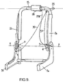
- the figure 1 represents a vehicle seat 1, including a front seat intended to equip a vehicle that has only two side doors.
- This seat 1 comprises a backrest 2 which is pivotally mounted on a seat 3 about a pivot axis, or folding, horizontal X, to adjust the inclination of the backrest in the use position also called comfort position.
- the angular adjustment of the raised position of use of the backrest is made according to a range of raised positions of use between a raised position back and a raised position before the backrest 2.
- This adjustment can be carried out by a user by means of a hinge 4 known per se, controlled by a first control member, for example a rotary handle, as in the embodiments presented here, or the like. Examples of such joints are given, for example, in the document FR-A-2,740,406 .
- the hinge 4 is adapted to allow a rotation of the backrest 2 relative to the seat 3, around the pivot axis X, along an angular stroke including a notched portion on which the user can block the backrest 2 relative at the seat 3 in a comfortable position, and a free portion on which the rotation of the backrest 2 relative to the seat 3 is unlocked.
- the seat 3 is carried by two parallel runners 6, only one of which is visible on the figure 1 , which are normally locked so as to immobilize the seat 1, but can be unlocked by means of a rudder bar 7 or other actuating member (such as that shown in FIGS. Figures 4 to 21 ), to allow a sliding of the entire seat 1 forwards or backwards in a longitudinal direction L.
- Each of the slides 6 usually comprises a fixed section 8 which is integral with the floor 9 of the vehicle and a movable profile 10 which slides relative to the fixed section 8 and which is integral with the seat 3 of the seat 1.
- the user actuates the handle 5, upwards, in the direction of the arrow f.
- the handle 5 controls the articulation 4 to disengage it.
- the user can then tilt the backrest 2 more or less backwards or forwards, between the raised back position and the raised front position of the backrest 2, according to an angular stroke corresponding to the notched part of the articulation 4
- the handle 5 releases the handle 5, which returns elastically to its initial position.
- the hinge 4 is then locked again and the tilting of the backrest 2 relative to the seat 3 is again blocked.
- the backrest 2 of the seat in tablet position by rotating it further forward in the direction of the arrow R, as shown in FIG. figure 3 .
- the backrest 2 extends substantially parallel to the seat 3, the rear face of the backrest being preferably sufficiently rigid to serve as a bearing surface and thus constitute a tablet.
- the first embodiment of the seat according to the invention is described below in relation to the Figures 4 to 8 .
- the tilting of the backrest 2 relative to the seat 3 is controlled by a mechanism comprising the hinge 4 located on one side of the seat 1 and a locking mechanism 11, located on the side of the seat 1 opposite to that on which is mounted the articulation 4.
- control member for activating the comfort adjustment function and the control member for activating the tilting function of the backrest 2 in an intermediate folded position coincide and correspond to the handle 5, while the control member for activating the tilting function of the backrest 2 in the tablet position is separated and distinct from the previous one and corresponds to a handle 28.
- the main metal frame of the seat 3 comprises two first side plates 3a, 3b interconnected by the front 12 and rear 13 crosspieces.
- the first side plates 3a, 3b rest on the slides 6.
- the rotation of the first side flanges 3a, 3b with respect to the second lateral flanges 2a, 2b is controlled by the articulation 4 and the locking mechanism 11.
- the articulation 4 and the locking mechanism 11 are respectively mounted between the first 3a, 3b and second 2a, 2b lateral flanges coaxially with respect to the horizontal pivot axis X.
- a cross member 15 interconnects the second side flanges 2a, 2b, and allows these two flanges to rotate simultaneously. Indeed, there is no connecting shaft between the hinge 4 and the locking mechanism 11.
- the locking mechanism 11 of this embodiment is illustrated in detail on the Figures 5, 6, 7, 8 corresponding to various positions of the backrest 2 relative to the seat 3.
- the figure 5 shows the locking mechanism 11 in the position of the backrest 2 shown in figure 1 (in its range of raised positions, in rear comfort position).
- the locking mechanism 11 comprises, on the one hand, a rotatable member 16 intended to be secured to the lateral flange 2a, for example, by crimping or welding, and on the other hand, a locking member 18 mounted to move on the flange 3b of the seat 3, around a pivot point 20.
- the rotary member 16 is provided with a first stop 17.
- the locking member 18 does not interfere with the first stop 17 of the rotary member 16.
- this first stop 17 is offset angularly with respect to a counter-stop 19 projecting on the locking member 18, and the latter comes into contact with the first stop 17, when the rotary member 16 has pivoted about the pivot axis X, as shown in FIG. figure 6 for example, then corresponding to an active position of the locking member 18.
- the locking mechanism 11 is disengaged and allows the free rotation of the rotary member 16 relative to the flange 3b of the seat 3 on a comfort adjustment range P C.
- a user can, on this range, adjust the comfort position of the backrest 2 through the hinge 4 on the other side of the seat 1.
- the comfort adjustment range P C extends between the rear raised position and the raised position before.
- the backrest 2 has overtaken the raised position before to come in intermediate position adapted to allow a user access to the rear seats, in particular to settle in the back seat or leave this seat.
- the user actuates the handle 5 of the hinge 4, in the direction of the arrow f ', downwards (see figure 1 ), so as to position it in an angular sector corresponding to an unlocked position of the hinge 4 and tilts the backrest 2 about the pivot axis X, in a swinging range P B forwards, in the direction of the arrow R, as shown in figure 2 , until reaching an intermediate folded position which exceeds the range of raised positions of use.
- the rotary member 16 further comprises a cam surface 22 adapted to actuate a lever 23 mounted to move on the first lateral flange 3b of the metal frame of the seat 3 around a pivot point 24.
- This lever 23 has at one of its ends a cam follower 25, and at its other end, a cable 26 connected to the control beam 7 of the slides 6.
- the lever 23 is in an active position in which the cam follower 25 is in contact with the cam surface 22 and causes the slides 6 to be unlocked thanks to the traction exerted by the cable 26 (typically a "BOWDEN" type cable ) on the rudder 7, the lever 23 pivoting about its hinge point 24 in the direction of the arrow f1.
- the cable 26 typically a "BOWDEN" type cable
- a second control member for example a handle 28, separate and separate from the handle 5, and arranged for example on the top of the backrest 2, that is to say at the level of the upper half of this file 2, as shown on the Figures 1 to 3 , or even more precisely on the upper part of the rear face of the backrest 2, as represented on the figure 4 .
- the handle 28 is connected via connecting members 29a and 29b, typically "Bowden” type cables, respectively connected to a transmission member 21 and to the hinge 4.
- the figure 7 represents the locking mechanism 11 in a position corresponding to the beginning of the rotational movement of the rotary member 16, from a raised position, to the tablet position. To reach this position, it is necessary to actuate the lever 28.
- the cable 29a then moves the transmission member 21 in the direction of the arrow f3.
- This transmission member 21 allows the locking member 18, which is in the retracted position, to no longer interfere with the rotary member 16.
- the first stop 17 escapes from the abutment 19, thanks to the pivoting of the blocking member 18 around its pivot point 20 so that the rotary member 16, which is integral with the backrest frame 2, can continue its rotational movement about the pivot axis X to to reach the fully folded position of the backrest 2.
- the figure 8 represents the blocking mechanism 11 in a position corresponding to the position of tablet of the file 2.
- the slides 6 are locked. Indeed, because of the pivoting of the rotary member 16, the cam surface 22 pivots in the direction of the arrow f2, releases the lever 23 and is placed in the retracted position in which the cam follower 25 no longer interferes with the cam surface 22.
- the lever 23 being elastically biased towards its rest position, the cable 26 expands allowing the slides 6 to be locked.
- the rotary member 16 is provided with a second stop 27 cooperating with the abutment 19 and a third stop 14 adapted to cooperate with a notch 30 formed on the locking member 18.
- the notch 30 is located upstream of the abutment 19, relative to the tilting movement of the backrest 2, the tablet position to the raised position.
- the backrest 2 when the backrest 2 is in tablet position, it is preferable that the latter does not fall back beyond a substantially horizontal position and that it is able to support, in this position of tablet , a downward force, for example when a large weight is placed on its rear face.
- the rotary member 16 has a fourth stop 31, reinforced relative to the first 17 and second 27 stops, which is intended to interfere with a pin 32, located in extension of the axis of rotation materialized by the pivot point 20.
- the user actuates the handle 28 which then pulls on the connecting member 29a, in the direction of the arrow f3.
- This latter actuates the transmission member 21 so as to allow the stop against 19 of the locking member 18 to no longer interfere with the third stop 14, thus making possible the angular movement of the rotary member 16 in a direction to bring the backrest 2 into its position of use, as represented in figures 1 and 5 .
- the articulation 4 re-locks in a manner consistent with the teaching of the document FR-A-2,740,406 in order to freeze the position of the file 2.
- the comfort adjustment control member and the control member for folding the backrest 2 into an intermediate position are distinct.
- the control member for folding the backrest 2 into an intermediate position is placed for example on the backrest side 2, in the upper half thereof, and is connected to the hinge 4 by a cable ( similarly to what is described in connection with the following embodiment).
- the seat 1 corresponding to this second embodiment, comprises a backrest 2 pivotally mounted on a seat 3 around a horizontal pivot axis X, and a hinge 4 controlled by a control member, for example a rotary handle 5 (see figure 1 ).
- a control member for example a rotary handle 5 (see figure 1 ).
- the seat 3 is carried by two rails 6, the unlocking can be effected by means of a rudder 7.
- the tilting of the backrest 2 relative to the seat 3 is controlled by a mechanism comprising a hinge 4 located on one side of the seat 1 and a locking mechanism 11, located on the side of the seat 1 opposite to that on which is mounted l articulation 4.
- the control member for activating the comfort adjustment function that is to say the handle 5
- the control member for activating the function of tilting the backrest 2 in the tablet position that is to say a joystick 28, are separate and separate.
- the hinge 4 and the locking mechanism 11 are respectively mounted between the first lateral flanges 3a, 3b, the seat 3 and the second lateral flanges 2a, 2b, of the backrest 2, coaxially with respect to the pivot axis X horizontal.
- a cross member 15 interconnects the second side flanges 2a, 2b and allows these two flanges to rotate simultaneously.
- the crosspiece 15 carries the lever 28, intended to be protruding at the top of the rear face of the backrest 2, and the lever 35 intended to protrude on the same side of the backrest 2 as the articulation 4 and the handle 5.
- the handle 28 is connected to the hinge 4 by a connecting member 29b (for example, a "Bowden” cable).
- the lever 35 is connected to the locking mechanism 11 by another connecting member 36 (for example, a "Bowden” cable) and to the articulation 4 by yet another connecting member 37 (for example, a "Bowden” cable ).
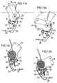
- the locking mechanism 11 of this embodiment is illustrated in detail on the Figures 10a, 10b , 11a, 11b, 12a and 12b corresponding to various positions of the backrest 2 relative to the seat 3.
- Figures 10a and 10b show the locking mechanism 11 in the position of the backrest 2 shown on the figure 1 (in its rear comfort position).
- the locking mechanism 11 comprises, on the one hand, a rotatable member 16 intended to be secured to the lateral flange 2b, for example by crimping or welding, and on the other hand, a locking member 18 mounted to move on the flange 3b of the seat 3, around a pivot point 20.
- the rotary member 16 is provided with a first stop 17.
- the locking member 18 does not interfere with the first stop 17 of the rotary member 16.
- this first stop 17 is offset angularly with respect to a stop 19 protruding from the locking member 18
- the stop 19 comes into contact with the first stop 17 only when the rotatable member 16 has pivoted about the pivot axis X, as shown in FIGS. Figures 11a and 11b , for example, which correspond to an active position of the locking member 18 and to the intermediate folded position of the backrest 2.
- the locking member 18 is in the retracted position, in which position it is resiliently biased by a spring 33.
- the rotary member 16 comprises a cam surface 22 adapted to actuate a lever 23.
- This lever 23 is pivotally mounted about an axis 24 located between a first end cooperating with the cam surface 22 and a second end connected to a cable 26 actuating the lifter 7.
- a spring 34 biases the lever 23 to an active position.
- the cam surface 22 is adapted to maintain the lever 23 in a passive position in which it does not stress the cable 26.
- the locking member 18 is biased resiliently by the spring 33 to a position in which it holds the lever 23 in its passive position.
- the locking mechanism 11 is disengaged and allows the free rotation of the rotary member 16 relative to the flange 3b of the seat 3 over the entire range of comfort adjustment P C , on which only the articulation 4 controls the position of the backrest 2 with respect to the seat 3.
- the Figures 11a and 11b represent the locking mechanism 11 in a configuration corresponding to the intermediate folded position allowing access to the rear seats.
- the user has, thanks to the lever 35 and the connecting members 36 and 37, on the one hand, unlocked on one side the articulation 4 and, on the other hand, requested the locking member 18 upwards, that is to say by imposing a force contrary to the action of the spring 33.
- the unlocking of the hinge 4 allows the user to tilt the folder 2 in the direction of the arrow R (see figure 2 ).
- Actuation of the locking member 18 releases it from the lever 23, allowing the latter to follow the cam surface 22.
- the cam surface 22 is adapted so that the lever 23, under the action of the spring 34, pivots around the hinge point 24 and pulls on the cable 26 which unlocks the slides 6.
- the locking member 18 is held in its active position corresponding to a pull of the cable 26, by the lever 23.
- the first stop 17 of the rotary member 16 comes into contact with the abutment 19 of the locking member 18, thus preventing the backrest 2 from pivoting towards its tablet position.
- the locking member 18 under the action of the spring 33, then returns to the position it occupied in the configuration corresponding to the Figures 10a and 10b to maintain the lever 23 in the passive position.
- the Figures 12a and 12b correspond to a position of the file 2 put in tablet.
- the user straightens the backrest 2 in the comfort position, as indicated in the previous paragraph, then actuates the handle 28 which is connected by the connecting member 29b to the articulation 4 to unlock the latter and toggles the backrest 2 in the direction of the arrow R (see figure 3 ) until a second stop 27 of the rotary member 16 comes into contact with the abutment 19 of the locking member 18.
- the lever 23 is blocked by the locking member 18 in its passive position in which the cable 26 is not pulled and therefore the slides 6 remain locked.
- the backrest 2 is held in its tablet position on the one hand by the action of the spring 34 which opposes a movement of the backrest 2 to a rectified position and, on the other hand, by the cooperation of the second stop 27 and against the stop 19 preventing the rotation of the backrest 2 towards the seat 3, beyond the tablet position.
- the comfort adjustment control member and the control member for folding the backrest 2 into an intermediate position are combined.
- it is for example a single handle 5, as for the first embodiment, which can be actuated in one direction, for comfort adjustment, and in another, to unlock the articulation 4 and allow a tilting of the backrest 2 for access to the rear seats.
- the third embodiment is described in more detail below in connection with the Figures 1 to 3 and 13 to 17 .
- the seat 1 corresponding to this third embodiment, comprises a backrest 2 pivotally mounted on a seat 3 around a horizontal pivot axis X, and a hinge 4 controlled by a control member, for example a rotary handle 5 (see figure 1 ).
- the seat 3 is carried by two rails 6, the unlocking can be effected by means of a rudder 7.
- the tilting of the backrest 2, relative to the seat 3, is controlled by a mechanism comprising a hinge 4 located on one side of the seat 1 and a locking mechanism 11 located on the side of the seat 1 opposite to that on which is mounted the articulation 4.
- control member for activating the comfort adjustment function and the control member for activating the tilting function of the backrest 2 in the tablet position are merged and correspond to the handle 5, but they are distinct from the control member for activating the tilting function of the backrest 2 in an intermediate folded position, corresponding to a lever 35.
- the articulation 4 and the locking mechanism 11 control the rotation of the first lateral flanges 3a, 3b of the seat 3 relative to the second lateral flanges 2a, 2b of the backrest 2.
- a cross member 15 interconnects the second side flanges 2a, 2b and allows these two flanges to rotate simultaneously.
- the crosspiece 15 carries the lever 35, intended to protrude on the same side of the backrest 2 as the articulation 4 and the handle 5.
- the lever 35 is connected to the locking mechanism 11 by a connecting member 36 (for example, a cable "Bowden”) and the hinge 4 by another connecting member 37 (for example, a cable "Bowden").
- the locking mechanism 11 of this embodiment is illustrated in detail on the figure 14 , as well as on Figures 15, 16 and 17 corresponding to various positions of the backrest 2 relative to the seat 3.
- This locking mechanism 11 comprises a locking member 18 and a lever 23.
- the locking member 18 and the lever 23 are both pivotally mounted on the second lateral flange 2b, situated on the other side of the seat 1 with respect to the articulation 4.
- the backrest 2 is articulated on the seat 3, around a horizontal pivot axis X.
- a torsion spring 34 resiliently recalls the backrest 2 to the intermediate folded position and the tablet position.
- the spring 34 has an outer end bearing on a stop 38 secured to the first flange 3b of the seat 3.
- the inner end of the spring 34 cooperates with a pivot 39 rendering rotationally integral the spring 34 and the backrest 2.
- the locking member 18 is fixed, by means of a screw 40 on a plate 41, itself held on the flange 2b by screws 42.
- the locking member 18 is able to pivot about a horizontal axis materialized by the screw 40.
- the locking member 18 is rotatable about the screw 40, between a retracted position in which it does not interact with the lever 23, and an active position, in which it causes the rotation of the lever 23 with the backrest 2, when the latter pivots around the pivot axis X, a comfort position to the intermediate folded position.
- the locking member 18 comprises a point of attachment 43 of the connecting member 36. It also comprises near this point of attachment 43 another attachment point 44 of a spring 33. The spring 33 recalls the locking member 18 to its retracted position.
- the locking member 18 comprises a hook 45 intended to cooperate with the lever 23.
- the lever 23 is rotatably mounted around the pivot 39 by means of a spacer 46.
- the lever 23 is held on the pivot 39 between the second lateral flange 2b and the plate 41.
- the first 3b and second 2b side flanges are held together by a screw 47 screwed into the pivot 39.
- the pivot 39 passes through the second lateral flange 2b, the spacer 46 and the lever 23.
- the lever 23 includes a hook 48 intended to cooperate with the hook 45 of the locking member 18.
- the lever 23 also comprises, near the hook 48, an attachment point 49 of the connecting member controlling the locking and 6.
- this connecting member is a cable 26 of the "Bowden" type.
- the lever 23 comprises a branch 50 extending substantially radially perpendicular to the pivot axis X.
- the lever 23 has an attachment point 51 for the spring 33.
- the spring 33 recalls the locking member 18 in the retracted position (shown in dashed lines on the figure 15 ).
- the locking mechanism 11 is disengaged and allows the free rotation of the second lateral flange 2b with respect to the first lateral flange 3b over the entire comfort adjustment range, on which only the articulation 4 controls the position of the backrest 2 relative to the seat 3.
- a user actuates the lever 35 to tilt the backrest 2 in the intermediate folded position, it unlocks on the one hand the articulation 4 and on the other hand pulls on the body link 36 which tilts the locking member 18 in the active position, against the action of the spring 33.
- the unlocking of the hinge 4 allows the user to tilt the folder 2 in the direction of the arrow R (see figure 2 ).
- the hook 45 of the locking member 18 then cooperates with the hook 48 of the lever 23.
- the lever 23 is rotated with the second side flange 2b.
- the user can release the lever 35, the hinge 4 being in a free running portion of rotation.
- the branch 50 bearing on the stop 38, prevents the backrest 2 from pivoting to its tablet position.
- the backrest 2 When the backrest 2 is in the intermediate folded position and the user releases the lever 35, the backrest 2 remains in the intermediate folded position, thanks to the action of the spring 34 which recalls the backrest 2 to the tablet position. In the intermediate folded position, the hooks 45 and 48 continue to cooperate together even if the lever 35 is released.
- the slides 6 being unlocked the user can advance the seat 1 so as to clear the space sufficient to allow access to the seats located behind the seat 1.
- the user raises the backrest 2 against the action of the spring 34.
- the lever 23 returns in a clockwise direction with the backrest 2, under the effect of return of the cable 26.
- the spring 33 tends to disengage the hooks 45 and 48 from one another.
- the locking member 18 can then go back to the retracted position.
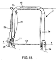
- the fourth embodiment is described in more detail below in connection with the Figures 1 to 3 , 18 and 19 .
- the seat 1 comprises a backrest 2 pivotally mounted on a seat 3 around a horizontal pivot axis X (see figure 1 ).
- the seat 3 is carried by two slides 6 whose unlocking can be effected by means of a rudder 7.
- the main metal armature of the seat 3 comprises two first lateral flanges 3a, 3b respectively connected to second side flanges 2a, 2b constituting the backrest 2.
- the first side flanges 3a, 3b rest on the slides 6.
- the tilting of the backrest 2 relative to the seat 3 is controlled by a mechanism comprising a hinge 4 and a locking mechanism 11 located on the same side of the seat 1.
- control member for activating the comfort adjustment function and the control member for activating the tilting function of the backrest 2 in the tablet position are merged and correspond to each other. to a handle 5. But they are separate from the control member, corresponding to a lever 35, for activating the tilting function of the backrest 2 in an intermediate folded position.
- the first 3a, 3b and second 2a, 2b side flanges of the seat 3 and the backrest 2 are rotatably assembled around a connecting bar 51 extending longitudinally parallel to the pivot axis X.
- a cross member 15 interconnects the second side flanges 2a, 2b.
- the crosspiece 15 carries the lever 35, intended to protrude on the same side of the backrest 2 as the articulation 4 and the handle 5.
- the lever 35 is connected to the locking mechanism 11 by a connecting member 36 (for example, a cable "Bowden").
- the locking mechanism 11 of this embodiment is illustrated in detail on the figure 19 .
- This locking mechanism 11 comprises a locking member 18 and a lever 23.
- the locking member 18 and the lever 23 are both pivotally mounted on the second lateral flange 2b.
- the locking member 18 is fixed, by means of a pivot 40, to a plate 41, itself held on the flange 2b by means of a screw 42.
- the locking member 18 is able to rotate on the pivot 40, around an axis substantially parallel to the pivot axis X, between a retracted position in which it does not interact with the lever 23, and an active position, in which it causes the rotation of the lever 23 with the backrest 2, when it pivots around the pivot axis X, a comfort position to the intermediate folded position.
- the locking member 18 is biased towards its retracted position, by a torsion spring 52 bearing on the one hand on a tab 53 formed by a folded portion of the plate 41, and on the other hand on a flat part. a part of the locking member 18 extending coaxially with the pivot 40 and fixed relative to the flange 2b.
- the locking member 18 has an attachment point 43 of the connecting member 36.
- the locking member 18 comprises a hook 45 intended to cooperate with the lever 23.
- the lever 23 is rotatably mounted around the connecting shaft 51 between a passive position in which it allows the locking of the slides and an active position in which it actuates a connecting member (not shown) which controls the unlocking of the slides 6.
- the lever 23 comprises a hook 48 intended to cooperate with the hook 45 of the locking member 18.
- the lever 23 also comprises, opposite the hook 48 relative to the connecting shaft 51, means of attachment of the connecting member controlling the locking and unlocking of the slides 6.
- a torsion spring 54 resiliently removes the lever 23 towards its passive position.
- the locking mechanism 11 is shown in disengaged configuration. It allows the free rotation of the second lateral flange 2b with respect to the first lateral flange 3b over the entire range of comfort adjustment and to the tablet position, for which only the articulation 4 controls the position of the backrest 2 by relation to the seat 3.
- the hook 45 of the locking member 18 then comes to face the hook 48 of the lever 23.
- the hinge 4 being unlocked, it suffices for the user to tilt the backrest 2 forward in the intermediate folded position, to access the rear seats of the vehicle.
- the locking member 18 is driven with the flange 2b.
- the two hooks 45 and 48 then cooperate together, which also drives the lever 23 in rotation about the pivot axis X, against the return force of the torsion spring 54.
- the lever 23 pulls on the connecting member controlling the unlocking of the slides 6.
- the rotation of the backrest 2 is limited by the coming of the lever 23 abuts on the flange 3b.
- the lever 23 When the user returns the backrest 2 to the rear, the lever 23 is returned to its passive position corresponding to the figure 19 .
- the lever 23 When the lever 23 is in the passive position, it no longer exerts force between the hooks 45 and 48.
- the locking member 18 can then return, thanks to the restoring force of the torsion spring 52, in the retracted position, if no more force is exerted on the connecting member 36.
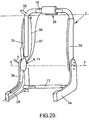
- the fifth embodiment is described below in connection with the Figures 1 to 3 and 20 to 33 .
- the seat 1 corresponding to this embodiment, comprises a backrest 2 pivotally mounted on a seat 3 about a horizontal pivot axis X (see figure 1 ).
- the seat 3 is carried by two rails 6, the unlocking can be effected by means of a rudder 7.
- the tilting of the backrest 2 relative to the seat 3 is controlled by a mechanism comprising a hinge 4 and a locking mechanism 11, both located on the same side of the seat 1.
- control member for activating the comfort adjustment function corresponding to a handle 5
- control member for activating the tilting function of the backrest 2 in the tablet position corresponding to the joystick 28, and the control member for activating the tilting function of the backrest 2 in an intermediate folded position, corresponding to the lever 35, are distinct from each other.
- the main metal frame of the seat 3 comprises two first lateral flanges 3a, 3b respectively connected to second side flanges 2a, 2b Components of the backrest 2.
- the first lateral flanges 3a, 3b rest on the slideways 6.
- the first two lateral flanges 3a, 3b are interconnected by a rear crossmember 13.
- the crosspiece 15 carries the lever 35, intended to protrude on the same side of the backrest 2 as the articulation 4 and the handle 5.
- the lever 35 is connected to the locking mechanism 11 by a connecting member 36 (for example, a cable “Bowden”).
- the crosspiece 15 also carries the handle 28, intended to be projecting on the rear face of the backrest 2.
- the handle 28 is connected to the locking mechanism 11 by a connecting member 37 (for example, a "Bowden" cable).
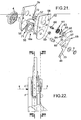
- the locking mechanism 11 is illustrated in detail on the figure 21 , as well as on Figures 22 to 33 corresponding to various positions of the backrest 2 relative to the seat 3.
- This locking mechanism 11 comprises locking means 18a and a lever 23.
- the locking means 18a comprise a toothed disc 55, a locking hook 56 and a cam 57.
- the locking means 18a are enclosed in a housing constituted by a part of the side flange 2b and a closure plate 58.
- the locking hook 56 pivots about an axis substantially parallel to the pivot axis X and materialized by a hook pivot 59.
- the cam 57 pivots about an axis substantially parallel to the pivot axis X and materialized by a cam pivot 60.
- the cam pivot 60 is resiliently biased by a torsion spring 61.
- the torsion spring 61 is prestressed between an inner end cooperating with a flat formed on the cam pivot 60 and an outer end abutting a tab 62 formed on the closure plate 58.
- the cam pivot 60 is actuated via a tablet control link 63 and a rear seat access control link 64.
- the tablet control link 63 and the link rod rear seat access control 64 are pressed against each other and held together on the cam pivot 60.
- the tablet control link 63 is rotatably connected to the cam pivot 60. It comprises on the one of its faces, that vis-à-vis the rear seat access control rod 64, two pins 65.
- the rear seat access control rod 64 comprises two cutouts 66 extending in an arc of a circle centered on the axis of rotation of the cam pivot 60.
- the rear seat access control rod 64 is positioned, relative to the tablet control link 63, so that the pins 65 engage in cuts 66.
- the rear seat access control rod 64 is free to rotate about the cam pivot 60. Thus, on the angular range corresponding to the arc of the cutouts 66, the tablet control link 63 may be actuated without causing, in its movement, the rear seat access control rod 64.
- the rear seat access control rod 64 also includes a boarding pin 69.
- This boarding pin 69 extends perpendicularly to the plate constituting the rear seat access control rod 64; ie parallel to the pivot axis
- the tablet control rod 63 is connected to the lever 28 by the connecting member 37.
- the rear seat access control rod 64 is connected to the lever 35 by the connecting member 36.
- the connecting rod rear seat access control 64 is connected to the connecting member 36 at a point of attachment 43.
- the toothed disk 55 is in the form of a ring with a notched internal surface intended to cooperate with the hinge 4, so as to make the hinge 4 and the toothed disk 55 integral in rotation.
- the toothed disk 55 also comprises a peripheral outer surface comprising two notched zones provided with teeth intended to cooperate with homologous teeth made on the locking hook 56. These two notching zones are respectively a comfort notch zone 70 and a zone notching tablet 71.
- the locking hook 56 has a sector intended to cooperate with the cam surface of the cam 57.
- the lever 23 consists of a sheet metal pressed to form a guide 67.
- the guide 67 forms, when the lever 23 is mounted on the closure plate 58, a tunnel extending in an arc around the axis X. One of the ends of this tunnel is flared to form a radial extension constituting a stop 68.
- the lever 23 is connected, at a point of attachment 49, to a connecting member 26 controlling the locking or unlocking the slides 6.
- the locking mechanism 11, as shown on the figure 22 once assembled, can be broken down into a control stage of the comfort setting and the setting in tablet, more particularly represented on the figure 23 , as well as a control stage of the access to the rear seats, more particularly represented on the figure 24 .
- the adjustment in the comfort position is illustrated on the Figures 25 to 27 .
- the cam 57 remains fixed and cooperates with the sector of the locking hook 56, so as to maintain it in engagement with the comfort notching zone 70 of the toothed disc 55.
- the toothed disc 55, as well as the entire locking mechanism 11, then rotate integrally around the pivot axis X with the flange 2b and thus the backrest 2.
- This rotational movement in the comfort adjustment range can be performed between a raised position before, corresponding to the figure 25 and a raised rear position, corresponding to the figure 27 passing through intermediate positions of the type represented on the figure 26 .
- the boarding pin 69 moves freely in the guide 67.
- the rotation of the backrest 2 in the adjustment range in the comfort position does not cause the lever 23 to move.
- the slides 6 therefore remain locked.
- the toothed disc 55 comprises a tab 73 which cooperates, in the rear raised position, with a stop 74 in the fixed position of the flange 3b, so as to limit the range of comfort adjustment.
- the user To rotate the backrest 2 from a comfort position to the intermediate folded position, the user must actuate the lever 35. Thus, traction is exerted on the connecting member 36. This traction rotates the control rod of access to the rear seats 64 around the cam pivot 60. After a dead stroke of the pins 65 in the cutouts 66, the rear seat access control rod 64 also drives the tablet control rod 63. Thus, the movement is transmitted to the cam pivot 60 and the cam 57.
- the cam 57 interacts with the sector 72 of the locking hook 56 so as to disengage it from the comfort-locking zone 70.
- the locking mechanism 11 and the backrest 2 are thus separated from the articulation 4.
- the user can then switch the folder 2 to the intermediate folded position.
- the boarding pin 69 has been moved.
- the trajectory of the boarding pawn 69, during the tilting of the backrest 2 towards the intermediate folded position, is outside the tunnel of the guide 67.
- the boarding pawn 69 then cooperates, in the intermediate folded position of the backrest 2, with the stop 68 ( figure 29 ).
- the boarding pin 69 thus causes in its rotation, that of the lever 23.
- the latter in its movement, pulls on the connecting member 26 thus enabling the slides 6 to be unlocked.
- the locking hook 56 rests on a non-toothed zone of the toothed disk 55 situated between the comforting notch zone 70 and the shelf engaging zone 71.
- the return to a comfort position is effected by tilting the backrest 2 towards the rear, without necessarily manipulating the lever 35, the reengagement of the locking hook 56 with the toothed disk 55, and thus the securing with the articulation 4, occurring only when no tooth of the locking hook 56 rests on the non-toothed area of the toothed disc 55.
- the tabling of the file 2 is illustrated by the Figures 31 to 33 .
- the user actuates the handle 28.
- the latter tends the connecting member 37.
- This tension causes the rotation of the control rod of tabletting 63, with the cam pivot 60 and the cam 57.
- the cuts 66 in this rotation of the tablet control rod 63, the rear seat access control rod 64 n is not trained.
- the cam 57 interacts with the sector 72 of the locking hook 56 so as to disengage the teeth of the latter from the comfort-locking zone 70 of the toothed disc 55.
- the user can then tilt the backrest 2 forward towards the position of putting in tablet.
- the rear seat access control rod 64 has not been driven with the tablet control rod 63, the boarding pawn 69 follows a course, during the rocking movement of the backrest 2 around the pivot axis X to the tablet position, in the guide 67.
- the handle 28 is released and the locking hook 56 cooperates again with the toothed disk 55, its teeth being engaged in those of the shelf-locking zone 71.
Landscapes
- Engineering & Computer Science (AREA)
- Aviation & Aerospace Engineering (AREA)
- Transportation (AREA)
- Mechanical Engineering (AREA)
- Seats For Vehicles (AREA)
- Chairs For Special Purposes, Such As Reclining Chairs (AREA)
Claims (19)
- Fahrzeugsitz (1) umfassend:- eine Sitzeinheit (3), dazu bestimmt mittels Gleitschienen (6) mit einem Fahrzeugboden (9) verbunden zu sein,- eine Rückenlehne (2), bezüglich der Sitzeinheit (3) um eine horizontale Schwenkachse (X) schwenkbar angeordnet, zwischen einer Ablagestellung, in der sich die Rückenlehne (2) im Wesentlichen parallel zur Sitzeinheit (3) erstreckt und einer Komfortstellung, in der sich die Rückenlehne (2) im Wesentlichen senkrecht zur Sitzeinheit (3) erstreckt und es einem Benutzer erlaubt sich auf den Sitz (1) zu setzen, wobei die Komfortstellung in einem Winkelbereich enthalten ist, sich erstreckend zwischen einer hinteren aufgestellten Stellung und einer vorderen aufgestellten Stellung der Rückenlehne erstreckt,- ein Steuerungsmechanismus für das Schwenkens der Rückenlehne (2) bezüglich der Sitzeinheit (3), geeignet die drei Funktionen zu gewährleisen, bestehend aus:■ Steuern (5) eines Gelenkes (4) die Rückenlehne (2) in einer Komfortstellung zu steuern,■ Steuern eines Umklappens der Rückenlehne (2), durch Rotation dieser um die Schwenkachse (X), hin zu der Ablagestellung, und■ Steuern eines Umklappens der Rückenlehne (2), durch Rotation dieser um die Schwenkachse (X), in einer heruntergeklappten Zwischenstellung zwischen einer der gesteuerten Komfortstellungen und der Ablagestellung,wobei der Steuerungsmechanismus das Gelenk (4) umfasst, welches zwischen einem entriegeltem Zustand, der eine freie Rotation der Rückenlehne (2) bezüglich der Sitzeinheit (3) um die Schwenkachse (X) erlaubt, und einem verriegeltem Zustand, indem die Rotation der Rückenlehne (2) bezüglich der Sitzeinheit (3) in einer Komfortstellung blockiert ist, betätigbar ist,
wobei der Sitz zudem zumindest zwei Steuerungseinrichtungen (5, 28 oder 35) aufweist, welche voneinander separiert sind und die auf den Steuerungsmechanismus wirken um jeweils zumindest eine der drei oben beschriebenen Funktionen zu aktivieren,
einen Griff (5), der ein Steuerelement des Gelenkes (4) zum Übergang vom verriegelten Zustand hin zum entriegelten Zustand des Gelenkes bildet,
wobei der Sitz dadurch gekennzeichnet ist, dass der Griff (5) um die Schwenkachse (X) drehbar ist. - Sitz gemäß Anspruch 1, einen Blockiermechanismus (11) umfassend, welcher umfasst:- eine Rotationeinrichtung (16), festgesetzt an einem Element des Sitzes, ausgewählt aus der Rückenlehne (2) und der Sitzeinheit (3), und- eine Blockiereinrichtung (18), von einer Übertragungseinrichtung (21) betätigt und beweglich an einem zweiten Element des Sitzes, ausgewählt aus der Rückenlehne (2) und der Sitzeinheit (3) und verschieden zu demjenigen, an dem die Rotationseinrichtung (16) festgesetzt ist, wobei die Blockiereinrichtung (18) versetzbar ist zwischen einer aktiven Stellung einerseits, in der sie in Kontakt mit einem ersten Anschlag (17) der Rotationsreinrichtung (16) kommt, wenn die Rückenlehne (2) in einer aufgestellten Zwischenstellung ist, dabei ein Schwenken der Rückenlehne (2) hin zu der Ablagestellung verhindernd, und einer eingezogenen Stellung andererseits, in der sie nicht mehr mit dem ersten Anschlag (17) wechselwirkt, wobei die Blockiereinrichtung (18) zu ihrer aktiven Stellung hin elastisch beaufschlagt ist.
- Sitz gemäß Anspruch 1, einen Blockiermechanismus (11) umfassend, welcher umfasst:- eine Rotationseinrichtung (16), festgesetzt an einem Element des Sitzes, ausgewählt aus der Rückenlehne (2) und der Sitzeinheit (3), und- eine Blockiereinrichtung (18), beweglich an einem zweiten Element des Sitzes, ausgewählt aus der Rückenlehne (2) und der Sitzeinheit (3) und verschieden zu demjenigen, an dem die Rotationseinrichtung (16) festgesetzt ist, wobei die Blockiereinrichtung (18) versetzbar ist zwischen einer aktiven Stellung einerseits, in der sie in Kontakt mit einem ersten Anschlag (17) der Rotationsreinrichtung (16) kommt, wenn die Rückenlehne (2) in einer aufgestellten Zwischenstellung ist, dabei ein Schwenken der Rückenlehne (2) hin zu der Ablagestellung verhindernd, und einer eingezogenen Stellung andererseits, in der sie nicht mehr mit dem ersten Anschlag (17) wechselwirkt, wobei die Blockiereinrichtung (18) zu ihrer aktiven Stellung hin elastisch beaufschlagt ist.
- Sitz gemäß einem der Ansprüche 2 oder 3, wobei die Blockiereinrichtung (18) so ausgebildet ist, dass sie mit der Rotationseinrichtung (16) in Eingriff kommt, die Rückenlehne (2) bezüglich der Sitzeinheit (3) festsetzend, wenn die die Rückenlehne in ihrer Ablagestellung ist.
- Sitz gemäß einem der Ansprüche 2 bis 4, wobei die Rotationseinrichtung (16) eine Nockenfläche (22) aufweist, dazu ausgelegt einen Hebel (23) zu betätigen, welcher dazu ausgelegt ist, die Gleitschienen (6) zur verriegeln oder zu entriegeln und welcher an der Rückenlehne (2) beweglich angebracht ist, zwischen einer aktiven Stellung, in der der Hebel (23) eine Entriegelung der Gleitschienen (6) bewirkt, und einer passiven Stellung, in der der Hebel (23) die Verriegelung der Gleitschienen (6) erlaubt.
- Sitz gemäß Anspruch 5, wobei der Hebel (23) elastisch zu seiner passiven Stellung hin beaufschlagt ist und die Nockenfläche (22) so ausgelegt ist, dass sie den Hebel (23) in seine aktive Stellung versetzt, wenn die Rückenlehne (2) in ihrer aufgestellten Zwischenstellung ist.
- Sitz gemäß Anspruch 5, wobei der Hebel (23) elastisch zu seiner aktiven Stellung hin beaufschlagt ist und die Nockenfläche (22) so ausgelegt ist, dass sieden Hebel (23) in seine passive Stellung versetzt, wenn die Rückenlehne (2) in einer Stellung der Komforteinstellung oder in ihrer Ablagestellung ist.
- Sitz gemäß einem der Ansprüche 6 oder 7, wobei der Hebel (23) dazu geeignet ist, die Blockiereinrichtung (18) in ihrer aktiven Position zu halten, wenn die Rückenlehne (2) in ihrer aufgestellten Zwischenstellung ist.
- Sitz gemäß Anspruch 1, umfassend einen Blockiermechanismus (11), der in seinem Schwenken um die Schwenkachse (X) an der Rückenlehne (2) festgesetzt ist.
- Sitz gemäß Anspruch 9, umfassend eine Blockiereinrichtung (18) und einen Hebel (23), beide schwenkbar and der Rückenlehne (2) angebracht, wobei die Blockiereinrichtung mittels der Steuerungseinrichtung (35) gesteuert wird, welche das Umklappen der Rückenlehne (2) in aufgestellter Zwischenstellung aktiviert, zwischen einer eingezogenen Stellung in der sie nicht mit dem Hebel (23) interagiert, und einer aktiven Stellung, in der sie die Drehung des Hebels mit der Rückenlehne veranlasst, wenn diese um die Schwenkachse (X) von einer Komfortstellung in die aufgestellte Zwischenstellung schwenkt.
- Sitz gemäß Anspruch 10, wobei der Hebel (23), wenn er von der Blockiereinrichtung (18) beim Schwenken der Rückenlehne (2) von einer Komfortstellung in die aufgestellte Zwischenstellung veranlasst wird, die Entriegelung der Gleitschienen (6) steuert.
- Sitz gemäß einem der Ansprüche 10 oder 11, wobei der Hebel (23) die Drehung der Rückenlehne (2) in aufgeklappter Zwischenstellung blockiert, wenn sie zu der Ablagestellung hin schwenkt, in Anlage kommend mit einem an der Sitzeinheit festgesetzten Element (38).
- Sitz gemäß einem der Ansprüche 10 bis 12, wobei die Blockiereinrichtung (18), mittels erster elastischer Mittel (52) in einer eingezogenen Stellung zurückgehalten ist, in welcher sie nicht mit dem Hebel (23) interagiert und der Hebel (23) mittels von den ersten elastischen Mitteln (52) zweiter unabhängiger elastischer Mittel (54) in einer passiven Stellung zurückgehalten wird, in der er nicht mit der Blockiereinrichtung (18) interagiert und die Verriegelung der Gleitschienen (6) erlaubt.
- Sitz gemäß Anspruch 9, wobei der Blockiermechanismus (11) einen Hebel (23) umfasst, schwenkbar an der Rückenlehne (2) angebracht und so ausgelegt, dass er die Verriegelung und die Entriegelung der Gleitschienen (6) steuert.
- Sitz gemäß Anspruch 14, wobei der Hebel (23) Führungsmittel (64, 67, 69) aufweist, dazu ausgelegt, dass der Hebel (23) hin zu seiner aktiven Stellung beaufschlagt ist, in der er die Entriegelung der Gleitschienen (6) bewirkt, bei der Drehung der Rückenlehne (2) aus einer Komfortstellung zu der aufgestellten Zwischenstellung, und um die Entriegelung der Gleitschienen (6) zu verhindern, wenn die Rückenlehne (2) in Ablagestellung ist.
- Sitz gemäß einem der vorangehenden Ansprüche, wobei die Steuerungseinrichtung (28), welche das Umklappen der Rückenlehne (2) hin zu der Ablagestellung aktiviert und die Steuerungseinrichtung (35), welche das Umklappen der Rückenlehne (2) hin zu der aufgestellten Zwischenstellung hin aktiviert, voneinander getrennt sind.
- Sitz gemäß einem der vorangehenden Ansprüche, wobei die Steuerungseinrichtung (35), welche das Umklappen der Rückenlehne (2) hin zu der aufgestellten Zwischenstellung hin aktiviert, an einer Stelle, ausgewählt aus dem Gelenk (4) dem oberen Abschnitt der Rückenlehne (2), angebracht ist.
- Sitz gemäß einem der vorangehenden Ansprüche, wobei eine der Steuerungseinrichtungen (28, 35) dazu geeignet ist, dass sie den Blockiermechanismus (11) betätigt, welcher an der anderen Seite des Sitze (1) bezüglich des Gelenkes (4) befindlich ist.
- Sitz gemäß einem der vorangehenden Ansprüche, wobei die Steuerungseinrichtung (28), welche das Umklappen der Rückenlehne (2) hin zu der Ablagestellung aktiviert, und die Steuerungseinrichtung (5), welche das Gelenk kontrolliert zusammengeführt sind.
Priority Applications (1)
| Application Number | Priority Date | Filing Date | Title |
|---|---|---|---|
| DE60212779T DE60212779T3 (de) | 2001-10-15 | 2002-10-11 | Fahrzeugsitz mit vorklappbarer Rückenlehne |
Applications Claiming Priority (4)
| Application Number | Priority Date | Filing Date | Title |
|---|---|---|---|
| FR0113258 | 2001-10-15 | ||
| FR0113258A FR2830803B1 (fr) | 2001-10-15 | 2001-10-15 | Siege de vehicule comportant un dossier rabattable vers l'avant |
| FR0204203A FR2830804B1 (fr) | 2001-10-15 | 2002-04-04 | Siege de vehicule comportant un dossier rabattable vers l'avant |
| FR0204203 | 2002-04-04 |
Publications (3)
| Publication Number | Publication Date |
|---|---|
| EP1302361A1 EP1302361A1 (de) | 2003-04-16 |
| EP1302361B1 EP1302361B1 (de) | 2006-06-28 |
| EP1302361B2 true EP1302361B2 (de) | 2013-05-01 |
Family
ID=26213218
Family Applications (1)
| Application Number | Title | Priority Date | Filing Date |
|---|---|---|---|
| EP02292509.3A Expired - Lifetime EP1302361B2 (de) | 2001-10-15 | 2002-10-11 | Fahrzeugsitz mit vorklappbarer Rückenlehne |
Country Status (5)
| Country | Link |
|---|---|
| US (1) | US7152923B2 (de) |
| EP (1) | EP1302361B2 (de) |
| JP (1) | JP3723797B2 (de) |
| DE (1) | DE60212779T3 (de) |
| FR (1) | FR2830804B1 (de) |
Families Citing this family (79)
| Publication number | Priority date | Publication date | Assignee | Title |
|---|---|---|---|---|
| FR2820696B1 (fr) * | 2001-02-15 | 2003-08-08 | Faurecia Sieges Automobile | Siege de vehicule dote d'un dossier rabattable |
| DE10146300A1 (de) * | 2001-09-19 | 2003-04-03 | Hammerstein Gmbh C Rob | Gelenkbeschlag für einen Kraftfahrzeugsitz mit vorkippbarer Rückenlehne |
| US7959230B2 (en) * | 2003-04-11 | 2011-06-14 | Johnson Controls Technology Company | Seating system for a vehicle |
| DE20310578U1 (de) * | 2003-07-04 | 2004-08-12 | Brose Fahrzeugteile Gmbh & Co. Kg, Coburg | Kraftfahrzeugsitz |
| DE102004002144B4 (de) * | 2004-01-15 | 2010-10-21 | Faurecia Autositze Gmbh | Fahrzeugsitz |
| US7077463B2 (en) * | 2004-04-06 | 2006-07-18 | Lear Corporation | Rear fold down cargo seat with tilt down cushion |
| JP2006006720A (ja) * | 2004-06-28 | 2006-01-12 | Aisin Seiki Co Ltd | 車両用シート格納装置 |
| DE102004045988B3 (de) * | 2004-09-22 | 2005-12-01 | Faurecia Autositze Gmbh & Co. Kg | Anzeige zur Signalisierung der Nichtverriegelung einer klappbaren Rückenlehne eines Kraftfahrzeugsitzes |
| DE102005009182A1 (de) * | 2005-03-01 | 2006-09-07 | Daimlerchrysler Ag | Kraftfahrzeug |
| US8152242B2 (en) * | 2005-04-04 | 2012-04-10 | Lear Corporation | Selective remote head restraint actuation |
| PL1926627T3 (pl) * | 2005-09-09 | 2011-09-30 | Johnson Controls Gmbh | Fotel samochodowy |
| DE102006002823B4 (de) * | 2006-01-19 | 2014-09-11 | Johnson Controls Gmbh | Fahrzeugsitz mit Höhenverstellbereich und Absenkposition |
| US7556315B2 (en) * | 2006-03-31 | 2009-07-07 | Lear Corporation | Latch actuator system |
| KR101398333B1 (ko) * | 2006-08-03 | 2014-05-22 | 존슨 컨트롤스 테크놀러지 컴퍼니 | 리클라이너 메커니즘 |
| US20080141798A1 (en) * | 2006-10-20 | 2008-06-19 | Lear Corporation | Stored energy trigger design |
| KR100778590B1 (ko) * | 2006-11-07 | 2007-11-22 | 현대자동차주식회사 | 자동차용 리어시트의 리클라이너 조절구조 |
| US20080111415A1 (en) * | 2006-11-14 | 2008-05-15 | Lear Corporation | Smartfold actuator for mechanism |
| DE102007002366B3 (de) * | 2007-01-13 | 2008-07-17 | Keiper Gmbh & Co.Kg | Beschlagsystem für einen Fahrzeugsitz |
| JP5225610B2 (ja) * | 2007-05-17 | 2013-07-03 | トヨタ紡織株式会社 | 車両用シート |
| US8476864B2 (en) * | 2007-06-13 | 2013-07-02 | Lear Corporation | Battery monitoring system |
| US8118367B2 (en) * | 2007-09-26 | 2012-02-21 | Lear Corporation | Multi-load floor smartfold hybrid |
| DE102007051180B4 (de) * | 2007-10-25 | 2009-11-12 | Lear Corporation, Southfield | Rücksitzlehnen-Verriegelung |
| DE102008036630A1 (de) * | 2007-10-26 | 2009-04-30 | C. Rob. Hammerstein Gmbh & Co. Kg | Vorklappbarer Kraftfahrzeugsitz mit einem Gelenkbeschlag |
| EP2209667A4 (de) * | 2007-11-12 | 2011-07-27 | Johnson Controls Tech Co | Sitzzurückklappmechanismus mit flachfaltfunktion |
| DE102008008935B3 (de) * | 2008-02-08 | 2009-09-03 | Keiper Gmbh & Co. Kg | Beschlag für einen Fahrzeugsitz |
| JP5125617B2 (ja) | 2008-03-03 | 2013-01-23 | トヨタ紡織株式会社 | 乗物用シート |
| US7931337B2 (en) * | 2008-03-20 | 2011-04-26 | Gm Global Technology Operations, Llc | Recliner release actuation through active materials |
| JP5207791B2 (ja) * | 2008-03-24 | 2013-06-12 | テイ・エス テック株式会社 | 車両用格納シート |
| JP5315757B2 (ja) * | 2008-04-08 | 2013-10-16 | トヨタ紡織株式会社 | 車両用シートの連結装置 |
| US7543890B1 (en) * | 2008-05-29 | 2009-06-09 | Tachi-S Co., Ltd. | Structure of fold-down automotive seat |
| EP2321146B9 (de) * | 2008-08-07 | 2018-05-02 | Magna Seating Inc. | Versenkbarer sitz mit kipp-gleit-mechanismus |
| WO2010033501A1 (en) | 2008-09-18 | 2010-03-25 | Johnson Controls Technology Company | Weldable attachment mechanisms |
| CN102171066A (zh) * | 2008-10-28 | 2011-08-31 | 李尔公司 | 座椅闭锁装置 |
| JP5396880B2 (ja) * | 2009-01-23 | 2014-01-22 | アイシン精機株式会社 | シート装置 |
| US8123298B2 (en) * | 2009-09-10 | 2012-02-28 | Friend Success, Inc. | Hinge assembly for boat seat |
| BR112012012237B1 (pt) * | 2009-11-26 | 2019-06-11 | Magna Seating Inc. | Conjunto de assento |
| FR2960193A1 (fr) * | 2010-05-21 | 2011-11-25 | Peugeot Citroen Automobiles Sa | Dispositif de controle de configuration pour un siege de vehicule, actionnable par l'avant et l'arriere de ce siege |
| KR101394083B1 (ko) * | 2010-06-24 | 2014-05-13 | 존슨 컨트롤스 테크놀러지 컴퍼니 | 전자기계식 푸시 버튼 차량 시트 작동 기구 |
| EP2428393B1 (de) | 2010-09-10 | 2019-11-13 | Faurecia Automotive Seating, Inc. | Easy-Entry-Rückenlehnenlösesystem für Fahrzeugsitz |
| FR2975052B1 (fr) * | 2011-05-11 | 2014-02-07 | Faurecia Sieges Automobile | Ensemble d'articulation pour siege de vehicule et siege de vehicule comprenant l'ensemble d'articulation |
| KR101241692B1 (ko) * | 2011-05-11 | 2013-03-11 | 주식회사다스 | 자동차 시트의 폴딩 리클라이닝 장치 |
| DE102011105360A1 (de) * | 2011-06-21 | 2012-12-27 | Keiper Gmbh & Co. Kg | Fahrzeugsitz, insbesondere Kraftfahrzeugsitz |
| DE102011052059B4 (de) * | 2011-07-22 | 2021-07-22 | Adient Luxembourg Holding S.À R.L. | Sitzbeschlag für einen Kraftfahrzeugsitz |
| JP5798876B2 (ja) * | 2011-10-12 | 2015-10-21 | シロキ工業株式会社 | 車両用シート装置 |
| FR2988656B1 (fr) * | 2012-03-29 | 2017-03-10 | Faurecia Sieges Automobile | Ensemble d'articulation pour siege de vehicule |
| DE102012011507A1 (de) * | 2012-06-09 | 2013-12-12 | GM Global Technology Operations LLC (n. d. Gesetzen des Staates Delaware) | Fahrzeugsitz, Fahrzeug und Verfahren hierzu |
| US8899679B2 (en) * | 2012-09-24 | 2014-12-02 | Lear Corporation | Seat assembly having a fold assist mechanism |
| US9102246B2 (en) * | 2013-01-07 | 2015-08-11 | Leggett & Platt Canada Co. | Cable synchronizer system |
| DE102013200292B4 (de) | 2013-01-11 | 2021-07-29 | Lear Corp. | Sitzanordnung und Verriegelungsmechanismus |
| US9403453B2 (en) * | 2013-08-27 | 2016-08-02 | Lear Corporation | Backrest stopper mechanism for an easy entry seat assembly |
| US9776532B2 (en) | 2013-09-20 | 2017-10-03 | Lear Corporation | Easy entry seat track adjuster |
| DE102014217754B4 (de) | 2013-09-20 | 2019-05-09 | Lear Corporation | Easy-Entry Sitzeinstellvorrichtung und Schienenanordnung |
| US10214119B2 (en) | 2013-09-20 | 2019-02-26 | Lear Corporation | Track adjuster |
| DE102014207606B4 (de) * | 2013-12-02 | 2024-09-05 | Keiper Seating Mechanisms Co., Ltd. | Vorschwenkmechanismus für einen Fahrzeugsitz und Fahrzeugsitz |
| KR101500211B1 (ko) * | 2013-12-03 | 2015-03-06 | 현대자동차주식회사 | 워크인 메모리 기능을 가지는 차량용 시트레일 장치 |
| US9403447B2 (en) * | 2014-05-15 | 2016-08-02 | Fca Us Llc | Vehicle seat including an interlock assembly |
| DE102014220474B4 (de) * | 2014-07-03 | 2023-03-30 | Adient Us Llc | Lehnenversteller für einen Sitz und Fahrzeugsitz |
| FR3024407B1 (fr) * | 2014-07-29 | 2018-11-16 | Faurecia Sieges D'automobile | Ensemble d'articulation et siege de vehicule automobile comportant un tel ensemble |
| US9586503B1 (en) * | 2015-08-28 | 2017-03-07 | Faurecia Automotive Seating Llc | Vehicle seat and torsion bar |
| DE102015115035A1 (de) * | 2015-09-08 | 2017-03-09 | Brose Fahrzeugteile Gmbh & Co. Kommanditgesellschaft, Bamberg | Verriegelungssystem für eine Sitzanordnung eines Kraftfahrzeugs |
| US10065536B2 (en) * | 2015-09-24 | 2018-09-04 | Fca Us Llc | Reclining seat for a vehicle |
| JP6609179B2 (ja) * | 2015-12-24 | 2019-11-20 | デルタ工業株式会社 | 自動車用シート |
| DE102016209007B4 (de) * | 2016-01-28 | 2021-09-16 | Adient Luxembourg Holding S.À R.L. | Fahrzeugsitz mit einem Easy-Entry-Modul |
| WO2017188900A1 (en) * | 2016-04-27 | 2017-11-02 | Assan Hanil Otomotiv Sanayi Ve Ticaret Anonim Sirketi | Adjustable backrest mechanism for car seats |
| US9868369B1 (en) | 2016-07-15 | 2018-01-16 | Ford Global Technologies, Llc | Tip and slide system for a vehicle seat |
| US10252644B2 (en) | 2016-09-06 | 2019-04-09 | Ford Global Technologies, Llc | Tip and slide system for a vehicle seat |
| US10220744B2 (en) * | 2016-11-09 | 2019-03-05 | Lear Corporation | Front seat backrest release system |
| US10239426B2 (en) * | 2017-01-05 | 2019-03-26 | Ford Global Technologies Llc | Performance seat assembly with improved entry system and modular head restraint assembly |
| US10232745B2 (en) * | 2017-02-27 | 2019-03-19 | Faurecia Automotive Seating, Llc | Actuating module for a vehicle seat |
| JP6867841B2 (ja) * | 2017-03-28 | 2021-05-12 | シロキ工業株式会社 | シートリクライニング装置 |
| US10308146B1 (en) * | 2018-01-25 | 2019-06-04 | Ford Global Technologies, Llc | Track release mechanism for a seating assembly |
| US10442320B2 (en) * | 2018-01-25 | 2019-10-15 | Ford Global Technologies, Llc | Four-way pitching mechanism for a seating assembly |
| US10899250B2 (en) | 2019-01-11 | 2021-01-26 | Ford Global Technologies, Llc | Seating assembly |
| US11685295B2 (en) * | 2020-06-25 | 2023-06-27 | Lear Corporation | Seat adjustment lever and mechanism |
| CN115429560B (zh) * | 2021-06-04 | 2025-07-25 | 上海酷哲动力系统有限公司 | 状态调节装置及轮椅 |
| RU210649U1 (ru) * | 2021-12-07 | 2022-04-25 | Игорь Владимирович Митюков | Опора кресла складного |
| CN116923208B (zh) * | 2022-04-01 | 2026-01-16 | 威马智慧出行科技(上海)股份有限公司 | 一种座椅靠背的快速调节装置及座椅靠背 |
| CN115195539B (zh) * | 2022-07-28 | 2023-06-30 | 东风柳州汽车有限公司 | 一种地锁解锁结构、汽车座椅组件以及汽车 |
| KR102730028B1 (ko) * | 2022-08-12 | 2024-11-15 | 현대트랜시스 주식회사 | 비상 탈출용 전동식 시트백 폴딩 장치 |
Citations (7)
| Publication number | Priority date | Publication date | Assignee | Title |
|---|---|---|---|---|
| US4615551A (en) † | 1983-06-28 | 1986-10-07 | Toyota Jidosha Kabushiki Kaisha | Apparatus for positioning the backrest of a vehicle seat |
| DE19510618A1 (de) † | 1994-05-19 | 1995-11-23 | Hammerstein Gmbh C Rob | Kraftfahrzeugsitz, der im vorgeklappten Zustand der Rückenlehne längsverschiebbar ist |
| US5779313A (en) † | 1995-10-27 | 1998-07-14 | Bertrand Faure Equipements Sa | Articulation for a vehicle seat |
| DE19715764A1 (de) † | 1997-04-16 | 1998-10-22 | Keiper Gmbh & Co | Neigungseinstellbeschlag mit Freischwenkeinrichtung für Rückenlehnen von Sitzen, insbesondere Kraftfahrzeugsitzen |
| DE69700609T2 (de) † | 1996-03-15 | 2000-05-31 | Cesa Compagnie Europeenne De Sieges Pour Automobiles, Levallois-Perret | Einstellbare Rücklehne für Fahrzeugsitz |
| FR2799420A1 (fr) † | 1999-10-08 | 2001-04-13 | Faure Bertrand Equipements Sa | Siege de vehicule |
| EP1318926A2 (de) † | 2000-09-21 | 2003-06-18 | Brose Fahrzeugteile GmbH & Co. KG, Coburg | Vorrichtung zur verstellung der lehnenneigung |
Family Cites Families (8)
| Publication number | Priority date | Publication date | Assignee | Title |
|---|---|---|---|---|
| FR2288645A1 (fr) * | 1974-02-20 | 1976-05-21 | Peugeot & Renault | Siege a dossier rabattable pour vehicule |
| JPS58199233A (ja) * | 1982-05-12 | 1983-11-19 | Mitsubishi Motors Corp | 自動車用ベンチ型シ−ト |
| US5588707A (en) * | 1995-11-14 | 1996-12-31 | General Motors Corporation | Folding seat |
| JP3630507B2 (ja) | 1996-08-20 | 2005-03-16 | シロキ工業株式会社 | シート |
| DE19644087B4 (de) * | 1996-10-31 | 2008-10-16 | C. Rob. Hammerstein Gmbh & Co. Kg | Lehnenbeschlag für einen Kraftfahrzeugsitz |
| WO1998054024A1 (en) | 1997-05-27 | 1998-12-03 | Bertrand Faure Components Ltd. | Slide/fold/ez entry seat mechanism |
| FR2803803B1 (fr) | 2000-01-14 | 2002-03-01 | Peugeot Citroen Automobiles Sa | Siege pliant a deverrouillage automatique pour vehicule automobile |
| US6554362B1 (en) * | 2001-04-03 | 2003-04-29 | Fisher Dynamics Corporation | Manual fold-flat seat hinge assembly |
-
2002
- 2002-04-04 FR FR0204203A patent/FR2830804B1/fr not_active Expired - Fee Related
- 2002-10-11 DE DE60212779T patent/DE60212779T3/de not_active Expired - Lifetime
- 2002-10-11 EP EP02292509.3A patent/EP1302361B2/de not_active Expired - Lifetime
- 2002-10-15 US US10/270,804 patent/US7152923B2/en not_active Expired - Lifetime
- 2002-10-15 JP JP2002300964A patent/JP3723797B2/ja not_active Expired - Lifetime
Patent Citations (8)
| Publication number | Priority date | Publication date | Assignee | Title |
|---|---|---|---|---|
| US4615551A (en) † | 1983-06-28 | 1986-10-07 | Toyota Jidosha Kabushiki Kaisha | Apparatus for positioning the backrest of a vehicle seat |
| DE19510618A1 (de) † | 1994-05-19 | 1995-11-23 | Hammerstein Gmbh C Rob | Kraftfahrzeugsitz, der im vorgeklappten Zustand der Rückenlehne längsverschiebbar ist |
| US5779313A (en) † | 1995-10-27 | 1998-07-14 | Bertrand Faure Equipements Sa | Articulation for a vehicle seat |
| DE69700609T2 (de) † | 1996-03-15 | 2000-05-31 | Cesa Compagnie Europeenne De Sieges Pour Automobiles, Levallois-Perret | Einstellbare Rücklehne für Fahrzeugsitz |
| DE19715764A1 (de) † | 1997-04-16 | 1998-10-22 | Keiper Gmbh & Co | Neigungseinstellbeschlag mit Freischwenkeinrichtung für Rückenlehnen von Sitzen, insbesondere Kraftfahrzeugsitzen |
| FR2799420A1 (fr) † | 1999-10-08 | 2001-04-13 | Faure Bertrand Equipements Sa | Siege de vehicule |
| EP1318926A2 (de) † | 2000-09-21 | 2003-06-18 | Brose Fahrzeugteile GmbH & Co. KG, Coburg | Vorrichtung zur verstellung der lehnenneigung |
| EP1318926B1 (de) † | 2000-09-21 | 2005-05-04 | Brose Fahrzeugteile GmbH & Co. KG, Coburg | Vorrichtung zur verstellung der lehnenneigung |
Also Published As
| Publication number | Publication date |
|---|---|
| FR2830804A1 (fr) | 2003-04-18 |
| DE60212779T3 (de) | 2013-07-18 |
| US20030080601A1 (en) | 2003-05-01 |
| EP1302361B1 (de) | 2006-06-28 |
| JP2003159140A (ja) | 2003-06-03 |
| JP3723797B2 (ja) | 2005-12-07 |
| US7152923B2 (en) | 2006-12-26 |
| DE60212779T2 (de) | 2007-06-28 |
| EP1302361A1 (de) | 2003-04-16 |
| DE60212779D1 (de) | 2006-08-10 |
| FR2830804B1 (fr) | 2004-01-16 |
Similar Documents
| Publication | Publication Date | Title |
|---|---|---|
| EP1302361B2 (de) | Fahrzeugsitz mit vorklappbarer Rückenlehne | |
| EP0723889B1 (de) | Fahrzeugsitzgleitschiene | |
| EP0381559B1 (de) | Neig- und klappbare Sitzlehne | |
| FR2766138A1 (fr) | Mecanisme d'articulation pour siege de vehicule, et siege de vehicule equipe d'un tel mecanisme | |
| FR2795688A1 (fr) | Siege de vehicule equipe d'un mecanisme d'articulation | |
| EP0913293A1 (de) | Gelenkmechanismus für Kraftfahrzeugsitz und mit solchem Gelenkbeschlag ausgerüsteter Kraftfahrzeugsitz | |
| CA2511897A1 (fr) | Mecanisme d'articulation pour siege de vehicule et siege comportant un tel mecanisme | |
| FR2766139A1 (fr) | Dispositif d'articulation pour siege de vehicule, et siege de vehicule comportant un tel dispositif | |
| FR2820696A1 (fr) | Siege de vehicule dote d'un dossier rabattable | |
| EP1067013A1 (de) | Vorrichtung zum Verstellen einer Sitzrückenlehne mit Doppelgelenk und einer einzelnen Betätigung | |
| FR2929179A1 (fr) | Siege de vehicule automobile et vehicule muni d'un tel siege. | |
| FR3083174A1 (fr) | Siege de vehicule automobile | |
| EP1518744B1 (de) | Rückenlehnegelenkbeschlag mit zeitlich abgestufter Winkelverstellung | |
| EP0800952A1 (de) | Kraftfahrzeugsitz, nach vorn bewegbar, um zu einem Hinterraum Zugang zu haben | |
| FR2845044A1 (fr) | Siege de vehicule automobile avec une articulation de dossier | |
| FR2527060A1 (fr) | Ensemble pour siege reglable a deux mecanismes de commande independants | |
| EP0373081B1 (de) | Klappbarer Sitz, insbesondere für die Ausrüstung von Kraftfahrzeugen | |
| FR2811947A1 (fr) | Siege de vehicule equipe d'un mecanisme d'articulation | |
| FR2527062A1 (fr) | Ensemble a siege reglable | |
| FR2541950A1 (fr) | Articulation du dossier d'un siege pour vehicules divers | |
| EP3353038A1 (de) | Klappgriff für einen kinderwagen | |
| FR2772318A1 (fr) | Siege de vehicule equipe de mecanismes d'articulation | |
| FR2850914A1 (fr) | Siege de vehicule comportant un dossier rabattable vers l'avant | |
| FR2830803A1 (fr) | Siege de vehicule comportant un dossier rabattable vers l'avant | |
| EP1935708A1 (de) | Entriegelungsvorrichtung um die Rückenlehne eines Kraftfahrzeug-Hintersitzes in eine Tischposition zu bringen |
Legal Events
| Date | Code | Title | Description |
|---|---|---|---|
| PUAI | Public reference made under article 153(3) epc to a published international application that has entered the european phase |
Free format text: ORIGINAL CODE: 0009012 |
|
| AK | Designated contracting states |
Designated state(s): AT BE BG CH CY CZ DE DK EE ES FI FR GB GR IE IT LI LU MC NL PT SE SK TR |
|
| AX | Request for extension of the european patent |
Extension state: AL LT LV MK RO SI |
|
| 17P | Request for examination filed |
Effective date: 20030602 |
|
| AKX | Designation fees paid |
Designated state(s): DE FR |
|
| GRAC | Information related to communication of intention to grant a patent modified |
Free format text: ORIGINAL CODE: EPIDOSCIGR1 |
|
| GRAP | Despatch of communication of intention to grant a patent |
Free format text: ORIGINAL CODE: EPIDOSNIGR1 |
|
| RIN1 | Information on inventor provided before grant (corrected) |
Inventor name: LELAURE, XAVIER Inventor name: LARDAIS, EMMANUEL Inventor name: PANET, DAVID Inventor name: PIERREY, JEAN-FRANCOIS Inventor name: CHARRAS, FABRICE Inventor name: SAINT-SUPERY, JEAN-GABRIEL Inventor name: REUBEUZE, YANN Inventor name: LEGRAS, CEDRIC Inventor name: THEVENOT, GERALD |
|
| GRAS | Grant fee paid |
Free format text: ORIGINAL CODE: EPIDOSNIGR3 |
|
| GRAA | (expected) grant |
Free format text: ORIGINAL CODE: 0009210 |
|
| AK | Designated contracting states |
Kind code of ref document: B1 Designated state(s): DE FR |
|
| REF | Corresponds to: |
Ref document number: 60212779 Country of ref document: DE Date of ref document: 20060810 Kind code of ref document: P |
|
| PLBI | Opposition filed |
Free format text: ORIGINAL CODE: 0009260 |
|
| PLAX | Notice of opposition and request to file observation + time limit sent |
Free format text: ORIGINAL CODE: EPIDOSNOBS2 |
|
| 26 | Opposition filed |
Opponent name: BROSE FAHRZEUGTEILE GMBH & CO. KG, COBURG Effective date: 20070328 |
|
| PLAF | Information modified related to communication of a notice of opposition and request to file observations + time limit |
Free format text: ORIGINAL CODE: EPIDOSCOBS2 |
|
| PLBB | Reply of patent proprietor to notice(s) of opposition received |
Free format text: ORIGINAL CODE: EPIDOSNOBS3 |
|
| RDAF | Communication despatched that patent is revoked |
Free format text: ORIGINAL CODE: EPIDOSNREV1 |
|
| APBM | Appeal reference recorded |
Free format text: ORIGINAL CODE: EPIDOSNREFNO |
|
| APBP | Date of receipt of notice of appeal recorded |
Free format text: ORIGINAL CODE: EPIDOSNNOA2O |
|
| APAH | Appeal reference modified |
Free format text: ORIGINAL CODE: EPIDOSCREFNO |
|
| APBQ | Date of receipt of statement of grounds of appeal recorded |
Free format text: ORIGINAL CODE: EPIDOSNNOA3O |
|
| PLAB | Opposition data, opponent's data or that of the opponent's representative modified |
Free format text: ORIGINAL CODE: 0009299OPPO |
|
| R26 | Opposition filed (corrected) |
Opponent name: BROSE FAHRZEUGTEILE GMBH & CO. KG, COBURG Effective date: 20070328 |
|
| PLBP | Opposition withdrawn |
Free format text: ORIGINAL CODE: 0009264 |
|
| REG | Reference to a national code |
Ref country code: DE Ref legal event code: R081 Ref document number: 60212779 Country of ref document: DE Owner name: FAURECIA SIEGES D'AUTOMOBILE, FR Free format text: FORMER OWNER: FAURECIA SIEGES D'AUTOMOBILE S.A., NANTERRE, FR Effective date: 20110510 |
|
| APBU | Appeal procedure closed |
Free format text: ORIGINAL CODE: EPIDOSNNOA9O |
|
| PUAH | Patent maintained in amended form |
Free format text: ORIGINAL CODE: 0009272 |
|
| STAA | Information on the status of an ep patent application or granted ep patent |
Free format text: STATUS: PATENT MAINTAINED AS AMENDED |
|
| 27A | Patent maintained in amended form |
Effective date: 20130501 |
|
| AK | Designated contracting states |
Kind code of ref document: B2 Designated state(s): DE FR |
|
| REG | Reference to a national code |
Ref country code: DE Ref legal event code: R102 Ref document number: 60212779 Country of ref document: DE Effective date: 20130501 |
|
| REG | Reference to a national code |
Ref country code: FR Ref legal event code: PLFP Year of fee payment: 14 |
|
| REG | Reference to a national code |
Ref country code: FR Ref legal event code: PLFP Year of fee payment: 15 |
|
| REG | Reference to a national code |
Ref country code: FR Ref legal event code: PLFP Year of fee payment: 16 |
|
| REG | Reference to a national code |
Ref country code: FR Ref legal event code: PLFP Year of fee payment: 17 |
|
| PGFP | Annual fee paid to national office [announced via postgrant information from national office to epo] |
Ref country code: FR Payment date: 20210922 Year of fee payment: 20 |
|
| PGFP | Annual fee paid to national office [announced via postgrant information from national office to epo] |
Ref country code: DE Payment date: 20210921 Year of fee payment: 20 |
|
| REG | Reference to a national code |
Ref country code: DE Ref legal event code: R071 Ref document number: 60212779 Country of ref document: DE |