EP0265316A1 - Verriegelungssystem für eine lineare Schnellverstell- und Blockiereinrichtung eines beweglichen Teiles gegenüber einem festen Teil - Google Patents
Verriegelungssystem für eine lineare Schnellverstell- und Blockiereinrichtung eines beweglichen Teiles gegenüber einem festen Teil Download PDFInfo
- Publication number
- EP0265316A1 EP0265316A1 EP87402233A EP87402233A EP0265316A1 EP 0265316 A1 EP0265316 A1 EP 0265316A1 EP 87402233 A EP87402233 A EP 87402233A EP 87402233 A EP87402233 A EP 87402233A EP 0265316 A1 EP0265316 A1 EP 0265316A1
- Authority
- EP
- European Patent Office
- Prior art keywords
- nut
- housing
- screw
- threads
- locker
- Prior art date
- Legal status (The legal status is an assumption and is not a legal conclusion. Google has not performed a legal analysis and makes no representation as to the accuracy of the status listed.)
- Granted
Links
Images


Classifications
-
- F—MECHANICAL ENGINEERING; LIGHTING; HEATING; WEAPONS; BLASTING
- F16—ENGINEERING ELEMENTS AND UNITS; GENERAL MEASURES FOR PRODUCING AND MAINTAINING EFFECTIVE FUNCTIONING OF MACHINES OR INSTALLATIONS; THERMAL INSULATION IN GENERAL
- F16H—GEARING
- F16H25/00—Gearings comprising primarily only cams, cam-followers and screw-and-nut mechanisms
- F16H25/18—Gearings comprising primarily only cams, cam-followers and screw-and-nut mechanisms for conveying or interconverting oscillating or reciprocating motions
- F16H25/20—Screw mechanisms
- F16H25/2025—Screw mechanisms with means to disengage the nut or screw from their counterpart; Means for connecting screw and nut for stopping reciprocating movement
-
- B—PERFORMING OPERATIONS; TRANSPORTING
- B60—VEHICLES IN GENERAL
- B60N—SEATS SPECIALLY ADAPTED FOR VEHICLES; VEHICLE PASSENGER ACCOMMODATION NOT OTHERWISE PROVIDED FOR
- B60N2/00—Seats specially adapted for vehicles; Arrangement or mounting of seats in vehicles
- B60N2/02—Seats specially adapted for vehicles; Arrangement or mounting of seats in vehicles the seat or part thereof being movable, e.g. adjustable
- B60N2/04—Seats specially adapted for vehicles; Arrangement or mounting of seats in vehicles the seat or part thereof being movable, e.g. adjustable the whole seat being movable
- B60N2/16—Seats specially adapted for vehicles; Arrangement or mounting of seats in vehicles the seat or part thereof being movable, e.g. adjustable the whole seat being movable height-adjustable
- B60N2/1605—Seats specially adapted for vehicles; Arrangement or mounting of seats in vehicles the seat or part thereof being movable, e.g. adjustable the whole seat being movable height-adjustable characterised by the cinematic
- B60N2/161—Rods
- B60N2/1615—Parallelogram-like structure
-
- B—PERFORMING OPERATIONS; TRANSPORTING
- B60—VEHICLES IN GENERAL
- B60N—SEATS SPECIALLY ADAPTED FOR VEHICLES; VEHICLE PASSENGER ACCOMMODATION NOT OTHERWISE PROVIDED FOR
- B60N2/00—Seats specially adapted for vehicles; Arrangement or mounting of seats in vehicles
- B60N2/02—Seats specially adapted for vehicles; Arrangement or mounting of seats in vehicles the seat or part thereof being movable, e.g. adjustable
- B60N2/04—Seats specially adapted for vehicles; Arrangement or mounting of seats in vehicles the seat or part thereof being movable, e.g. adjustable the whole seat being movable
- B60N2/16—Seats specially adapted for vehicles; Arrangement or mounting of seats in vehicles the seat or part thereof being movable, e.g. adjustable the whole seat being movable height-adjustable
- B60N2/1635—Seats specially adapted for vehicles; Arrangement or mounting of seats in vehicles the seat or part thereof being movable, e.g. adjustable the whole seat being movable height-adjustable characterised by the drive mechanism
- B60N2/164—Linear actuator, e.g. screw mechanism
-
- B—PERFORMING OPERATIONS; TRANSPORTING
- B60—VEHICLES IN GENERAL
- B60N—SEATS SPECIALLY ADAPTED FOR VEHICLES; VEHICLE PASSENGER ACCOMMODATION NOT OTHERWISE PROVIDED FOR
- B60N2/00—Seats specially adapted for vehicles; Arrangement or mounting of seats in vehicles
- B60N2/02—Seats specially adapted for vehicles; Arrangement or mounting of seats in vehicles the seat or part thereof being movable, e.g. adjustable
- B60N2/22—Seats specially adapted for vehicles; Arrangement or mounting of seats in vehicles the seat or part thereof being movable, e.g. adjustable the back-rest being adjustable
- B60N2/23—Seats specially adapted for vehicles; Arrangement or mounting of seats in vehicles the seat or part thereof being movable, e.g. adjustable the back-rest being adjustable by linear actuators, e.g. linear screw mechanisms
- B60N2/233—Seats specially adapted for vehicles; Arrangement or mounting of seats in vehicles the seat or part thereof being movable, e.g. adjustable the back-rest being adjustable by linear actuators, e.g. linear screw mechanisms by linear screw mechanisms
-
- B—PERFORMING OPERATIONS; TRANSPORTING
- B60—VEHICLES IN GENERAL
- B60N—SEATS SPECIALLY ADAPTED FOR VEHICLES; VEHICLE PASSENGER ACCOMMODATION NOT OTHERWISE PROVIDED FOR
- B60N2/00—Seats specially adapted for vehicles; Arrangement or mounting of seats in vehicles
- B60N2/90—Details or parts not otherwise provided for
- B60N2/919—Positioning and locking mechanisms
- B60N2/929—Positioning and locking mechanisms linear
-
- F—MECHANICAL ENGINEERING; LIGHTING; HEATING; WEAPONS; BLASTING
- F16—ENGINEERING ELEMENTS AND UNITS; GENERAL MEASURES FOR PRODUCING AND MAINTAINING EFFECTIVE FUNCTIONING OF MACHINES OR INSTALLATIONS; THERMAL INSULATION IN GENERAL
- F16H—GEARING
- F16H25/00—Gearings comprising primarily only cams, cam-followers and screw-and-nut mechanisms
- F16H25/18—Gearings comprising primarily only cams, cam-followers and screw-and-nut mechanisms for conveying or interconverting oscillating or reciprocating motions
- F16H25/20—Screw mechanisms
- F16H25/24—Elements essential to such mechanisms, e.g. screws, nuts
- F16H25/2454—Brakes; Rotational locks
-
- Y—GENERAL TAGGING OF NEW TECHNOLOGICAL DEVELOPMENTS; GENERAL TAGGING OF CROSS-SECTIONAL TECHNOLOGIES SPANNING OVER SEVERAL SECTIONS OF THE IPC; TECHNICAL SUBJECTS COVERED BY FORMER USPC CROSS-REFERENCE ART COLLECTIONS [XRACs] AND DIGESTS
- Y10—TECHNICAL SUBJECTS COVERED BY FORMER USPC
- Y10T—TECHNICAL SUBJECTS COVERED BY FORMER US CLASSIFICATION
- Y10T74/00—Machine element or mechanism
- Y10T74/18—Mechanical movements
- Y10T74/18568—Reciprocating or oscillating to or from alternating rotary
- Y10T74/18576—Reciprocating or oscillating to or from alternating rotary including screw and nut
- Y10T74/18704—Means to selectively lock or retard screw or nut
-
- Y—GENERAL TAGGING OF NEW TECHNOLOGICAL DEVELOPMENTS; GENERAL TAGGING OF CROSS-SECTIONAL TECHNOLOGIES SPANNING OVER SEVERAL SECTIONS OF THE IPC; TECHNICAL SUBJECTS COVERED BY FORMER USPC CROSS-REFERENCE ART COLLECTIONS [XRACs] AND DIGESTS
- Y10—TECHNICAL SUBJECTS COVERED BY FORMER USPC
- Y10T—TECHNICAL SUBJECTS COVERED BY FORMER US CLASSIFICATION
- Y10T74/00—Machine element or mechanism
- Y10T74/19—Gearing
- Y10T74/19637—Gearing with brake means for gearing
Definitions
- the present invention relates to a locking system of a linear device for rapid adjustment and blocking of a moving part with respect to a fixed part.
- This device constituting a mechanical jack, is capable of receiving extremely numerous applications, for example for adjusting the guide of a woodworking machine table, or even for adjusting the positions of the elements of a seat, in particular in a vehicle. automobile, boat or plane.
- the object of the invention is to produce an advantageous locking system for the rotary element (nut) of the screw-nut couple of the rapid adjustment device described in the aforementioned patent application.
- the system targeted by the invention is intended to ensure the locking of a linear device for rapid adjustment and blocking of a moving part with respect to a fixed part, this linear device comprising at least a pair of screw-nut elements carried by a housing cooperating with the two fixed and mobile parts and whose screw angle is sufficiently high so that the efficiency of translation towards rotation is slightly positive, said system being arranged to be able to lock the rotary element of the screw couple - nut after adjusting the position of the moving part.
- the locking means of the nut comprise: a portion of locking cylinder provided with internal threads conjugated with external threads of the nut, and in these two series of threads are made complementary grooves parallel to the axis of the screw, the locking cylinder portion being urged by an elastic member against a stop integral with the housing and in engagement with the grooves of the nut by blocking the latter in rotation, the device then being at rest, a thread being formed in the housing and similar to the threads of the nut, so that the nut can rotate in the thread of the housing moving axially therein and in the threads of the locker, when the locking cylinder is not engaged with the nut, and manual control means making it possible to axially move the locking cylinder to release it from the grooves of the nut and unlock the latter in rotation so as to allow it re to turn in the housing thread.
- FIG. 1 a first embodiment of the linear device for rapid adjustment of a moving part relative to a fixed part not shown.
- This device comprises a screw 48 which passes through a nut 45 disposed in an interior housing of a housing 46 with interposition of ball raceways 47.
- the bore of the nut 45 is provided with a tapping engaged with the thread 48a of the screw 48 and the nut 45, and locked in axial translation inside the housing 46. It is therefore movable only in rotation around of the axis X-X ⁇ of the screw 48, which is movable in translation and fixed in rotation.
- the screw 48 comprises an end eyelet 48b making it possible to secure it with the movable part to be adjusted, while the housing 46 is integral with the fixed part.
- the angle of the screw 48 that is to say the angle of inclination of its threads on a perpendicular to the axis X-X ⁇ (also called helix angle or thread angle) is chosen so to be high enough for the efficiency of the translation of the screw 48 towards the rotation of the nut 45 to be slightly positive.
- the device can be provided with a locking system, not shown, making it possible to block the nut 45 in rotation and consequently the screw 48 in translation, when the latter is in the position corresponding to the desired setting for the moving part. An axial thrust on the screw 48 in one or the other direction results, in this device, only by a rotation of the nut 45 in its housing 46.
- the device 49 comprises a screw 52 movable in translation and fixed in rotation, a nut 51 having a thread cooperating with the thread of the screw as well as an external thread 53 whose the pitch is opposite to that of the internal thread traversed by the screw 52.
- the nut 51 passes through a nut 54 provided with a thread 50 and capable of being secured to the fixed part (not shown) to be adjusted, while the screw 52 is secured to the moving part.
- the nut 54 is capable of carrying a locking system (not shown) of the nut 51.
- the angle of the screw 52 is chosen so as to be high enough for the efficiency of the translation towards the rotation is slightly positive.
- FIG. 3 illustrates a third embodiment of the adjustment device, in which the latter comprises a nut 57 having an internal housing 58 and in the ends of which are tapped two threads of opposite pitch which each cooperate with a screw 56a, 56b, these two screws having reverse pitch.
- the nut 57 is rotatably mounted in a support housing 59 also crossed by the screws 56a, 56b. The angle of these being chosen so that the efficiency of translation towards rotation is slightly positive, and one of the screws 56a, 56b being secured to the movable part (not shown) to be re slip, while the other screw is integral with the fixed part, the nut 57 is displaceable both in rotation and in translation under the action of an axial force such as Y, exerted on the screw integral with the part mobile.
- the housing 59 accompanies the translational movement of the nut 57.
- the housing 59 may be provided with means for locking (not shown) the nut 57, and consequently for locking the screw connected to the moving part. .
- the adjustment device comprises a screw 150 carrying two threads 150a, 150b with opposite pitch which each cooperate with a nut 151, 152 one of which is connected to the fixed part and the other to the moving part to be adjusted, by respective eyelets 153, 154.
- the screw 150 passes through a housing 155 which can be provided with means for locking the screw 150.
- the adjustment device or mechanical jack 62 is of the type of that of Figure 1 and comprises a screw 63 whose end 63a is adapted to be articulated on a part to be adjusted, mobile relative to the fixed support 64 of the device 62.
- the screw 63 passes right through a housing 65 articulated by a pivot 66 on the support 64.
- the pivot 66 is perpendicular to the axis of the screw 63, in order to allow pivoting of the entire device 62 around the pivot 66 to accompany the movements of the part to be adjusted.
- the screw 63 also passes axially through a nut 67 housed in the housing 65 and fixed in translation, guided in rotation by ball bearings 68 held by a bushing 69.
- the nut 67 is kept locked in rotation, when the device is at rest, by a locking element 71 passed through axially by the screw 63 and carrying teeth or radial dogs 72 capable of engaging with corresponding dogs 73 of the nut 67, under the thrust of a spring 74 arranged in the housing 65 coaxially with the screw 63 and bearing on the bottom of this case.
- the unlocking of the nut 67 can be obtained by a lever 75 articulated on the housing 65 about a transverse axis thereof, and which is provided with lateral ears 76 which can drive in axial translation two lugs 77 integral with the locker 71 and projecting laterally through the wall of the housing 65 in corresponding buttonholes 78.
- This type of dog clutch can withstand high forces, but achieving a fine adjustment step in a small footprint proves difficult.
- FIG. 10 and 11 shows an adjustment device of the type of that of Figure 1, equipped with means, known per se, for unlocking the nut 79 in rotation, through which a screw 81 passes.
- These means comprise , arranged diametrically opposite, on either side of the nut 79 between the latter and the longitudinal walls of a housing 82, two pairs of parallel rollers 83, 84, elastically urged to bear on the nut 79 by leaf springs 85 bearing on the wall of the housing 82, so as to block the nut 79 in rotation.
- the device also comprises corners 86 engaged between the opposite ends of the rollers 83, 84, as well as means for advancing the corners 86 between the rollers so as to spread them apart and thus unlock the nut 79, or to retract these corners 86 in order to lock the nut 79.
- these means comprise a clamp 87 formed by two jaws 88, 89, the jaw 88 being in L and the jaw 89 being articulated on one end of the jaw 88.
- Each end of the jaws 88, 89 carries a wedge 86, and the jaw 89 is further articulated at 91 on an element 92 fixed externally to the housing 82, for example by welding.
- This wedging locking system has the drawback of developing far too great radial forces on the housing.
- the device for controlling the unlocking of the nut 79 of the mechanical jack also of the type of that of FIG. 1, shown in FIGS. 12 to 14 is known per se. It includes a pair of jaws 95 respectively secured to a profile 96 and being able to move away from the nut 79 by sliding on guides 97 inside the housing 98.
- the jaws 95 have a curvature equal to that of the cylindrical nut 79 in order to be able to be applied thereto, under the action of a spring 99, and are liable to be moved away from the nut 79 by the rotation of a lever 101 of which a bent end 102 is rotatably engaged in a protrusion 103 from the wall of the housing 98.
- the end 102 carries two fingers 104 each in contact with a plate 105 secured to one end of the corresponding profile 96.
- Each plate 105 has an edge 105a inclined on the axis of the screw 81 and in contact with the corresponding finger 104.
- the spring 99 keeps the jaws 95 applied to the surface of the nut 79, which is thus locked in rotation.
- the fingers 104 exert on the respective plates 105 forces of opposite directions, which separate the jaws 95 from one another, the nut 79 thus being unlocked in rotation.
- this jaw locking system has the disadvantage of subjecting the housing to far too great radial forces.
- FIGs 15 to 17 show another embodiment of the adjustment device, only half of it being visible in Figure 15 and the second half being symmetrical with the first with respect to a median transverse plane.
- This device is of the type of that of FIG. 3 and comprises a nut 112 crossed by a screw 113 and housed in a housing 114, this nut being guided in rotation by tracks of balls 115.
- the end 116 of the nut 112 protrudes axially outside the housing 114 and comprises two identical cylindrical sectors 117, which extend axially between the end of the housing 114 and the end portion 116.
- the latter On its side facing the housing 114, the latter is provided with 'A toothing 118 in which can be engaged a complementary toothing 119 of a dog clutch 121 consisting of two sectors 122 complementary to the sectors 117 between which they can slide.
- the dog 121 is subjected to the action of an elastic member 120, which bears on the end of the housing 114 and pushes the dog 121 axially in gear engagement with the teeth 118, which normally keeps the latter locked in rotation.
- the device for controlling the unlocking of the nut 112 comprises, in a manner known per se, for each of the two screws 113, a part 127, consisting for example of a stamped sheet, which partially envelops the housing 114.
- Each part 127 is provided, at its end situated opposite the dog clutch 121, with two lateral wings 128 each having an edge 128a inclined on a plane perpendicular to the axis of the screw 113 and in contact with a lateral finger 129 projecting laterally from the dog 121.
- the sheet 127 is provided with two lateral extensions 131 applied against the housing 114 and allowing the manual gripping of the sheet 127 to rotate it around the housing 114.
- the elastic member 120 tending to keep the dog 121 in engagement with the teeth 119, a rotation of the sheet 127 in the direction of the arrow carried in FIG. 28, thanks to the extensions 131, makes the wings 128 rotate, so that their edges 128a exert on the fingers 129 a force which causes the axial withdrawal of the dog clutch 121 against the stress of the return spring 120, which unlocks the nut 112.
- the control member 127 is released, the pressure of the spring 120 on the dog clutch 121 causes, by means of the fingers 129, the return of the sheet metal 127 to its initial position and the locking of the nut 112.
- This interlocking locking system has the same drawbacks as that of FIGS. 5 to 9.
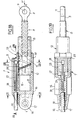
- the mechanical jack 7 comprises a screw 8, one end 9 of which is pierced with a buttonhole 11, so that it can be articulated on the movable part to adjust, or on the fixed part, and a nut 12 pierced with an axial housing 13 having a thread 14 adapted to cooperate with the thread 15 of the screw 8.
- the nut 12 is itself housed in a housing or body 16 secured to one of the two fixed and movable parts by a terminal lug 17 pierced with a buttonhole 18.
- an axial housing 19 receiving the nut 12, and the wall of the housing 19 has a thread 21 adapted to cooperate with threads 22 complementary to the nut 12 formed outside thereof, so as to allow the nut 12 to rotate inside the housing 16 around the general axis XX of the mechanical actuator 7, under conditions which will be specified below.
- the threads 22 are three in number.
- the device 7 is equipped with means for locking and unlocking the nut 12 in accordance with the invention, making it possible to block the latter in rotation as well as the screw 8 in translation, or on the contrary to release the nut 12 in rotation and thus allow a displacement in axial translation of the screw 8 inside the nut 12.
- the screw 8 being articulated by its end 9 on a movable or fixed part, cannot rotate around of its axis XX, so that, when this screw 8 is subjected to an axial thrust F, it can only move in axial translation in the nut 12 only if the latter is free to rotate.
- these means for locking the nut 12 comprise: a portion of locking cylinder 23 provided with internal threads 24, 25, 26 combined with the threads 22 of the nut 12 (therefore also 3 in this example), and in these two series of threads 22-26 are made respective grooves 22a; 24a, 25a, 26a complementary, parallel to the axis XX.
- the locking cylinder 23 is housed in a longitudinal compartment 27 of the housing 16, extending parallel to the housing 19.
- the internal thread 21 is interrupted over an angular sector equal to that occupied by the locking cylinder portion 23, as seen in Figure 23.
- the locking cylinder 23 is in an axial position such that its threads 24-26 are in the radial extension of the threads of the thread 21, the threads 24-26 form with those -this a single thread. This therefore allows the rotation of the nut 12 as well as its axial displacement in the housing 16 by cooperation of its threads 22 with the thread 21 put in phase with the threads 24-26.
- the locker 23 is biased by an elastic member 28, constituted by a helical spring coaxial with a cable 29, one end of which is made integral with the locker 23 by a stop 31 disposed in a corresponding recess of the locker 23.
- the cable 29 thus extends in the compartment 27 and passes through the body 16 outside of which it is wrapped in a sheath 32.
- the cable 29 is provided at its end opposite to the stop 31 with a control element (not shown), for example a manual handle.
- the spring 28 is supported on a bottom of the compartment 27 and exerts on one end of the locker 23 a thrust substantially parallel to the axis XX, which tends to keep the locker 23 in axial abutment against a retaining means such as a rod 33 partially housed in a corresponding gorge of the periphery of the housing 16.
- the housing 27 is dimensioned so as to allow alternating axial displacements of the locker 23 and to guide these displacements by its walls (FIG. 19).
- the operation of the adjustment device 7 is as follows:
- an axial thrust F on the screw 8 results in a double movement: the screw 8 causes the rotation of the nut 12 inside which it sinks by cooperation of threads 14 and 15, and nut 12 performs an axial translation in the housing 16 inside which it sinks.
- the axial movements of the locker 23 are guided by the longitudinal walls of the housing 27 (FIG. 3) and likewise the movements of the cable 29 are guided by a corresponding housing on the surface of the locker 23.
- Figure 24 illustrates an example of application of the quick adjustment device to the adjustment of the components of a seat, which can be that of a vehicle (cars, planes, boats), or of any fixed installation.
- This seat comprises a frame 1 consisting of a back frame 2, a seat 3 on which the frame 2 is articulated, two slides lateral 4, each connected to the seat 3 by two links 5 articulated on the seat 3 and on the slides 4, the latter being mounted sliding in slides 6 fixed to the floor 35.
- the frame 1 is equipped with several linear adjustment devices constituting as many mechanical jacks allowing the adjustment of the three constituent elements of the seat: two jacks 7a are articulated, on the one hand on the lower ends of the frame 2, and on the seat 3 to allow adjustment of the inclination of the frame 2 and therefore of the backrest, two jacks 7b are articulated, on the one hand on the fixed slides 6 and on the other hand on the movable slides 4 in order to allow the adjustment of the longitudinal position of the seat 3 on the floor, and two jacks 7c are articulated, on the one hand on the movable slides 4, and on the other hand on the seat 3 to allow the height adjustment of this last.
- the casings of the jacks 7a are articulated on the seat 3 around an axis perpendicular to the screw so as to be able to tilt around this axis to follow the angular movements of the backrest 2 on which the screw is articulated. Conversely, the latter can be articulated on the seat 3 and the housing on the backrest 2.
- the casings of the jacks 7c are adapted to be articulated on the slides 4 integral with the seat 3 and which can slide in the fixed slides 6, while the screws are articulated on the seat 3, in order to allow the height of the seat 3 above the floor 35.
- this arrangement can be reversed, the screws being articulated on the slides 4 and the housings articulated on the seat 3.
- the casings of the jacks 7b can be secured with the fixed slides 6 and the screws secured with the seat 3, in order to allow the longitudinal adjustment of the latter.
- the screws can be secured to the fixed slides 6, while the boxes are secured to the seat 3.
- FIGs 25 to 27 illustrate the installation of an adjustment device 7, therefore in accordance with the embodiment of Figures 18 to 23, by a fastener 20 on a slide 36 which can slide on a slide 37 fixed to a floor, for example vehicle, for adjusting the longitudinal position of the seat (not shown) of the seat, the cylinder 7 being positioned at the front of the seat.
- the screw 8 is shown in its position for maximum output from the nut 12, itself in its position for maximum output from the housing 16.
- the end 9 of this screw is articulated on two angles 39, 41 secured to the fixed slide 37, for example by rivets 42.
- Rolling balls 43 are conventionally interposed between the slides 36 and 37.
- FIG. 28 illustrates the application of a device 163 to the adjustment of the guide 164 of a table 165 of a woodworking machine, equipped for example with a circular saw 166, or a router, or a jointer, etc. .
- the adjustment of the guide 164 has been ensured by a buttonhole and tightening by nut system, which is advantageously replaced by the device 163.
- This is of the type of FIG. 3, therefore with two screws 167, 168 and provided with a locking system 169 with manual actuation lever 170.
- the screw 167 is articulated on a link 171 itself articulated at its opposite end on an ear 172 of the guide 164.
- the screw 168 and a second link 173 are articulated on a second ear 174 of the guide 164, the opposite end of the link 173 being articulated around a pivot fixed 175, the pivot 176 of articulation of the screw 167 and of the link 171 also being fixed on the table 165.
- the articulation points 172, 174, 175 and 176 constitute the vertices of a parallelogram of which two 175 and 176 are fixed, the other two being movable when the system 169 is unlocked.
- the locking system 169 is arranged to be able to block the rotation of the nut associated with the rods 167, 168, this nut then being suitably provided with an external thread which can come into engagement with that of the locking system 169.
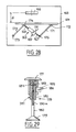
- FIG. 29 shows the application of the quick adjustment device to the height adjustment of the seat 177 of a stool 178, the foot of which consists of a disc 179 resting on the ground and a screw 180.
- ci is part of an adjustment device of the type of that of Figure 2, which therefore comprises a nut 181 having a thread which cooperates with the thread 180a of the screw 180, and a thread 182 cooperating with the thread of a housing 183 carrying at its upper end the seat 177.
- a spring 184 is housed in the housing 183, bearing on the nut 181 and exerting on the seat 177 a vertical thrust directed upwards.
- the device is completed by a locking system 185, arranged to be able to lock the nut 181 in rotation.
- the housing 183 is unlocked relative to the nut 181 by operating the lever 186 of the locking system 185.
- the spring 184 pushes up the seat 177 and the housing 183, which drives the nut 181 in rotation in the upward direction, since the efficiency of the system constituted by the threaded nut 181 and the threaded housing 183 is reversible.
- the foot 179, 180 remaining fixed, the seat 177 therefore travels upwards the pitch of said seat relative to the nut 181, increased by the pitch of the latter relative to the screw 180.
- the seat 177 moves twice as fast as the nut 181.
- the seat 177 and the entire device are locked in the chosen position by operating the locking system 185, which stops the rotation of the nut 181.
- the locking system 185 essentially comprises a shoe provided with a thread which cooperates with the thread 182 and can be moved away from the latter by the manual lever 186.
- the quick adjustment device allows the moving part to be locked in the chosen position by a relatively low force compared to those supported by the device.
- Figure 30 thus illustrates the application of this locking system to a device of the type of that of Figure 1:
- the screw 187 passes through a threaded nut 188 and provided with an external thread 189 of axially fluted zero helix angle, the splines of which can cooperate with the complementary splines of threads 190 of a cylindrical locker 191.
- the latter and the nut 188 are housed in a body or housing 192 on one end 192a of which the locker 191 is biased in abutment by a spring 193 coaxial with a cable 194 provided with a terminal stop 195 housed in a recess of the locker 191.
- the nut 188 is mounted in the housing 192 on ball tracks 196.
- Figure 31 shows a quick adjustment device with two screws 197a, 197b associated with a common nut 198 mounted on ball tracks 199 in a housing 200 of which a protrusion 201 serves as a stop for the locker 191 pushed by the spring 193 inside the housing 200.
- the locker 191 similar to that of FIG. 30, is provided with an axially grooved internal thread 190 which cooperates with a grooved external thread 202 of the nut 198, the inclination of the threads of the thread 202 being zero.
- the housing 155 is then tapped and receives the locking cylinder, and the central portion of the screw 150 is threaded so as to be able to cooperate with the locking cylinder.
Landscapes
- Engineering & Computer Science (AREA)
- Mechanical Engineering (AREA)
- General Engineering & Computer Science (AREA)
- Aviation & Aerospace Engineering (AREA)
- Transportation (AREA)
- Transmission Devices (AREA)
- Flexible Shafts (AREA)
- Vehicle Body Suspensions (AREA)
- Seats For Vehicles (AREA)
Applications Claiming Priority (2)
| Application Number | Priority Date | Filing Date | Title |
|---|---|---|---|
| FR8614179A FR2605075B1 (fr) | 1986-10-13 | 1986-10-13 | Systeme de verrouillage d'un dispositif lineaire de reglage rapide et de blocage d'une piece mobile par rapport a une piece fixe |
| FR8614179 | 1986-10-13 |
Publications (2)
| Publication Number | Publication Date |
|---|---|
| EP0265316A1 true EP0265316A1 (de) | 1988-04-27 |
| EP0265316B1 EP0265316B1 (de) | 1990-05-30 |
Family
ID=9339781
Family Applications (1)
| Application Number | Title | Priority Date | Filing Date |
|---|---|---|---|
| EP87402233A Expired - Lifetime EP0265316B1 (de) | 1986-10-13 | 1987-10-07 | Verriegelungssystem für eine lineare Schnellverstell- und Blockiereinrichtung eines beweglichen Teiles gegenüber einem festen Teil |
Country Status (9)
| Country | Link |
|---|---|
| US (1) | US4782715A (de) |
| EP (1) | EP0265316B1 (de) |
| JP (1) | JPS63214553A (de) |
| BR (1) | BR8705428A (de) |
| CA (1) | CA1286893C (de) |
| DE (1) | DE3762988D1 (de) |
| ES (1) | ES2015592B3 (de) |
| FR (1) | FR2605075B1 (de) |
| MX (1) | MX169768B (de) |
Cited By (3)
| Publication number | Priority date | Publication date | Assignee | Title |
|---|---|---|---|---|
| EP0493198A1 (de) * | 1990-12-26 | 1992-07-01 | Bertrand Faure Automobile "B.F.A." | Schraubstellvorrichtung mit einem ausgesparten schwenkbaren Kern |
| FR2976040A1 (fr) * | 2011-06-06 | 2012-12-07 | Messier Bugatti Dowty | Actionneur telescopique. |
| EP4060206A1 (de) * | 2021-03-17 | 2022-09-21 | Reel | Mechanische vorrichtung zum blockieren einer linearen bewegung zwischen zwei strukturen |
Families Citing this family (27)
| Publication number | Priority date | Publication date | Assignee | Title |
|---|---|---|---|---|
| DE4405992C2 (de) * | 1994-02-24 | 1996-01-25 | Sifa Sitzfabrik Gmbh | Ruckhemmung |
| US5582461A (en) * | 1994-06-17 | 1996-12-10 | Itt Automotive, Inc. | Infinitely adjustable linear actuator |
| US5556165A (en) * | 1994-06-17 | 1996-09-17 | Pickles; Joseph | Infinitely adjustable linear actuator for vehicle seat |
| DE19529255C2 (de) * | 1995-05-05 | 2000-12-21 | Erwin Hoelle | Arretier- und Verstelleinrichtung |
| US5607032A (en) * | 1995-06-07 | 1997-03-04 | Itt Automotive, Inc. | Rotatable shaft lock apparatus |
| US5689995A (en) * | 1996-02-01 | 1997-11-25 | P. L. Porter Co. | Actuator that adjusts to side loads automatically by pivoting internally |
| US5941130A (en) * | 1998-04-07 | 1999-08-24 | General Motors Corporation | Adjustable steering column for motor vehicle |
| EP1175311A1 (de) * | 1999-04-20 | 2002-01-30 | P.L. Porter Co. | System zum steuern einer elektrischen betätigung durch öffnen einer mechanischen verriegelung für fahrzeugteile |
| FR2810000B1 (fr) * | 2000-06-09 | 2004-05-28 | Faure Bertrand Equipements Sa | Siege de vehicule presentant une assise reglable en hauteur |
| FR2845953B1 (fr) | 2002-10-18 | 2005-12-16 | Cresystem | Dispositif de verrouillage de la configuration d'un equipement tel qu'un siege de vehicule |
| GB2401161B (en) * | 2003-05-02 | 2006-09-06 | Titus Internat Ltd | Improvements in movement controls |
| US8677562B2 (en) * | 2003-05-02 | 2014-03-25 | William Ernest Taylor Vallance | Movements controlling means |
| US7556594B2 (en) * | 2005-01-04 | 2009-07-07 | Houston Vincent J | Fitness device |
| DE112006000287A5 (de) * | 2005-02-23 | 2007-10-31 | Luk Lamellen Und Kupplungsbau Beteiligungs Kg | Betätigungsvorrichtung für ein Kraftfahrzeug-Getriebe, sowie Verfahren zur Verminderung oder Vermeidung von massenträgheitsbedingten Steuerungsfehlern bei Gangwechselvorgängen |
| US7587956B2 (en) * | 2006-08-29 | 2009-09-15 | Franklin Products, Inc. | Device for controlling motion |
| DE102013202700A1 (de) * | 2012-03-12 | 2013-09-12 | Schaeffler Technologies AG & Co. KG | Planetenwälzgetriebe und Hydrostataktor mit diesem |
| CN103441608A (zh) * | 2013-08-06 | 2013-12-11 | 中国航天科技集团公司第九研究院第七七一研究所 | 一种电动缸防转机构 |
| CN103441607B (zh) * | 2013-08-06 | 2016-08-10 | 中国航天科技集团公司第九研究院第七七一研究所 | 一种矩形缸体电动缸的内防转机构 |
| ES2550369B1 (es) * | 2014-05-05 | 2016-07-21 | Mespack, Sl | Dispositivo automático de cambio de formato para máquina horizontal automática formadora y llenadora de envases flexibles |
| DE102014219256B4 (de) * | 2014-09-24 | 2016-05-04 | Schaeffler Technologies AG & Co. KG | Kugelgewindetrieb |
| CA2994675C (en) * | 2015-08-04 | 2024-04-09 | Kyntec Corporation | Mechanical spring actuator |
| US10081325B2 (en) * | 2016-03-07 | 2018-09-25 | Philadelphia Toboggan Coasters, Inc. | Splined lap bar assembly for amusement ride car |
| GB2552509A (en) * | 2016-07-26 | 2018-01-31 | Truck Align London Ltd | Lead screw mechanism |
| DE102018127297B4 (de) * | 2018-10-31 | 2022-03-17 | Witte Automotive Gmbh | Schließbügelanordnung und Verriegelungsvorrichtung |
| US11530561B2 (en) * | 2020-05-13 | 2022-12-20 | Microsoft Technology Licensing, Llc | Variable friction hinged device |
| CN114427804B (zh) * | 2022-02-07 | 2023-08-29 | 四川中陆嘉诚科技有限公司 | 一种用于发射车的自动式射击固定器 |
| CN116624825B (zh) * | 2023-07-25 | 2023-09-26 | 常州星宇车灯股份有限公司 | 三个方向可调的固定结构 |
Citations (5)
| Publication number | Priority date | Publication date | Assignee | Title |
|---|---|---|---|---|
| US2524481A (en) * | 1941-12-19 | 1950-10-03 | Schermuly Conrad David | Drift release mechanism for presses |
| US2933939A (en) * | 1958-12-01 | 1960-04-26 | Gen Motors Corp | Free wheeling ball nut and screw assembly |
| US3043552A (en) * | 1960-03-03 | 1962-07-10 | Gen Motors Corp | Power transmitting mechanism for vehicle seats |
| DE1185441B (de) * | 1957-04-03 | 1965-01-14 | English Electric Co Ltd | Verriegelbare Fuehrungsspindel |
| DE2943694A1 (de) * | 1979-10-30 | 1981-05-14 | Robert Dr.-Ing. 6308 Butzbach Gärtner | Stelleinrichtung mit spindeltrieb |
Family Cites Families (11)
| Publication number | Priority date | Publication date | Assignee | Title |
|---|---|---|---|---|
| US2579305A (en) * | 1948-01-26 | 1951-12-18 | Sturgess Inc | Position-adjusting mechanism |
| US3046055A (en) * | 1960-02-19 | 1962-07-24 | Anderson Co | Position-adjusting mechanism |
| US3127788A (en) * | 1960-12-29 | 1964-04-07 | Anderson Co | Position-retaining device |
| DE1429262C3 (de) * | 1963-07-25 | 1974-08-29 | The Anderson Co., Gary, Ind. (V.St.A.) | Einrichtung zum Festlegen der Stellung der einstellbaren Rückenlehne eines Sessels |
| US3246868A (en) * | 1964-07-14 | 1966-04-19 | Anderson Co | Position-retaining device |
| US3356411A (en) * | 1965-02-18 | 1967-12-05 | Lear Siegler Inc | Seat back positioning mechanism |
| US3398986A (en) * | 1966-12-08 | 1968-08-27 | Lear Siegler Inc | Seat positioning mechanism |
| US3436973A (en) * | 1967-06-19 | 1969-04-08 | Kamal Y Aweimrine | Mechanical lock cylinder |
| US3479890A (en) * | 1967-06-29 | 1969-11-25 | Fairchild Hiller Corp | Seat reclining mechanism |
| US4589301A (en) * | 1983-04-27 | 1986-05-20 | Hoover Universal, Inc. | Linearly infinitely variable mechanism |
| GB8406697D0 (en) * | 1984-03-14 | 1984-04-18 | Teleflex Morse Ltd | Seat recline unit |
-
1986
- 1986-10-13 FR FR8614179A patent/FR2605075B1/fr not_active Expired
-
1987
- 1987-10-07 DE DE8787402233T patent/DE3762988D1/de not_active Expired - Fee Related
- 1987-10-07 ES ES87402233T patent/ES2015592B3/es not_active Expired - Lifetime
- 1987-10-07 EP EP87402233A patent/EP0265316B1/de not_active Expired - Lifetime
- 1987-10-09 BR BR8705428A patent/BR8705428A/pt not_active IP Right Cessation
- 1987-10-13 MX MX008819A patent/MX169768B/es unknown
- 1987-10-13 JP JP62256419A patent/JPS63214553A/ja active Pending
- 1987-10-13 CA CA000549132A patent/CA1286893C/en not_active Expired - Fee Related
- 1987-10-13 US US07/107,696 patent/US4782715A/en not_active Expired - Fee Related
Patent Citations (5)
| Publication number | Priority date | Publication date | Assignee | Title |
|---|---|---|---|---|
| US2524481A (en) * | 1941-12-19 | 1950-10-03 | Schermuly Conrad David | Drift release mechanism for presses |
| DE1185441B (de) * | 1957-04-03 | 1965-01-14 | English Electric Co Ltd | Verriegelbare Fuehrungsspindel |
| US2933939A (en) * | 1958-12-01 | 1960-04-26 | Gen Motors Corp | Free wheeling ball nut and screw assembly |
| US3043552A (en) * | 1960-03-03 | 1962-07-10 | Gen Motors Corp | Power transmitting mechanism for vehicle seats |
| DE2943694A1 (de) * | 1979-10-30 | 1981-05-14 | Robert Dr.-Ing. 6308 Butzbach Gärtner | Stelleinrichtung mit spindeltrieb |
Cited By (7)
| Publication number | Priority date | Publication date | Assignee | Title |
|---|---|---|---|---|
| EP0493198A1 (de) * | 1990-12-26 | 1992-07-01 | Bertrand Faure Automobile "B.F.A." | Schraubstellvorrichtung mit einem ausgesparten schwenkbaren Kern |
| FR2671203A1 (fr) * | 1990-12-26 | 1992-07-03 | Faure Bertrand Automobile | Verin de positionnement a vis et a noyau pivotant evide. |
| FR2976040A1 (fr) * | 2011-06-06 | 2012-12-07 | Messier Bugatti Dowty | Actionneur telescopique. |
| EP2532583A3 (de) * | 2011-06-06 | 2012-12-26 | Messier-Bugatti-Dowty | Teleskopstellglied |
| US8794088B2 (en) | 2011-06-06 | 2014-08-05 | Messier-Bugatti-Dowty | Telescopic actuator |
| EP4060206A1 (de) * | 2021-03-17 | 2022-09-21 | Reel | Mechanische vorrichtung zum blockieren einer linearen bewegung zwischen zwei strukturen |
| FR3120926A1 (fr) * | 2021-03-17 | 2022-09-23 | Reel | Dispositif de blocage mecanique d’un mouvement lineaire entre deux structures |
Also Published As
| Publication number | Publication date |
|---|---|
| FR2605075B1 (fr) | 1989-01-27 |
| ES2015592B3 (es) | 1990-09-01 |
| DE3762988D1 (de) | 1990-07-05 |
| US4782715A (en) | 1988-11-08 |
| MX169768B (es) | 1993-07-26 |
| CA1286893C (en) | 1991-07-30 |
| JPS63214553A (ja) | 1988-09-07 |
| FR2605075A1 (fr) | 1988-04-15 |
| BR8705428A (pt) | 1988-05-24 |
| EP0265316B1 (de) | 1990-05-30 |
Similar Documents
| Publication | Publication Date | Title |
|---|---|---|
| EP0265316A1 (de) | Verriegelungssystem für eine lineare Schnellverstell- und Blockiereinrichtung eines beweglichen Teiles gegenüber einem festen Teil | |
| EP0265317A1 (de) | Vorrichtung zur Schnellverstellung und Blockierung eines linear bewegten Teiles, insbesondere anwendbar für die Tischführung an Holzbearbeitungsmaschinen | |
| EP0694434B1 (de) | Gelenkbeschlag für Fahrzeugsitz | |
| FR2835790A1 (fr) | Dispositif de calage vertical et automatique d'un siege de vehicule | |
| EP0723889B1 (de) | Fahrzeugsitzgleitschiene | |
| EP0687590B1 (de) | Verriegelung eines verschiebbaren Gegenstandes wie z.B. einer Kopfstütze | |
| FR2822419A1 (fr) | Siege de vehicule equipe d'un mecanisme d'articulation | |
| CA2289718C (fr) | Siege tournant, notamment pour vehicule ferroviaire | |
| FR2746065A1 (fr) | Appui-tete pour siege de vehicule automobile | |
| FR2766139A1 (fr) | Dispositif d'articulation pour siege de vehicule, et siege de vehicule comportant un tel dispositif | |
| FR2774045A1 (fr) | Siege pour vehicule, amovible, retournable et reglable longitudinalement | |
| FR2927027A1 (fr) | Mecanisme d'articulation a elements de verrouillage pivotant pour siege de vehicule et siege comportant un tel mecanisme | |
| FR2963586A1 (fr) | Glissiere pour siege de vehicule automobile a verrouillage lateral sans jeu | |
| FR2841838A1 (fr) | Siege de vehicule equipe d'un mecanisme d'articulation | |
| FR2525001A1 (fr) | Dispositif pour le reglage progressif des positions relatives de deux organes mutuellement deplacables | |
| FR2747079A1 (fr) | Siege de vehicule, deplacable vers l'avant pour acceder a un espace arriere | |
| FR2884191A1 (fr) | Mecanisme d'articulation pour siege de vehicule et siege equipe d'un tel mecanisme | |
| FR2487652A1 (fr) | Mecanisme d'articulation reglable, notamment pour dossier de siege | |
| FR2527060A1 (fr) | Ensemble pour siege reglable a deux mecanismes de commande independants | |
| CH629106A5 (fr) | Fixation de securite pour ski. | |
| EP0263003B1 (de) | Gelenk, welches eine Entkupplung über einen bestimmten Winkelwert erlaubt und eine grosse Verstellung der Rückenlehne gegenüber der Sitzfläche eines Sitzes zulässt | |
| FR2882539A1 (fr) | Dispositif pour actionner simultanement deux elements et siege comprenant un tel dispositif | |
| EP3350016B1 (de) | Verriegelungsvorrichtung für zwei positionen einer hintersitz-rückenlehne eines kraftfahrzeugs | |
| FR2750185A1 (fr) | Mecanisme pour commander un organe de sortie rotatif au moyen d'un poignee, et siege comportant un tel mecanisme | |
| FR2531895A1 (fr) | Cle de serrage |
Legal Events
| Date | Code | Title | Description |
|---|---|---|---|
| PUAI | Public reference made under article 153(3) epc to a published international application that has entered the european phase |
Free format text: ORIGINAL CODE: 0009012 |
|
| AK | Designated contracting states |
Kind code of ref document: A1 Designated state(s): DE ES GB IT SE |
|
| 17P | Request for examination filed |
Effective date: 19880909 |
|
| 17Q | First examination report despatched |
Effective date: 19890106 |
|
| GRAA | (expected) grant |
Free format text: ORIGINAL CODE: 0009210 |
|
| AK | Designated contracting states |
Kind code of ref document: B1 Designated state(s): DE ES GB IT SE |
|
| GBT | Gb: translation of ep patent filed (gb section 77(6)(a)/1977) | ||
| REF | Corresponds to: |
Ref document number: 3762988 Country of ref document: DE Date of ref document: 19900705 |
|
| ITF | It: translation for a ep patent filed |
Owner name: FUMERO BREVETTI S.N.C. |
|
| RAP2 | Party data changed (patent owner data changed or rights of a patent transferred) |
Owner name: ROCKWELL AUTOMOTIVE BODY SYSTEMS-FRANCE EN ABREGE: |
|
| PLBE | No opposition filed within time limit |
Free format text: ORIGINAL CODE: 0009261 |
|
| STAA | Information on the status of an ep patent application or granted ep patent |
Free format text: STATUS: NO OPPOSITION FILED WITHIN TIME LIMIT |
|
| 26N | No opposition filed | ||
| PGFP | Annual fee paid to national office [announced via postgrant information from national office to epo] |
Ref country code: DE Payment date: 19910822 Year of fee payment: 5 |
|
| PGFP | Annual fee paid to national office [announced via postgrant information from national office to epo] |
Ref country code: GB Payment date: 19911001 Year of fee payment: 5 |
|
| PGFP | Annual fee paid to national office [announced via postgrant information from national office to epo] |
Ref country code: ES Payment date: 19911004 Year of fee payment: 5 |
|
| PGFP | Annual fee paid to national office [announced via postgrant information from national office to epo] |
Ref country code: SE Payment date: 19911028 Year of fee payment: 5 |
|
| ITTA | It: last paid annual fee | ||
| PG25 | Lapsed in a contracting state [announced via postgrant information from national office to epo] |
Ref country code: GB Effective date: 19921007 |
|
| PG25 | Lapsed in a contracting state [announced via postgrant information from national office to epo] |
Ref country code: SE Effective date: 19921008 Ref country code: ES Free format text: LAPSE BECAUSE OF THE APPLICANT RENOUNCES Effective date: 19921008 |
|
| GBPC | Gb: european patent ceased through non-payment of renewal fee |
Effective date: 19921007 |
|
| PG25 | Lapsed in a contracting state [announced via postgrant information from national office to epo] |
Ref country code: DE Effective date: 19930701 |
|
| EUG | Se: european patent has lapsed |
Ref document number: 87402233.8 Effective date: 19930510 |
|
| REG | Reference to a national code |
Ref country code: ES Ref legal event code: FD2A Effective date: 20001009 |
|
| PG25 | Lapsed in a contracting state [announced via postgrant information from national office to epo] |
Ref country code: IT Free format text: LAPSE BECAUSE OF NON-PAYMENT OF DUE FEES Effective date: 20051007 |