EP0247973B1 - Vorrichtung zur Verhinderung des Vorgarnendabwickelns, angewendet am Vorgarnspulentransportsystem - Google Patents
Vorrichtung zur Verhinderung des Vorgarnendabwickelns, angewendet am Vorgarnspulentransportsystem Download PDFInfo
- Publication number
- EP0247973B1 EP0247973B1 EP87810314A EP87810314A EP0247973B1 EP 0247973 B1 EP0247973 B1 EP 0247973B1 EP 87810314 A EP87810314 A EP 87810314A EP 87810314 A EP87810314 A EP 87810314A EP 0247973 B1 EP0247973 B1 EP 0247973B1
- Authority
- EP
- European Patent Office
- Prior art keywords
- roving
- bobbin
- bobbins
- roving bobbins
- displacing
- Prior art date
- Legal status (The legal status is an assumption and is not a legal conclusion. Google has not performed a legal analysis and makes no representation as to the accuracy of the status listed.)
- Expired - Lifetime
Links
- 238000003825 pressing Methods 0.000 claims description 64
- 238000004804 winding Methods 0.000 claims description 47
- 230000007246 mechanism Effects 0.000 claims description 38
- 238000009987 spinning Methods 0.000 claims description 27
- 230000002093 peripheral effect Effects 0.000 claims description 25
- 239000011295 pitch Substances 0.000 claims description 16
- 230000009471 action Effects 0.000 claims description 5
- 238000006073 displacement reaction Methods 0.000 claims description 2
- 210000000078 claw Anatomy 0.000 description 6
- 230000001105 regulatory effect Effects 0.000 description 6
- 238000010276 construction Methods 0.000 description 5
- 230000000630 rising effect Effects 0.000 description 3
- 238000000034 method Methods 0.000 description 2
- 230000009467 reduction Effects 0.000 description 2
- 238000007665 sagging Methods 0.000 description 2
- 239000000835 fiber Substances 0.000 description 1
- 238000004519 manufacturing process Methods 0.000 description 1
- 230000032258 transport Effects 0.000 description 1
Images


Classifications
-
- D—TEXTILES; PAPER
- D01—NATURAL OR MAN-MADE THREADS OR FIBRES; SPINNING
- D01H—SPINNING OR TWISTING
- D01H9/00—Arrangements for replacing or removing bobbins, cores, receptacles, or completed packages at paying-out or take-up stations ; Combination of spinning-winding machine
- D01H9/18—Arrangements for replacing or removing bobbins, cores, receptacles, or completed packages at paying-out or take-up stations ; Combination of spinning-winding machine for supplying bobbins, cores, receptacles, or completed packages to, or transporting from, paying-out or take-up stations ; Arrangements to prevent unwinding of roving from roving bobbins
-
- B—PERFORMING OPERATIONS; TRANSPORTING
- B65—CONVEYING; PACKING; STORING; HANDLING THIN OR FILAMENTARY MATERIAL
- B65H—HANDLING THIN OR FILAMENTARY MATERIAL, e.g. SHEETS, WEBS, CABLES
- B65H65/00—Securing material to cores or formers
- B65H65/005—Securing end of yarn in the wound or completed package
-
- D—TEXTILES; PAPER
- D01—NATURAL OR MAN-MADE THREADS OR FIBRES; SPINNING
- D01H—SPINNING OR TWISTING
- D01H9/00—Arrangements for replacing or removing bobbins, cores, receptacles, or completed packages at paying-out or take-up stations ; Combination of spinning-winding machine
- D01H9/005—Arrangements for replacing or removing bobbins, cores, receptacles, or completed packages at paying-out or take-up stations ; Combination of spinning-winding machine for removing empty packages or cans and replacing by completed (full) packages or cans at paying-out stations; also combined with piecing of the roving
-
- B—PERFORMING OPERATIONS; TRANSPORTING
- B65—CONVEYING; PACKING; STORING; HANDLING THIN OR FILAMENTARY MATERIAL
- B65H—HANDLING THIN OR FILAMENTARY MATERIAL, e.g. SHEETS, WEBS, CABLES
- B65H2701/00—Handled material; Storage means
- B65H2701/30—Handled filamentary material
- B65H2701/31—Textiles threads or artificial strands of filaments
Definitions
- the present invention relates to an apparatus for preventing an unwinding of an end of a roving when roving bobbins doffed from a roving frame are transported to the vicinity of a creel of a spinning frame or the roving bobbins are mounted to the respective creels of the spinning frame.
- a roving bobbin transporting system As a means for transporting roving bobbins doffed from roving frames to spinning frames, a roving bobbin transporting system has been disclosed (JP-A-60 67368) in which a transporting rail system is arranged between the positions above the roving frames and the positions above the spinning frames, bobbin carriages are movably supported by the transporting rail system, roving bobbins doffed from the flyer frames are suspended from respective bobbin hangers of the bobbin carriages so that the roving bobbins are transported in this suspended condition to the respective positions above the spinning frames.
- a roving bobbin exchange apparatus has been developed so that roving bobbins are automatically exchanged with empty bobbins on the respective spinning creels.
- This apparatus has a function of firmly attaching a free end of a roving to the outer periphery of the winding portion of each roving bobbin, while the roving bobbins, doffed from the respective bobbin wheels of each roving frame, are displaced by a transporting means.
- the present invention relates to an apparatus having a function such that, while full roving bobbins doffed from the respective bobbin wheels of each roving frame are carried by the transporting means, each bobbin is rotated in the winding direction of the roving in a condition such that the peripheral face of the winding portion of each roving bobbin is under pressure by a certain pressing member, whereby the free end of the roving is firmly attached to the periphery of the winding portion of the roving bobbin.
- a transporting system in which the apparatus for preventing an unwinding of the roving end according to the present invention is built, includes various embodiments according to the system for transporting doffed roving bobbins to the spinning frames.
- This transporting system includes an embodiment in which a transporting apparatus having many bobbin hangers is moved along a transporting rail arranged between respective positions above the roving frames and respective positions above the spinning frames, while suspending doffed roving bobbins by respective bobbin hangers so that the doffed roving bobbins are transported from respective positions above roving frames to the respective positions above the spinning frames, and an embodiment in which full bobbins doffed from each roving frame are delivered to corresponding bobbin hangers of the above-mentioned transporting apparatus.
- the latter embodiment includes different modes adopted for the simultaneous doffing method and the method using a wagon type doffer, respectively.
- the transporting system including the apparatus of the present invention, comprises a moving body having supporting members for holding each roving bobbin in a condition such that each roving bobbin is substantially vertically supported, and means for displacing the moving body along a predetermined track, and in this transporting system, the roving bobbins taken out from the respective bobbin wheels of the roving frame are supported by the supporting member while being displaced to predetermined positions.
- the apparatus of the present invention comprises, in principle, a pressing member disposed in the vicinity of the predetermined track of this transporting system to apply pressure to the peripheral face of the winding portion of each roving bobbin and a mechanism for rotating the roving bobbin in the winding direction of a roving under the pressing action of the pressing member.
- the apparatus for preventing the unwinding of an end of a roving of each roving bobbin according to the present invention is characterized in that pressure is applied to the peripheral face of a roving bobbin by the pressing member, and the roving bobbin is rotated in the winding direction of the roving by the bobbin-rotating mechanism under the above mentioned pressure, whereby the roving end of the roving bobbin is pressed against the winding portion of the roving bobbin and firmly attached thereto, said pressing member being disposed at a position adjacent to said predetermined track for transporting said roving bobbins, and thus the above-mentioned problems are satisfactorily solved.
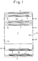
- a plurality of roving frames 1 and a plurality of spinning frames are arranged according to the production capacity of the mill.
- a simultaneous doffing apparatus 3 is disposed in front of each roving frame 1.
- This simultaneous doffing apparatus 3 is constructed so that all the roving bobbins 4 of each roving frame 1 are simultaneously doffed from the respective bobbin wheels of the roving frame and then mounted on a peg 5a of the peg conveyor 5 as shown in Fig. 2.
- the structure of this simultaneous doffing apparatus 3 is illustrated, for example, in Japanese Unexamined Patent Publication No. 57-106729, USP 4,369,621, GBP 2,089,379 or WGP 3,146,040.
- the specific structure of the simultaneous doffing apparatus is not particularly critical and, accordingly, an explanation thereof is omitted.
- An overhead roving bobbin transporting system 6 transports roving bobbins 4 doffed by the simultaneous doffing apparatus 3 to a corresponding spinning frame 2, and this transporting system 6 has the following construction. That is, a transporting rail 7 is arranged in a space between the roving frame-setting position 1A and the spinning frame-setting position 2A.
- the transporting rail 7 comprises branch rails 7b arranged along the respective roving frames 1 and spinning frames 2 and a main rail 7a connecting these branch rails 7b.
- the rails 7a and 7b are supported by brackets secured to the machine stands or ceiling.
- Each bobbin carriage 11 comprising a plurality of carrying members 10 is suspended on the transporting rail 7 so that each bobbin carriage 11 can move along the transporting rail 7.
- each carrying member 10 supporting levers 14 are secured to a carriage bar 12, and wheels (not shown) rotatably supported on both sides of a bearing portion (not shown) of the supporting lever 14 are placed on the supporting face of the transporting rail 7.
- bobbin hangers 16 are mounted at predetermined pitches P in the longitudinal direction of the carriage bar 12, and indexing pins 17 are secured to the upper face of the carriage bar 12 at pitches two times the attachment pitches P of the bobbin hangers 16, so that the indexing pins 17 expand from both edges of the carriage bar 12.
- a plurality of such carrying members 10 are connected by connecting bars 18 and connecting pins 19 so that the line of the carrying members 10 can be bent and the pitches between every two adjacent carrying members 10 are equal to the pitches P.
- the pitches P of the bobbin hangers 16 are adjusted to 2 times the spindle pitches in the spinning frame 2.
- a displacing device 20 for mounting the roving bobbins 4 doffed by the simultaneous doffing apparatus 3 to the respective bobbin hangers 16 of the bobbin carriage 11, comprises a bobbin transfer device 21 which is disposed in the vicinity of one end of the peg conveyor 5 so as to receive doffed roving bobbins 4 on the respective pegs 32 of a device 22 for lifting these received roving bobbins 4 to the respective bobbin hangers 16.
- the bobbin transfer device 21 comprises a pair of arms 23 mounted on a frame 21a of the device 21 in rotatable condition of predetermined angle and a plurality of holding claws 25 which are vertically movably supported on the top ends of the arms 23 which is actuated by a pneumatic cylinder 24 mounted on the device 21.
- These holding claws 25 can be opened and closed by a cylinder (not shown in the drawings).
- the top ends of the roving bobbins 4 supported by the pegs 5a of the peg conveyor 5 are held by these holding claws 25 and, thereafter, the roving bobbins 4 are taken from the pegs 5a, and the roving bobbins 4 are mounted on respective pegs 32, described below, of the lifting device 22.
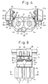
- the roving end unwinding-preventing apparatus of the present invention is built in a part of mechanical elements constituting the lifting device 22, as shown in Figs. 3 and 4.
- a pair of vertical guide rails 26 are secured to left and right frames 22a.
- a lifter 27 is guided by the guiding rails 26, and the lifter 27 has a function of displacing roving bobbins upwards or downwards between two positions, that is a position for receiving doffed roving bobbins 4 by the respective pegs 32 and another position for transferring the above-mentioned roving bobbins 4 to the respective bobbin hangers 16 of the bobbin carriage 11.
- the pegs 32 function as members for supporting the respective roving bobbins
- the lifter 27 functions as a displacing body for displacing the respective supporting members, that is the pegs 32.
- a pair of guiding rollers 28 and a pair of regulating rollers 29 are rotatably attached to upper and lower parts of both the end portions of the lifter 27 through brackets.
- the guide rails 26 are held between the guiding rollers 28 and the regulating rollers 29 abut against the guiding rails 26 to maintain the posture of the lifter 27.
- This lifter 27 can be moved up and down by a predetermined distance by an appropriate lift mechanism operated by a pneumatic cylinder or motor, for example, a mechanism disclosed in Japanese Unexamined Patent Publication No. 58-41919.
- a pair of pegs 32 are rotatably mounted on the lifter 27 through bearings or the like in condition such that they project upwards, and when the lifter 27 is displaced to the uppermost position, the pegs 32 can be positioned to vertically confront two bobbin hangers 16 of the bobbin carriage 11 guided by the transporting rail 7.
- Each peg 32 is formed so that it can be inserted into the lower aperture of each roving bobbin 4 and each peg 32 has a receiving part 33 for receiving the lower face of the mounted roving bobbin 4.
- the pressing device and a part of the mechanism for revolving the pegs 32 are symmetrically disposed to the respective pegs 32 of the lifter 27, respectively.
- a pressing device 34 is mounted on the lifter 27 in a condition such that it is capable of pressing against the peripheral face of the roving bobbin 4 supported by the respective pegs 32.
- This pressing device 34 is provided with a plate spring 35 having a free end, and the base portion (lower portion) of the plate spring 35 is secured to the lifter 27 and a pressing portion 35a is formed on the top end of the plate spring 35 so that, in the natural state, the pressing portion 35a is capable of pressing against the peripheral face of the roving bobbin 4 mounted on the peg 32.
- an engaging piece 36 having a engaging aperture 36a extending in the vertical direction is integrally secured to the top end of the plate spring 35.
- a releasing pin 37 is secured to a frame 22a of the lifting device 22 as the engaging member, and the engaging pin 37 is formed in a tapered shape so that by the engagement of the releasing pin 37 with the engaging aperture 36a, the pressing portion 35a of the plate spring 35 is deformed to a withdrawn position separated from the peripheral face of the roving bobbin 4.
- the other engaging pin (not shown) is disposed at the upper position of the frame 22a of the lifting device and facing the releasing pin 37.
- This mechanism has a function such that, before the roving bobbins 4 are transferred to the respective bobbin hangers 16, the contact pressure of the plate spring 35 against the peripheral surface of the winding portion 4a of each roving bobbin 4 is eliminated.
- the engaging pin 37 may be a wedge piece or cam plate secured to the frame 22a, and in this case, an engaging piece is arranged on the plate spring 35 so that, when the lifter 27 is brought down, the engaging piece becomes engaged with the wedge piece or cam plate to displace the top end of the plate spring 35 outward.
- a bobbin-rotating mechanism 38 for revolving each peg 32 is secured to the frame of the lifter 27 for rotating the roving bobbin 4 mounted on the peg 32 in the winding direction of roving.
- This bobbin-rotating mechanism 38 is provided with a driving motor 39 secured to the lifter 27, and a pulley 40 is secured to a driving shaft 39a of the driving motor 39.
- a pulley 41 which works as an element of the bobbin-rotating mechanism 38, is formed integrally with the peg 32, and a belt 42 is led between this pulley 41 and the pulley 40.
- a dog (not shown) is integrally formed on the lifter 27 to actuate an upper limit switch (not shown) and a lower limit switch (not shown) at the falling and rising positions of the lifter 27, respectively.
- the driving motor 39 is arranged so that, when the lifter 27 rises and the dog separates from the lower limit switch, the driving motor 39 is rotated and driven, and when the dog actuates the upper limit switch, the driving motor 39 is stopped.
- a feeding device 49 intermittently displaces the bobbin carriage 11 for a predetermined distance along the transporting rail 7. Since the detailed mechanism and function of this device 49 are disclosed in the Japanese Examined Utility Model Application Showa 61-3896, the construction and function of this device are hereinafter only briefly explained.
- a main body 50 of this device is secured to the transporting rail 7, and a driving shaft (now shown) is rotatably mounted on the main body 50.
- a brake motor 54 is mounted on the main body 50, and this brake motor 54 is provided with a speed reduction mechanism.
- a chain 56 is laid on a chain wheel secured to an output shaft 55 of the brake motor 54 and a chain wheel (not shown) secured to the above-mentioned driving shaft, so that this driving shaft can be rotated in a predetermined direction.
- cranks are arranged in an almost horizontal condition respectively, and free end portions of these two cranks are connected to one of the cross-riders 58, respectively, which are supported on both sides of the main body 50 in a horizontal condition, respectively.
- the doffing machine 3 simultaneously doffs the roving bobbins 4 on the pegs 5a of the peg conveyor 5 from the roving frame 1. Then, the roving bobbins 4 on the peg conveyor 5 are displaced toward the bobbin-displacing device 20, and at the position where the first two roving bobbins 4 confront the holding claws 25 of the bobbin transfer device 21, the movement of the peg conveyor 5 is stopped.
- the holding claws 25 hold the top ends of the roving bobbins 4 and take the roving bobbins 4 from the pegs 5, and the claws 25 mount the roving bobbins 4 on the pegs 32 of the lifter 27 in the falling condition in the lifting device 22.
- the following action of the pressing device 34 is created for each peg 32, that is, the engaging aperture 36a of the engaging piece 36 in the pressing device 34 is engaged with the engaging pin 37 and the pressing portion 35a of the plate spring 35 is located outside the roving bobbin-present region on the lifter 27. Accordingly, the roving bobbins 4 can be easily mounted on the pegs 32 without coming in to contact with the pressing portions 35a (see Fig. 3).
- the driving motor 39 of the bobbin-rotating mechanism 38 is stopped in this condition and, therefore, the pegs 32 and the roving bobbins 4 mounted thereon are not rotated.
- the bobbin hangers 16 supported on the transporting rail 7 are moved to the positions confronting the pegs 32 on the lifter 27 and stopped at these positions. Then, the lifter 27 rises and the top ends of the roving bobbins 4 are transfered to the respective bobbin hangers 16 of the bobbin carriage 11.
- the driving motor 39 of the bobbin-rotating mechanism 38 is rotated and driven to rotate the belt 42 in the direction indicated by the arrow (Fig. 4) and rotate the pegs 32 and each roving bobbin 4 mounted thereon in the roving-winding direction.
- the pressing portion 35a of the plate spring 35 is in pressure contact with the peripheral face of the winding 4a of the roving bobbin 4 as mentioned above, the end of the roving is pressed against the winding 4a and firmly attached thereto by the rotation of each roving bobbin 4.
- the two roving bobbins 4 transfered to a pair of the bobbin hangers 16 are displaced forwards in the suspended condition.
- This intermittent movement is effected every time the roving bobbins 4 are transfered to the bobbin hangers 16, and when a predetermined number of roving bobbins 4 are mounted on all the bobbin hangers 16 of the bobbin carriage 11, the bobbin carriage 11 is carried to the respective positions above the spinning frames 2 by a continuous feed device 51 (see Fig. 1), as hereinafter explained.
- Figures 5 and 6 illustrate an embodiment in which the present invention is applied to the wagon type doffing machine disclosed in the specification of Japanese Patent Unexamined Publication No. 61-174432.
- a doffer 60 is arranged movably along the front face of the roving frame 1, and two pairs of peg bars 62 and 63 are mounted on a frame 61 of the doffer 60 so that the peg bars 62 and 63 can be moved in the vertical direction by an appropriate lift mechanism.
- the doffer 60 is provided with a mechanism 66A for transferring roving bobbins 4 received from the respective bobbin wheels of the roving frame 1 to the respective bobbin hangers 16 of the bobbin carriage 11.
- This bobbin transfer mechanism 60A is provided with a pair of peg bars 62, 63 whereon four or six pegs 64, 65, are mounted respectively, and these peg bars 62, 63 are capable of displacing in the vertical direction respectively in relation to the condition thereof by a lifting mechanism mounted on a machine frame 61 of the doffer 60.
- a doffing mechanism 70 is mounted on the frame 61 of the doffer 60 for doffing roving bobbins 4 of the roving frame 1 and mounting them on the respective pegs 64 of the peg bar 62 in the falling condition or taking out empty bobbins 4e mounted on pegs 65 of the peg bar 63 in the falling condition and mounting them on the respective bobbin wheels of the roving frame.
- the peg bar 62 is utilized as a constitutional element of the present invention as a moving body having supporting members for holding roving bobbins, while the peg 64 functions as the above-mentioned supporting member.
- the pegs 64 of the peg bar 62 are rotatably arranged as in the embodiment shown in Figs. 3 and 4 so that only while the peg bar 62 is in the rising condition are each of the pegs 64 revolved in the roving-winding direction of the roving bobbins 4 by a driving motor of a bobbin-rotating mechanism (not shown).
- a pressing member 66 is pivoted on the peg bar 62 at this base portion and the pressing member 66 is urged toward the axial line of the peg 64 by a spring 68 so that the pressing member 66 abuts against a stopper 67. Only while the peg bar 62 is in the falling condition and the rising condition, is the pressing member 66 released from the pressing action thereof by an action of a solenoid 69 as a releasing member, or a cam.
- the pressing surface 66a of the pressing member 66 comes into pressure contact with the peripheries of windings 4a of each roving bobbin 4 while the roving bobbin 4 is rotated in the roving-winding direction, whereby the roving ends can be firmly attached to the windings 4a of all roving bobbins 4.
- the apparatus exerts the intended function during the operation of transporting roving bobbins, where full roving bobbins doffed from the respective bobbin wheels of the roving frame are transported and transfered to the respective bobbin hangers of the bobbin carriage of the above-mentioned overhead type roving bobbin transporting system.
- An embodiment of the present invention applied to the overhead type roving bobbin transporting system, wherein the apparatus of the present invention functions in the time of carrying thee roving bobbins forwards along the transporting rail by displacing the bobbin carriage forwards, will now be described. In this embodiment, the explanation of the mechanism and function of the overhead type roving bobbin transporting system per se is omitted, to avoid duplication.
- FIG. 7 through 9 illustrate an embodiment where the roving end unwinding-preventing apparatus of the present invention is applied to the overhead type roving transporting apparatus shown in Fig. 2 wherein the profile of the apparatus of the present invention is shown by a one-dot chain line.
- a device for pressing the peripheral surface of the winding portion of roving bobbins is arranged in the midway of a passage for transporting roving bobbins 4 by the bobbin carriage 11.
- this device 74 is located at a second stop station in the transporting track from the position of the bobbin hanger 16 where the roving bobbins 4 are transferred by the bobbin-displacing device 20, however, preferably, the device 74 is located at a first stop position.
- a pressing plate 75 is secured to a bracket 71 fixed to the transporting rail 7 through an attachment screw 76, and the pressing plate 75 is located so that the lower end portion of the pressing plate 75 is exposed into the transporting passage for the roving bobbins 4 of the bobbin carriage 11, as shown in Fig. 9.
- a positioning recess 77 in which the peripheral face 4a of the winding portion of each roving bobbin 4 is fitted by its own weight in the state where the bobbin carriage 11 is intermittently stopped, whereby a swinging movement of the intermittently stopped roving bobbins 4 is prevented, so that the peripheral face of the winding portion 4a of the roving bobbin 4 can be subjected to a firm pressure.
- a bobbin-rotating mechanism 79 rotates each roving bobbin 4, regulating the suspended condition thereof by the member 75, in the roving-winding direction, and each roving bobbin 4 is rotated in the condition where the top end of the roving bobbin 4 is pressed from both sides.
- this bobbin-rotating mechanism 79 two pairs of bearings 80 and 81 are secured to the bracket 71, as shown in Fig. 7.
- the bearings 80 and 81 rotatably support shafts 82a and 83a of rotating rollers 82 and 83 respectively.
- a belt 84 is laid on the two shafts 83a on one side and one of these shafts 83a is rotated in one direction by a driving motor 85 secured to the bracket 71.
- the distance between the rotating rollers 82 and 83 is set so that the top end of each roving bobbin 4 regulating the suspended condition thereof is pressed from both sides thereof.
- one of the paired shafts 82a and 83a preferably the driven shaft 82a, may be supported so that the driven shaft 82a can approach to and separate from the driving shaft 83a, and each roving bobbin 4 may be resiliently pressed by the rotating rollers 82 and 83 when the shaft 82a is urged, toward the shaft 83a by a spring.
- One rotating roller 83 is intruded into a window 71a of the bracket 71.
- the roving bobbins 4 are simultaneously doffed on pegs 5a of the peg conveyor 5 from the roving frame 1 by the doffing machine 3, then the roving bobbins 4 on the peg conveyor 5 are transferred to the bobbin-displacing device 20 and mounted on the respective pegs 32 on the lifter 27, and the lifter 27 is displaced upward and the top ends of the roving bobbins 4 are caught by the respective bobbin hangers 16 of the bobbin carriage 11.
- this downward displacement is detected by an appropriate detecting means and the brake motor 54 of the intermittent feed device 49 of the foregoing embodiment (Fig.
- the roving bobbins 4 mounted on the respective bobbin hangers 16 are displaced in the suspended condition.
- the intermediate parts of the roving bobbins 4 are guided by the guide portion of the pressing plate 75 and each winding portion 4a of the roving bobbin 4 is fitted in one of the positioning recesses 77 by the weight of the roving bobbins 4 themselves, and as a result, the peripheral faces of the winding portion 4a of each roving bobbin 4 is pressed against the inner face of the respective positioning recesses 77 of the pressing plate 75 by the weight of the roving bobbins 4 themselves.
- the rotating rollers 82 and 83 are rotated for a predetermined time by the driving motor 85, and as a result, the rotating rollers 82 and 83 rotate the roving bobbins 4 in the winding direction thereof.
- the above-mentioned intermittent movement of the bobbin carriage 11 is effected every time the roving bobbins 4 are mounted on the respective bobbin hangers 16.
- the bobbin carriage 11 is moved to the respective positions above the spinning frame 2 by a continuous feeding device, which will be explained hereinafter.
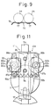
- FIGs 10 through 14 illustrate an embodiment in which the apparatus of the present invention is built midway in the passage for transporting roving bobbins to the respective positions above the spinning frames. Namely, in this embodiment, the operation of preventing unwinding of roving ends of roving bobbins is performed while the bobbin carriage 11 is continuously displaced. As shown in Figures 10 and 11 showing a continuous feeding device 49e in the midway of the transporting rail 7, the continuous feeding devices 49 are arranged at an intervened distance shorter than the total length of the bobbin carriage 11.
- a supporting bracket 86 is secured to the transporting rail 7
- a pair of supporting arms 87a and 87b are swingably pivoted on the supporting bracket 86 through vertical shafts 88a and 88b
- bearings 89a and 89b are secured to the intermediate parts of the supporting arms 87a and 87b.
- Roller shafts 90a and 90b are rotatably supported by the bearings 89a and 89b, and feed rollers 91a and 91b are secured to the lower end portions of the roller shafts 90a and 90b.
- the supporting arms 87a and 87b are urged inward by a spring 114 extended between the top end portions of the supporting arms 87a and 87b so that, if the bobbin carriage 11 is not present, the supporting arms 87a and 87b abut against stoppers 92a and 92b mounted on the supporting bracket 86.
- the feed rollers 91a and 91b are arranged so that when the bobbin carriage 11 is moved to the position of the feed rollers 91a and 91b, a carriage bar 11a of the bobbin carriage 11 is resiliently urged from both sides.
- a driving motor 93 is secured to one supporting arm 87a to rotate the rotor shaft 90a in one direction.
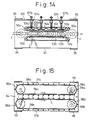
- a supporting body 94 is secured to the transporting rail 7 through an attachment arm 95 and is located below the passage for transporting roving bobbins 4.
- a pair of pulleys 96a and 96b are rotatably disposed to the supporting body 94 and are located on both sides of the lower end of the transporting passage. Two pairs of pulleys 96a and 96b are arranged with a certain distance therebetween in the transporting direction, and rotary belts 97a and 97b in contact with the lower end portion of each roving bobbin 4 are laid between pairs of pulleys 96a and 96b, respectively.
- positioning pieces 98a and 97b are arranged at predetermined pitches so that the positioning pieces 98a and 98b intrude between every two adjacent roving bobbins 4 carried in the suspended condition by the respective bobbin hangers 16 of the bobbin carriage 11, so that the suspended condition of the roving bobbins 4 can be maintained.
- the setting positions of the positioning pieces 98a and 98b are determined so that the positioning pieces 98a and 98b intrude before and after the lower end of each roving bobbin 4, respectively, and each roving bobbin 4 is transported in the condition in which it is positioned substantially vertically by the positioning pieces 98a and 98b.
- Driving motors 99a and 99b are disposed to rotate the rotary belts 97a and 97b in contact with the lower end portion of each roving bobbin 4 in the direction of the arrow at the same speed as the delivery speed of the bobbin carriage 11, and the driving motors 99a and 99b are secured to the supporting body 94 to rotate shafts of the pulleys 96a and 96b.
- a supporting plate 100 is secured to the attachment arm 95.
- a plurality of pairs, for example, 4 pairs in this embodiment, of upper and lower bearings 101a and 101b are arranged on the supporting plate 100 at intervals substantially equal to the pitches of the bobbin hangers 16.
- a pair of supporting frames 108a, 108b are secured to the transporting rail 7 and two pairs of bearings 109a and 109b are secured to the respective supporting frames 108a, 108b to rotatably support shafts of pulleys 110a and 110b.
- Driving motors 111a and 111b are secured to the respective supporting frames 108a, 108b to rotate the pulleys 110a, 110b in the direction of the arrow.
- Rotary belts 112a and 112b are laid between the respective pair of pulleys 110a and 110b and are rotated in the direction of the arrow.
- Belt guide plates 113a and 113b are secured to the transporting rail 7.
- the rotary belts 112a and 112b are arranged to press the top ends of the roving bobbins 4 from both sides in the suspended condition regulated by the device 74e and rotate the roving bobbins 4 in the roving-winding direction.
- the driving motor 93 of the continuous feeding device 49e (Fig. 10) is actuated to rotate the feed rollers 91a and 91b in the direction of the arrow, whereby the carriage bar 12 of the bobbin carriage 11 is continuously displaced in the transporting direction.
- the carriage bar 12 is resiliently urged from both sides by the feed rollers 90a and 90b of the subsequent feed device 49e, and the carriage bar 12 is thus displaced forwards successively.
- each roving bobbin 4 suspended by the respective bobbin hangers 16 intrudes into a position between the rotary belts 97a and 97b, which are preliminarily rotating and the position of the roving bobbin 4 is regulated by the positioning pieces 98a and 98b of the rotary belts 97a and 97b, whereby possible swinging of the roving bobbins 4 can be prevented.
- peripheral face of the winding portion 4a of each roving bobbin 4 abuts against the pressing plate 103 to deviate the pressing plate 103 sideways against the springs 105a and 105b and cause the pressing plate 103a to apply pressure to the peripheral face of the winding portion 4a of each roving bobbin 4.
- each roving bobbin 4 since the suspended condition of each roving bobbin 4 is maintained by the belts 97a, 97b and the peripheral face of each winding portion 4a of the roving bobbin 4 is pressed by the pressing plate 103a, when the roving bobbin 4 is rotated in the winding direction, the roving end is firmly attached on the peripheral face of the winding portion 4a of each roving bobbin 4.
- the preferable embodiments can be classified into two categories; i.e., the embodiments shown in the drawings from Fig. 1 to Fig. 6 and the embodiments shown in the drawings from Fig. 7 to Fig. 15.
- unwinding of the roving ends can be prevented during the transportation of the roving bobbins or during the subsequent steps, and therefore, the possible problem of the unwinding of the roving ends mentioned above can be prevented. Moreover, since unwinding of the roving ends is performed automatically while the roving bobbins are carried by the bobbin carriage, the time for transporting the roving bobbins can be effectively utilized.
Landscapes
- Engineering & Computer Science (AREA)
- Textile Engineering (AREA)
- Mechanical Engineering (AREA)
- Spinning Or Twisting Of Yarns (AREA)
- Replacing, Conveying, And Pick-Finding For Filamentary Materials (AREA)
Claims (8)
- Vorrichtung zum Verhindern des Abwickelns von Vorgarnenden enthaltend in Kombination eine Einrichtung zum Transportieren voller, von entsprechenden Spulenrädern eines Flyers (1) zu vorbestimmten Positionen gedofften Vorgarnspulen (4), wobei die Transporteinrichtung ausgestattet ist mit einer Vorrichtung (5, 6, 20, 60A) zum Verlagern der Vorgarnspulen (4), wobei die Vorrichtung ausgestattet ist mit einer Mehrzahl von Gliedern (16, 32, 64, 65) zum Tragen der Vorgarnspulen (4) in einer im wesentlichen vertikalen Lage, und ein Verlagerungsbauteil (11, 22, 62, 63), auf dem die Tragglieder (16, 32, 64, 65) drehbar montiert sind, und Mittel zum Verlagern des Verlagerungsbauteils (11, 22, 62, 63) längs einer vorbestimmten Bahn (17, 26), wobei die Vorgarnspulen (4) durch die Tragglieder (16, 32, 64, 65) während der Verlagerung des Verlagerungsbauteils (11, 22, 62, 63) getragen werden,
gekennzeichnet durch
ein Glied (34, 66, 74, 103) zum Anpressen einer Umfangsfläche eines Wickelbereichs jeder der Vorgarnspulen (4) und eine Mechanik (38, 79, 85, 93, 111a, 111b) zum Rotieren der Vorgarnspulen (4) in einer Wickelrichtung der Vorgarnspulen (4) unter Kontaktdruck des Anpreßglieds (34, 66, 74, 103), wobei das Anpreßglied (34, 66, 74, 103) an einer Position benachbart zu der vorbestimmten Bahn (7, 26) zum Transportieren der Vorgarnspulen (4) angeordnet ist. - Vorrichtung zum Verhindern des Abwickelns von Vorgarnenden entsprechend Anspruch 1,
wobei die Vorrichtung angewendet wird auf ein System zum Doffen voller Vorgarnspulen (4) von entsprechenden Spulenrädern eines Flyers mit Hilfe eines Doffers (3) und zum Transferieren der gedofften Vorgarnspulen zu entsprechenden Spulenhängevorrichtungen (16) eines Spulentransporters (11) eines Über-Kopf-Transportsystems (6) mit Hilfe einer Verlagerungsvorrichtung (20), wobei die Vorgarnspulen (4) von Positionen oberhalb des Flyers (1) zu entsprechenden Positionen oberhalb einer Spinnmaschine (2) längs eines Transportschienensystems (7), das zwischen den Positionen oberhalb des Flyers (1) und den Positionen oberhalb der Spinnmaschine (2) angeordnet ist, gebracht werden, wobei die Einrichtung zum Verhindern des Abwickelns der Vorgarnenden in Kombination mit Elementen der Verlagerungsvorrichtung (20) aufgebaut ist, worin jedes der Tragglieder einen Zapfen (32) zum Tragen einer vollen, von dem Flyer (1) mit Hilfe des Doffers (3) abgezogenen Vorgarnspule (4) aufweist, wobei das Bauteil einen Heber (27) zum Halten der Zapfen (32) umfaßt, wobei die Verlagerungsvorrichtung (20) eine Hebemechanik (22) zum Verlagern des Hebers (27) zwischen einer Position zum Empfangen der gedofften Vorgarnspulen von dem Doffer (3) und einer Position zum Transferieren der Vorgarnspulen (4) zu den jeweiligen Spulenhängevorrichtungen (16 ) umfaßt, und wobei die Rotiermechanik eine Vorrichtung (38) zum Rotieren der Zapfen (32) ist, wobei das Anpreßglied (34) und die Rotiervorrichtung (38) auf der Verlagerungsvorrichtung (20) montiert sind. - Anspruch zum Verhindern des Abwickelns von Vorgarnenden entsprechend Anspruch 2,
worin das Anpreßglied (34) umfaßt eine Blattfeder (35), die sich längs fast der ganzen Länge der Vorgarnspule (4) in einer axialen Richtung der Vorgarnspule (4) erstreckt, und ein Glied (36, 36a) zum Lösen der Anpreßwirkung der Blattfeder (35), wenn der Heber (27) an seiner untersten Position ist. - Vorrichtung zum Verhindern des Abwickelns von Vorgarnenden entsprechend Anspruch 2,
wobei die Vorrichtung in Kombination mit Elementen der an einer Position benachbart zu einem Ende einer Simultan-Doffer-Vorrichtung (3) angeordheten Verlagerungsvorrichtung aufgebaut ist, welcher Doffer (3) vor dem Flyer (1) angeordnet und mit einem Peg-Förderer (5) ausgestattet ist, der eine Mehrzahl von Zapfen (5a) zum Aufnehmen aller vollen, von den Spulenrädern des Flyers (1) gedofften Vorgarnspulen (4) besitzt, wobei die Verlagerungsvorrichtung (20) von den Zapfen (5a) des Peg-Förderers (5) empfangene Vorgarnspule (4) zu den jeweiligen Spulenhängevorrichtungen (16) des Spulenförderers (11) transferiert, welche Elemente des Über-Kopf-Transportsystems (6) sind. - Vorrichtung zum Verhindern des Abwickelns von Vorgarnenden entsprechend Anspruch 2,
wobei die Vorrichtung in Kombination mit Elementen der in einem bekannten Wagen-Typ-Doffer (60) gebildeten Verlagerungsvorrichtung (66A) konstruiert ist, welche sich längs des Flyers (1) in einer dem Flyer (1) zugewandten Lage so verlagern kann, daß der Doffer-Vorgang ausgeführt wird, wobei die Verlagerungsvorrichtung (66A) von den jeweiligen Spulenrädern des Flyers (1) empfangene Vorgarnspule (4) transferiert zu den entsprechenden Spulenhängevorrichtungen (16) der Spulentransporter (11), welche Elemente des Über-Kopf-Transportsystems (6) sind. - Vorrichtung zum Verhindern des Abwickelns von Vorgarnenden entsprechend Anspruch 1,
wobei die Vorrichtung in Kombination mit Elementen eines Über-Kopf-Transportsystems (6) zum Transportieren von Vorgarnspulen (4) von entsprechenden Positionen oberhalb des Flyers (1) zu entsprechenden Positionen oberhalb der Spinnmaschinen (2) längs einer zwischen den Positionen angeordneten Bahn (7) aufgebaut ist, wobei jedes der Transportglieder eine Spulerhängevorrichtung (16) umfaßt, wobei das Bauteil einen Spulentransporter (11) ausweist, auf dem die Spulenhängevorrichtungen (16) rotierbar montiert sind, und wobei das Verlagerungsmittel eine Antriebsmechanik (49) zum Verlagern des Spulentransporters (11) längs der Bahn (7) umfaßt, und wobei das Anpreßglied (75, 103) an einer Position in der Nähe der durch die Bahn (7) gebildeten Transportpassage für die Vorgarnspulen (4) angeordnet ist, wobei das Anpreßglied (75, 103) und die Mechanik (79, 112a, 112b) zum Rotieren der Vorgarnspulen (4) auf der Bahn (7) positioniert sind. - Vorrichtung zum Verhindern des Abwickelns von Vorgarnspulen entsprechend Anspruch 6,
wobei das Anpreßglied (75) mit Ausnehmungen (77) zum Aufnehmen eines Umfangsbereiches der Vorgarnspulen (4) ausgestattet ist, wobei das Anpreßglied (75) auf der Bahn (7) an einer Position angeordnet ist, wo die Antriebsmechanik (49) angehalten wird, während die Rotationsmechanik (79) eingeschaltet wird, um die Vorgarnspulen (4) unter Einwirkung des Kontaktdrucks des Anpreßglieds (75) zu rotieren. - Vorrichtung zum Verhindern des Abwickelns von Vorgarnspulen entsprechend Anspruch 6,
weiter umfassend Mittel zum Aufrechterhalten einer vertikal hängenden Lage der Vorgarnspulen (4) durch die Spulenhängevorrichtung (16), wenn das Anpreßglied (103) gegen die Umfangsflächen der Vorgarnspulen (4) drückt, während der Spulentransporter (11) längs der Bahn (7) verlagert wird, wobei die Mittel zum Aufrechterhalten der vertikal hängenden Lage der Vorgarnspulen (4) ein Paar erster endlos umlaufender Riemen (99a, 99b) umfaßt, von denen jeder mit einer Mehrzahl von Positionierteilen (98) versehen ist, die mit vorbestimmten Teilungen angeordnet sind, um eine Bedingung zu schaffen, in der die Positionerteile (98a, 98b) zwischen je zwei benachbarte, in hängender Lage an entsprechenden Spulenhängevorrichtungen (4) getragene Vorgarnspulen (4) dringen, wobei die Rotiermechanik ein Paar zweiter, endlos umlaufender Riemen (112a, 112b) umfaßt, welche die Vorgarnspulen (4) in deren Windungsrichtung in solcher Lage rotieren, daß ein oberes Endteil jeder der Vorgarnspulen (4) durch die endlosen Riemen (112a, 112b) von beiden Seiten gedrängt wird, während die Vorgarnspulen (4) transportiert werden, wobei das Anpreßglied (103) mit einem plattenartigen Andrückmittel (103a) ausgestattet ist, welches eine federnde Kraft zum Anpressen der Umfangsfläche des Wickelbereichs jeder Vorgarnspule (4) besitzt.
Applications Claiming Priority (4)
| Application Number | Priority Date | Filing Date | Title |
|---|---|---|---|
| JP122548/86 | 1986-05-28 | ||
| JP12254886A JPS62282029A (ja) | 1986-05-28 | 1986-05-28 | 粗糸搬送装置における粗糸端解舒防止装置 |
| JP145451/86 | 1986-06-21 | ||
| JP14545186A JPS636122A (ja) | 1986-06-21 | 1986-06-21 | 粗糸端解舒防止装置 |
Publications (3)
| Publication Number | Publication Date |
|---|---|
| EP0247973A2 EP0247973A2 (de) | 1987-12-02 |
| EP0247973A3 EP0247973A3 (de) | 1991-04-17 |
| EP0247973B1 true EP0247973B1 (de) | 1995-08-02 |
Family
ID=26459644
Family Applications (1)
| Application Number | Title | Priority Date | Filing Date |
|---|---|---|---|
| EP87810314A Expired - Lifetime EP0247973B1 (de) | 1986-05-28 | 1987-05-26 | Vorrichtung zur Verhinderung des Vorgarnendabwickelns, angewendet am Vorgarnspulentransportsystem |
Country Status (3)
| Country | Link |
|---|---|
| US (1) | US4769982A (de) |
| EP (1) | EP0247973B1 (de) |
| DE (1) | DE3751431T2 (de) |
Families Citing this family (14)
| Publication number | Priority date | Publication date | Assignee | Title |
|---|---|---|---|---|
| IT1222819B (it) * | 1987-10-02 | 1990-09-12 | Marzoli & C Spa | Apparecchiatura per banchi a fusi,atta ad effettuare,in modo automatico.il prelievo delle spole e la loro sostituzione con tubi vuoti,sui quali avvolgere lo stoppino |
| JP2554606B2 (ja) * | 1987-12-10 | 1996-11-13 | 豊和工業株式会社 | 粗糸ボビン搬送装置 |
| JPH03505760A (ja) | 1989-04-13 | 1991-12-12 | マシーネンファブリク リーター アクチェンゲゼルシャフト | パッケージ搬送システム |
| DE4023221A1 (de) * | 1990-07-21 | 1992-01-23 | Palitex Project Co Gmbh | Zwirnmaschine, insbesondere doppeldraht-zwirnmaschine |
| CH681813A5 (en) * | 1990-11-02 | 1993-05-28 | Rieter Ag Maschf | Slubbing end loose fixing at roving bobbin avoiding detachment in utilisation - by rotating bobbin in unwinding direction, freeing end from cylindrical section of wound roving, catching by suction, carrying to upper section and winding |
| JPH05148725A (ja) * | 1991-11-29 | 1993-06-15 | Towa Kogyo Kk | 紡機の粗糸自動搬送装置 |
| DE4401232A1 (de) * | 1994-01-18 | 1995-07-20 | Schlafhorst & Co W | Vereinzelungs- und Positioniervorrichtung |
| US20020043496A1 (en) * | 2000-08-01 | 2002-04-18 | Boddu Veera M. | Composite biosorbent for treatment of waste aqueous system(s) containing heavy metals |
| CN100587138C (zh) * | 2006-06-19 | 2010-02-03 | 东台纺织机械有限责任公司 | 细纱机管纱提升装置 |
| US7503270B2 (en) * | 2006-11-02 | 2009-03-17 | Irvin Automotive Products, Inc. | Bobbin system for use with a sewing machine |
| MX362619B (es) | 2012-11-12 | 2019-01-28 | Southwire Co Llc | Paquete de alambre y cable. |
| CN109082739B (zh) * | 2018-09-28 | 2024-06-14 | 陕西华燕航空仪表有限公司 | 一种筒管限位装置 |
| CN113026154B (zh) * | 2021-03-29 | 2022-11-11 | 魏桥纺织股份有限公司 | 一种粗纱机自触式防飘头装置 |
| CN117230551A (zh) * | 2023-10-26 | 2023-12-15 | 江苏赫伽力智能科技有限公司 | 一种基于环形轨道的一拖二上外丝系统 |
Family Cites Families (17)
| Publication number | Priority date | Publication date | Assignee | Title |
|---|---|---|---|---|
| GB191301903A (en) * | 1913-01-23 | 1914-01-23 | John Foster & Son Ltd | Improvements relating to Spinning and Analogous Machines. |
| DE525154C (de) * | 1927-12-31 | 1931-09-05 | Gertrud Buddecke Geb Lindner | Spulenauswechselvorrichtung, die an einem fahrbaren Kran haengend angebracht ist |
| DE1801978C3 (de) * | 1968-10-09 | 1974-04-11 | Schubert & Salzer Maschinenfabrik Ag, 8070 Ingolstadt | Verfahren und Vorrichtung zum selbsttätigen Aufbringen des Flyervorgarnes auf eine leere Hülse |
| GB1290671A (de) * | 1969-02-25 | 1972-09-27 | ||
| JPS5089642A (de) * | 1973-12-13 | 1975-07-18 | ||
| JPS5724414B2 (de) * | 1974-10-03 | 1982-05-24 | ||
| CH626663A5 (de) * | 1977-10-04 | 1981-11-30 | Rieter Ag Maschf | |
| JPS57106729A (en) * | 1980-11-20 | 1982-07-02 | Howa Mach Ltd | Method of exchanging bobbins in fly frame and device therefor |
| ES8203999A1 (es) * | 1981-03-10 | 1982-05-01 | Pons Ubach Antonia | Aparato automatico para la alimentacion de mecha en maquinascontinuas de hilar |
| CH662586A5 (de) * | 1982-03-20 | 1987-10-15 | Zinser Textilmaschinen Gmbh | Spinnanlage zur herstellung von garn aus vorgarn. |
| JPS5982433A (ja) * | 1982-11-02 | 1984-05-12 | Toyoda Autom Loom Works Ltd | 粗紡機における管替え方法及びその装置 |
| DE3240822A1 (de) * | 1982-11-05 | 1984-05-10 | Zinser Textilmaschinen Gmbh, 7333 Ebersbach | Ringspinnmaschine mit einem spulengatter |
| DE3312116A1 (de) * | 1983-04-02 | 1984-10-04 | Zinser Textilmaschinen Gmbh, 7333 Ebersbach | Vorrichtung zum ent- und beladen eines oberhalb einer ringspinnmaschine angeordneten spulengatters |
| US4473997A (en) * | 1983-04-29 | 1984-10-02 | Howa Kogyo Kabushiki Kaisha | Method and apparatus for switching roving bobbins in a spinning frame |
| JPS613896A (ja) * | 1984-06-15 | 1986-01-09 | Kosaku:Kk | 金色被膜形成用電気めつき浴 |
| JPS61174432A (ja) * | 1985-01-23 | 1986-08-06 | Howa Mach Ltd | 粗紡機の管替機 |
| DE3537396A1 (de) * | 1985-10-21 | 1987-04-23 | Zinser Textilmaschinen Gmbh | Verfahren und vorrichtung zum fixieren von fadenenden |
-
1987
- 1987-05-26 EP EP87810314A patent/EP0247973B1/de not_active Expired - Lifetime
- 1987-05-26 DE DE3751431T patent/DE3751431T2/de not_active Expired - Fee Related
- 1987-05-27 US US07/054,938 patent/US4769982A/en not_active Expired - Lifetime
Also Published As
| Publication number | Publication date |
|---|---|
| DE3751431D1 (de) | 1995-09-07 |
| EP0247973A3 (de) | 1991-04-17 |
| DE3751431T2 (de) | 1996-01-04 |
| EP0247973A2 (de) | 1987-12-02 |
| US4769982A (en) | 1988-09-13 |
Similar Documents
| Publication | Publication Date | Title |
|---|---|---|
| EP0247973B1 (de) | Vorrichtung zur Verhinderung des Vorgarnendabwickelns, angewendet am Vorgarnspulentransportsystem | |
| US4630435A (en) | System for automatically changing spools of a spinning machine | |
| EP0258188A2 (de) | Verfahren zum Verbinden von Vorgarnsträngen und zum Auswechseln von Vorgarnspulen in einer Ringspinnmaschine und Vorrichtung zur Durchführung dieses Verfahrens | |
| JP2554606B2 (ja) | 粗糸ボビン搬送装置 | |
| JPH0759460B2 (ja) | クリ−ルへのパッケ−ジ供給装置 | |
| US4987645A (en) | Automatic piecing of overlapped leading and trailing ends of slivers in a textile machine | |
| JPH0489768A (ja) | パッケージ搬送方法 | |
| JPH0364608B2 (de) | ||
| JPH07310245A (ja) | 粗糸ボビン搬送装置 | |
| JPH0362807B2 (de) | ||
| JP2694760B2 (ja) | 粗糸ボビンの粗糸端処理装置 | |
| JPH0377291B2 (de) | ||
| JPH0226944Y2 (de) | ||
| JP2531347Y2 (ja) | 粗糸搬送システム | |
| JP2973652B2 (ja) | 精紡機のロービングガイドへの粗糸掛け方法 | |
| JPH0653546B2 (ja) | 粗糸ボビンの搬送方法 | |
| JPH1121020A (ja) | 粗糸ボビン搬送方法及び粗糸ボビン搬送システム | |
| JPH0524250B2 (de) | ||
| JPH05278946A (ja) | 天井搬送車 | |
| JPS591733A (ja) | 精紡機の篠巻搬送マガジンへの篠巻ロ−デイング方法及びその装置 | |
| JPH0241184Y2 (de) | ||
| JPH055231A (ja) | 粗糸端解舒防止装置 | |
| JPH0342056Y2 (de) | ||
| JPS61289138A (ja) | 玉揚移載機 | |
| JPH07118954A (ja) | 二重撚糸機とパーンワインダとの連結システム |
Legal Events
| Date | Code | Title | Description |
|---|---|---|---|
| PUAI | Public reference made under article 153(3) epc to a published international application that has entered the european phase |
Free format text: ORIGINAL CODE: 0009012 |
|
| AK | Designated contracting states |
Kind code of ref document: A2 Designated state(s): CH DE IT LI |
|
| 17P | Request for examination filed |
Effective date: 19901219 |
|
| PUAL | Search report despatched |
Free format text: ORIGINAL CODE: 0009013 |
|
| AK | Designated contracting states |
Kind code of ref document: A3 Designated state(s): CH DE IT LI |
|
| RHK1 | Main classification (correction) |
Ipc: D01H 9/00 |
|
| 17Q | First examination report despatched |
Effective date: 19931007 |
|
| GRAA | (expected) grant |
Free format text: ORIGINAL CODE: 0009210 |
|
| AK | Designated contracting states |
Kind code of ref document: B1 Designated state(s): CH DE IT LI |
|
| ITF | It: translation for a ep patent filed | ||
| REF | Corresponds to: |
Ref document number: 3751431 Country of ref document: DE Date of ref document: 19950907 |
|
| PLBE | No opposition filed within time limit |
Free format text: ORIGINAL CODE: 0009261 |
|
| STAA | Information on the status of an ep patent application or granted ep patent |
Free format text: STATUS: NO OPPOSITION FILED WITHIN TIME LIMIT |
|
| 26N | No opposition filed | ||
| PGFP | Annual fee paid to national office [announced via postgrant information from national office to epo] |
Ref country code: DE Payment date: 20000531 Year of fee payment: 14 |
|
| PGFP | Annual fee paid to national office [announced via postgrant information from national office to epo] |
Ref country code: CH Payment date: 20010530 Year of fee payment: 15 |
|
| PG25 | Lapsed in a contracting state [announced via postgrant information from national office to epo] |
Ref country code: DE Free format text: LAPSE BECAUSE OF NON-PAYMENT OF DUE FEES Effective date: 20020301 |
|
| PG25 | Lapsed in a contracting state [announced via postgrant information from national office to epo] |
Ref country code: LI Free format text: LAPSE BECAUSE OF NON-PAYMENT OF DUE FEES Effective date: 20020531 Ref country code: CH Free format text: LAPSE BECAUSE OF NON-PAYMENT OF DUE FEES Effective date: 20020531 |
|
| REG | Reference to a national code |
Ref country code: CH Ref legal event code: PL |
|
| PG25 | Lapsed in a contracting state [announced via postgrant information from national office to epo] |
Ref country code: IT Free format text: LAPSE BECAUSE OF NON-PAYMENT OF DUE FEES Effective date: 20050526 |