EP0247973B1 - Apparatus for preventing unwinding of roving end applied to roving bobbin transporting system - Google Patents
Apparatus for preventing unwinding of roving end applied to roving bobbin transporting system Download PDFInfo
- Publication number
- EP0247973B1 EP0247973B1 EP87810314A EP87810314A EP0247973B1 EP 0247973 B1 EP0247973 B1 EP 0247973B1 EP 87810314 A EP87810314 A EP 87810314A EP 87810314 A EP87810314 A EP 87810314A EP 0247973 B1 EP0247973 B1 EP 0247973B1
- Authority
- EP
- European Patent Office
- Prior art keywords
- roving
- bobbin
- bobbins
- roving bobbins
- displacing
- Prior art date
- Legal status (The legal status is an assumption and is not a legal conclusion. Google has not performed a legal analysis and makes no representation as to the accuracy of the status listed.)
- Expired - Lifetime
Links
- 238000003825 pressing Methods 0.000 claims description 64
- 238000004804 winding Methods 0.000 claims description 47
- 230000007246 mechanism Effects 0.000 claims description 38
- 238000009987 spinning Methods 0.000 claims description 27
- 230000002093 peripheral effect Effects 0.000 claims description 25
- 239000011295 pitch Substances 0.000 claims description 16
- 230000009471 action Effects 0.000 claims description 5
- 238000006073 displacement reaction Methods 0.000 claims description 2
- 210000000078 claw Anatomy 0.000 description 6
- 230000001105 regulatory effect Effects 0.000 description 6
- 238000010276 construction Methods 0.000 description 5
- 230000000630 rising effect Effects 0.000 description 3
- 238000000034 method Methods 0.000 description 2
- 230000009467 reduction Effects 0.000 description 2
- 238000007665 sagging Methods 0.000 description 2
- 239000000835 fiber Substances 0.000 description 1
- 238000004519 manufacturing process Methods 0.000 description 1
- 230000032258 transport Effects 0.000 description 1
Images


Classifications
-
- D—TEXTILES; PAPER
- D01—NATURAL OR MAN-MADE THREADS OR FIBRES; SPINNING
- D01H—SPINNING OR TWISTING
- D01H9/00—Arrangements for replacing or removing bobbins, cores, receptacles, or completed packages at paying-out or take-up stations ; Combination of spinning-winding machine
- D01H9/18—Arrangements for replacing or removing bobbins, cores, receptacles, or completed packages at paying-out or take-up stations ; Combination of spinning-winding machine for supplying bobbins, cores, receptacles, or completed packages to, or transporting from, paying-out or take-up stations ; Arrangements to prevent unwinding of roving from roving bobbins
-
- B—PERFORMING OPERATIONS; TRANSPORTING
- B65—CONVEYING; PACKING; STORING; HANDLING THIN OR FILAMENTARY MATERIAL
- B65H—HANDLING THIN OR FILAMENTARY MATERIAL, e.g. SHEETS, WEBS, CABLES
- B65H65/00—Securing material to cores or formers
- B65H65/005—Securing end of yarn in the wound or completed package
-
- D—TEXTILES; PAPER
- D01—NATURAL OR MAN-MADE THREADS OR FIBRES; SPINNING
- D01H—SPINNING OR TWISTING
- D01H9/00—Arrangements for replacing or removing bobbins, cores, receptacles, or completed packages at paying-out or take-up stations ; Combination of spinning-winding machine
- D01H9/005—Arrangements for replacing or removing bobbins, cores, receptacles, or completed packages at paying-out or take-up stations ; Combination of spinning-winding machine for removing empty packages or cans and replacing by completed (full) packages or cans at paying-out stations; also combined with piecing of the roving
-
- B—PERFORMING OPERATIONS; TRANSPORTING
- B65—CONVEYING; PACKING; STORING; HANDLING THIN OR FILAMENTARY MATERIAL
- B65H—HANDLING THIN OR FILAMENTARY MATERIAL, e.g. SHEETS, WEBS, CABLES
- B65H2701/00—Handled material; Storage means
- B65H2701/30—Handled filamentary material
- B65H2701/31—Textiles threads or artificial strands of filaments
Definitions
- the present invention relates to an apparatus for preventing an unwinding of an end of a roving when roving bobbins doffed from a roving frame are transported to the vicinity of a creel of a spinning frame or the roving bobbins are mounted to the respective creels of the spinning frame.
- a roving bobbin transporting system As a means for transporting roving bobbins doffed from roving frames to spinning frames, a roving bobbin transporting system has been disclosed (JP-A-60 67368) in which a transporting rail system is arranged between the positions above the roving frames and the positions above the spinning frames, bobbin carriages are movably supported by the transporting rail system, roving bobbins doffed from the flyer frames are suspended from respective bobbin hangers of the bobbin carriages so that the roving bobbins are transported in this suspended condition to the respective positions above the spinning frames.
- a roving bobbin exchange apparatus has been developed so that roving bobbins are automatically exchanged with empty bobbins on the respective spinning creels.
- This apparatus has a function of firmly attaching a free end of a roving to the outer periphery of the winding portion of each roving bobbin, while the roving bobbins, doffed from the respective bobbin wheels of each roving frame, are displaced by a transporting means.
- the present invention relates to an apparatus having a function such that, while full roving bobbins doffed from the respective bobbin wheels of each roving frame are carried by the transporting means, each bobbin is rotated in the winding direction of the roving in a condition such that the peripheral face of the winding portion of each roving bobbin is under pressure by a certain pressing member, whereby the free end of the roving is firmly attached to the periphery of the winding portion of the roving bobbin.
- a transporting system in which the apparatus for preventing an unwinding of the roving end according to the present invention is built, includes various embodiments according to the system for transporting doffed roving bobbins to the spinning frames.
- This transporting system includes an embodiment in which a transporting apparatus having many bobbin hangers is moved along a transporting rail arranged between respective positions above the roving frames and respective positions above the spinning frames, while suspending doffed roving bobbins by respective bobbin hangers so that the doffed roving bobbins are transported from respective positions above roving frames to the respective positions above the spinning frames, and an embodiment in which full bobbins doffed from each roving frame are delivered to corresponding bobbin hangers of the above-mentioned transporting apparatus.
- the latter embodiment includes different modes adopted for the simultaneous doffing method and the method using a wagon type doffer, respectively.
- the transporting system including the apparatus of the present invention, comprises a moving body having supporting members for holding each roving bobbin in a condition such that each roving bobbin is substantially vertically supported, and means for displacing the moving body along a predetermined track, and in this transporting system, the roving bobbins taken out from the respective bobbin wheels of the roving frame are supported by the supporting member while being displaced to predetermined positions.
- the apparatus of the present invention comprises, in principle, a pressing member disposed in the vicinity of the predetermined track of this transporting system to apply pressure to the peripheral face of the winding portion of each roving bobbin and a mechanism for rotating the roving bobbin in the winding direction of a roving under the pressing action of the pressing member.
- the apparatus for preventing the unwinding of an end of a roving of each roving bobbin according to the present invention is characterized in that pressure is applied to the peripheral face of a roving bobbin by the pressing member, and the roving bobbin is rotated in the winding direction of the roving by the bobbin-rotating mechanism under the above mentioned pressure, whereby the roving end of the roving bobbin is pressed against the winding portion of the roving bobbin and firmly attached thereto, said pressing member being disposed at a position adjacent to said predetermined track for transporting said roving bobbins, and thus the above-mentioned problems are satisfactorily solved.
- a plurality of roving frames 1 and a plurality of spinning frames are arranged according to the production capacity of the mill.
- a simultaneous doffing apparatus 3 is disposed in front of each roving frame 1.
- This simultaneous doffing apparatus 3 is constructed so that all the roving bobbins 4 of each roving frame 1 are simultaneously doffed from the respective bobbin wheels of the roving frame and then mounted on a peg 5a of the peg conveyor 5 as shown in Fig. 2.
- the structure of this simultaneous doffing apparatus 3 is illustrated, for example, in Japanese Unexamined Patent Publication No. 57-106729, USP 4,369,621, GBP 2,089,379 or WGP 3,146,040.
- the specific structure of the simultaneous doffing apparatus is not particularly critical and, accordingly, an explanation thereof is omitted.
- An overhead roving bobbin transporting system 6 transports roving bobbins 4 doffed by the simultaneous doffing apparatus 3 to a corresponding spinning frame 2, and this transporting system 6 has the following construction. That is, a transporting rail 7 is arranged in a space between the roving frame-setting position 1A and the spinning frame-setting position 2A.
- the transporting rail 7 comprises branch rails 7b arranged along the respective roving frames 1 and spinning frames 2 and a main rail 7a connecting these branch rails 7b.
- the rails 7a and 7b are supported by brackets secured to the machine stands or ceiling.
- Each bobbin carriage 11 comprising a plurality of carrying members 10 is suspended on the transporting rail 7 so that each bobbin carriage 11 can move along the transporting rail 7.
- each carrying member 10 supporting levers 14 are secured to a carriage bar 12, and wheels (not shown) rotatably supported on both sides of a bearing portion (not shown) of the supporting lever 14 are placed on the supporting face of the transporting rail 7.
- bobbin hangers 16 are mounted at predetermined pitches P in the longitudinal direction of the carriage bar 12, and indexing pins 17 are secured to the upper face of the carriage bar 12 at pitches two times the attachment pitches P of the bobbin hangers 16, so that the indexing pins 17 expand from both edges of the carriage bar 12.
- a plurality of such carrying members 10 are connected by connecting bars 18 and connecting pins 19 so that the line of the carrying members 10 can be bent and the pitches between every two adjacent carrying members 10 are equal to the pitches P.
- the pitches P of the bobbin hangers 16 are adjusted to 2 times the spindle pitches in the spinning frame 2.
- a displacing device 20 for mounting the roving bobbins 4 doffed by the simultaneous doffing apparatus 3 to the respective bobbin hangers 16 of the bobbin carriage 11, comprises a bobbin transfer device 21 which is disposed in the vicinity of one end of the peg conveyor 5 so as to receive doffed roving bobbins 4 on the respective pegs 32 of a device 22 for lifting these received roving bobbins 4 to the respective bobbin hangers 16.
- the bobbin transfer device 21 comprises a pair of arms 23 mounted on a frame 21a of the device 21 in rotatable condition of predetermined angle and a plurality of holding claws 25 which are vertically movably supported on the top ends of the arms 23 which is actuated by a pneumatic cylinder 24 mounted on the device 21.
- These holding claws 25 can be opened and closed by a cylinder (not shown in the drawings).
- the top ends of the roving bobbins 4 supported by the pegs 5a of the peg conveyor 5 are held by these holding claws 25 and, thereafter, the roving bobbins 4 are taken from the pegs 5a, and the roving bobbins 4 are mounted on respective pegs 32, described below, of the lifting device 22.
- the roving end unwinding-preventing apparatus of the present invention is built in a part of mechanical elements constituting the lifting device 22, as shown in Figs. 3 and 4.
- a pair of vertical guide rails 26 are secured to left and right frames 22a.
- a lifter 27 is guided by the guiding rails 26, and the lifter 27 has a function of displacing roving bobbins upwards or downwards between two positions, that is a position for receiving doffed roving bobbins 4 by the respective pegs 32 and another position for transferring the above-mentioned roving bobbins 4 to the respective bobbin hangers 16 of the bobbin carriage 11.
- the pegs 32 function as members for supporting the respective roving bobbins
- the lifter 27 functions as a displacing body for displacing the respective supporting members, that is the pegs 32.
- a pair of guiding rollers 28 and a pair of regulating rollers 29 are rotatably attached to upper and lower parts of both the end portions of the lifter 27 through brackets.
- the guide rails 26 are held between the guiding rollers 28 and the regulating rollers 29 abut against the guiding rails 26 to maintain the posture of the lifter 27.
- This lifter 27 can be moved up and down by a predetermined distance by an appropriate lift mechanism operated by a pneumatic cylinder or motor, for example, a mechanism disclosed in Japanese Unexamined Patent Publication No. 58-41919.
- a pair of pegs 32 are rotatably mounted on the lifter 27 through bearings or the like in condition such that they project upwards, and when the lifter 27 is displaced to the uppermost position, the pegs 32 can be positioned to vertically confront two bobbin hangers 16 of the bobbin carriage 11 guided by the transporting rail 7.
- Each peg 32 is formed so that it can be inserted into the lower aperture of each roving bobbin 4 and each peg 32 has a receiving part 33 for receiving the lower face of the mounted roving bobbin 4.
- the pressing device and a part of the mechanism for revolving the pegs 32 are symmetrically disposed to the respective pegs 32 of the lifter 27, respectively.
- a pressing device 34 is mounted on the lifter 27 in a condition such that it is capable of pressing against the peripheral face of the roving bobbin 4 supported by the respective pegs 32.
- This pressing device 34 is provided with a plate spring 35 having a free end, and the base portion (lower portion) of the plate spring 35 is secured to the lifter 27 and a pressing portion 35a is formed on the top end of the plate spring 35 so that, in the natural state, the pressing portion 35a is capable of pressing against the peripheral face of the roving bobbin 4 mounted on the peg 32.
- an engaging piece 36 having a engaging aperture 36a extending in the vertical direction is integrally secured to the top end of the plate spring 35.
- a releasing pin 37 is secured to a frame 22a of the lifting device 22 as the engaging member, and the engaging pin 37 is formed in a tapered shape so that by the engagement of the releasing pin 37 with the engaging aperture 36a, the pressing portion 35a of the plate spring 35 is deformed to a withdrawn position separated from the peripheral face of the roving bobbin 4.
- the other engaging pin (not shown) is disposed at the upper position of the frame 22a of the lifting device and facing the releasing pin 37.
- This mechanism has a function such that, before the roving bobbins 4 are transferred to the respective bobbin hangers 16, the contact pressure of the plate spring 35 against the peripheral surface of the winding portion 4a of each roving bobbin 4 is eliminated.
- the engaging pin 37 may be a wedge piece or cam plate secured to the frame 22a, and in this case, an engaging piece is arranged on the plate spring 35 so that, when the lifter 27 is brought down, the engaging piece becomes engaged with the wedge piece or cam plate to displace the top end of the plate spring 35 outward.
- a bobbin-rotating mechanism 38 for revolving each peg 32 is secured to the frame of the lifter 27 for rotating the roving bobbin 4 mounted on the peg 32 in the winding direction of roving.
- This bobbin-rotating mechanism 38 is provided with a driving motor 39 secured to the lifter 27, and a pulley 40 is secured to a driving shaft 39a of the driving motor 39.
- a pulley 41 which works as an element of the bobbin-rotating mechanism 38, is formed integrally with the peg 32, and a belt 42 is led between this pulley 41 and the pulley 40.
- a dog (not shown) is integrally formed on the lifter 27 to actuate an upper limit switch (not shown) and a lower limit switch (not shown) at the falling and rising positions of the lifter 27, respectively.
- the driving motor 39 is arranged so that, when the lifter 27 rises and the dog separates from the lower limit switch, the driving motor 39 is rotated and driven, and when the dog actuates the upper limit switch, the driving motor 39 is stopped.
- a feeding device 49 intermittently displaces the bobbin carriage 11 for a predetermined distance along the transporting rail 7. Since the detailed mechanism and function of this device 49 are disclosed in the Japanese Examined Utility Model Application Showa 61-3896, the construction and function of this device are hereinafter only briefly explained.
- a main body 50 of this device is secured to the transporting rail 7, and a driving shaft (now shown) is rotatably mounted on the main body 50.
- a brake motor 54 is mounted on the main body 50, and this brake motor 54 is provided with a speed reduction mechanism.
- a chain 56 is laid on a chain wheel secured to an output shaft 55 of the brake motor 54 and a chain wheel (not shown) secured to the above-mentioned driving shaft, so that this driving shaft can be rotated in a predetermined direction.
- cranks are arranged in an almost horizontal condition respectively, and free end portions of these two cranks are connected to one of the cross-riders 58, respectively, which are supported on both sides of the main body 50 in a horizontal condition, respectively.
- the doffing machine 3 simultaneously doffs the roving bobbins 4 on the pegs 5a of the peg conveyor 5 from the roving frame 1. Then, the roving bobbins 4 on the peg conveyor 5 are displaced toward the bobbin-displacing device 20, and at the position where the first two roving bobbins 4 confront the holding claws 25 of the bobbin transfer device 21, the movement of the peg conveyor 5 is stopped.
- the holding claws 25 hold the top ends of the roving bobbins 4 and take the roving bobbins 4 from the pegs 5, and the claws 25 mount the roving bobbins 4 on the pegs 32 of the lifter 27 in the falling condition in the lifting device 22.
- the following action of the pressing device 34 is created for each peg 32, that is, the engaging aperture 36a of the engaging piece 36 in the pressing device 34 is engaged with the engaging pin 37 and the pressing portion 35a of the plate spring 35 is located outside the roving bobbin-present region on the lifter 27. Accordingly, the roving bobbins 4 can be easily mounted on the pegs 32 without coming in to contact with the pressing portions 35a (see Fig. 3).
- the driving motor 39 of the bobbin-rotating mechanism 38 is stopped in this condition and, therefore, the pegs 32 and the roving bobbins 4 mounted thereon are not rotated.
- the bobbin hangers 16 supported on the transporting rail 7 are moved to the positions confronting the pegs 32 on the lifter 27 and stopped at these positions. Then, the lifter 27 rises and the top ends of the roving bobbins 4 are transfered to the respective bobbin hangers 16 of the bobbin carriage 11.
- the driving motor 39 of the bobbin-rotating mechanism 38 is rotated and driven to rotate the belt 42 in the direction indicated by the arrow (Fig. 4) and rotate the pegs 32 and each roving bobbin 4 mounted thereon in the roving-winding direction.
- the pressing portion 35a of the plate spring 35 is in pressure contact with the peripheral face of the winding 4a of the roving bobbin 4 as mentioned above, the end of the roving is pressed against the winding 4a and firmly attached thereto by the rotation of each roving bobbin 4.
- the two roving bobbins 4 transfered to a pair of the bobbin hangers 16 are displaced forwards in the suspended condition.
- This intermittent movement is effected every time the roving bobbins 4 are transfered to the bobbin hangers 16, and when a predetermined number of roving bobbins 4 are mounted on all the bobbin hangers 16 of the bobbin carriage 11, the bobbin carriage 11 is carried to the respective positions above the spinning frames 2 by a continuous feed device 51 (see Fig. 1), as hereinafter explained.
- Figures 5 and 6 illustrate an embodiment in which the present invention is applied to the wagon type doffing machine disclosed in the specification of Japanese Patent Unexamined Publication No. 61-174432.
- a doffer 60 is arranged movably along the front face of the roving frame 1, and two pairs of peg bars 62 and 63 are mounted on a frame 61 of the doffer 60 so that the peg bars 62 and 63 can be moved in the vertical direction by an appropriate lift mechanism.
- the doffer 60 is provided with a mechanism 66A for transferring roving bobbins 4 received from the respective bobbin wheels of the roving frame 1 to the respective bobbin hangers 16 of the bobbin carriage 11.
- This bobbin transfer mechanism 60A is provided with a pair of peg bars 62, 63 whereon four or six pegs 64, 65, are mounted respectively, and these peg bars 62, 63 are capable of displacing in the vertical direction respectively in relation to the condition thereof by a lifting mechanism mounted on a machine frame 61 of the doffer 60.
- a doffing mechanism 70 is mounted on the frame 61 of the doffer 60 for doffing roving bobbins 4 of the roving frame 1 and mounting them on the respective pegs 64 of the peg bar 62 in the falling condition or taking out empty bobbins 4e mounted on pegs 65 of the peg bar 63 in the falling condition and mounting them on the respective bobbin wheels of the roving frame.
- the peg bar 62 is utilized as a constitutional element of the present invention as a moving body having supporting members for holding roving bobbins, while the peg 64 functions as the above-mentioned supporting member.
- the pegs 64 of the peg bar 62 are rotatably arranged as in the embodiment shown in Figs. 3 and 4 so that only while the peg bar 62 is in the rising condition are each of the pegs 64 revolved in the roving-winding direction of the roving bobbins 4 by a driving motor of a bobbin-rotating mechanism (not shown).
- a pressing member 66 is pivoted on the peg bar 62 at this base portion and the pressing member 66 is urged toward the axial line of the peg 64 by a spring 68 so that the pressing member 66 abuts against a stopper 67. Only while the peg bar 62 is in the falling condition and the rising condition, is the pressing member 66 released from the pressing action thereof by an action of a solenoid 69 as a releasing member, or a cam.
- the pressing surface 66a of the pressing member 66 comes into pressure contact with the peripheries of windings 4a of each roving bobbin 4 while the roving bobbin 4 is rotated in the roving-winding direction, whereby the roving ends can be firmly attached to the windings 4a of all roving bobbins 4.
- the apparatus exerts the intended function during the operation of transporting roving bobbins, where full roving bobbins doffed from the respective bobbin wheels of the roving frame are transported and transfered to the respective bobbin hangers of the bobbin carriage of the above-mentioned overhead type roving bobbin transporting system.
- An embodiment of the present invention applied to the overhead type roving bobbin transporting system, wherein the apparatus of the present invention functions in the time of carrying thee roving bobbins forwards along the transporting rail by displacing the bobbin carriage forwards, will now be described. In this embodiment, the explanation of the mechanism and function of the overhead type roving bobbin transporting system per se is omitted, to avoid duplication.
- FIG. 7 through 9 illustrate an embodiment where the roving end unwinding-preventing apparatus of the present invention is applied to the overhead type roving transporting apparatus shown in Fig. 2 wherein the profile of the apparatus of the present invention is shown by a one-dot chain line.
- a device for pressing the peripheral surface of the winding portion of roving bobbins is arranged in the midway of a passage for transporting roving bobbins 4 by the bobbin carriage 11.
- this device 74 is located at a second stop station in the transporting track from the position of the bobbin hanger 16 where the roving bobbins 4 are transferred by the bobbin-displacing device 20, however, preferably, the device 74 is located at a first stop position.
- a pressing plate 75 is secured to a bracket 71 fixed to the transporting rail 7 through an attachment screw 76, and the pressing plate 75 is located so that the lower end portion of the pressing plate 75 is exposed into the transporting passage for the roving bobbins 4 of the bobbin carriage 11, as shown in Fig. 9.
- a positioning recess 77 in which the peripheral face 4a of the winding portion of each roving bobbin 4 is fitted by its own weight in the state where the bobbin carriage 11 is intermittently stopped, whereby a swinging movement of the intermittently stopped roving bobbins 4 is prevented, so that the peripheral face of the winding portion 4a of the roving bobbin 4 can be subjected to a firm pressure.
- a bobbin-rotating mechanism 79 rotates each roving bobbin 4, regulating the suspended condition thereof by the member 75, in the roving-winding direction, and each roving bobbin 4 is rotated in the condition where the top end of the roving bobbin 4 is pressed from both sides.
- this bobbin-rotating mechanism 79 two pairs of bearings 80 and 81 are secured to the bracket 71, as shown in Fig. 7.
- the bearings 80 and 81 rotatably support shafts 82a and 83a of rotating rollers 82 and 83 respectively.
- a belt 84 is laid on the two shafts 83a on one side and one of these shafts 83a is rotated in one direction by a driving motor 85 secured to the bracket 71.
- the distance between the rotating rollers 82 and 83 is set so that the top end of each roving bobbin 4 regulating the suspended condition thereof is pressed from both sides thereof.
- one of the paired shafts 82a and 83a preferably the driven shaft 82a, may be supported so that the driven shaft 82a can approach to and separate from the driving shaft 83a, and each roving bobbin 4 may be resiliently pressed by the rotating rollers 82 and 83 when the shaft 82a is urged, toward the shaft 83a by a spring.
- One rotating roller 83 is intruded into a window 71a of the bracket 71.
- the roving bobbins 4 are simultaneously doffed on pegs 5a of the peg conveyor 5 from the roving frame 1 by the doffing machine 3, then the roving bobbins 4 on the peg conveyor 5 are transferred to the bobbin-displacing device 20 and mounted on the respective pegs 32 on the lifter 27, and the lifter 27 is displaced upward and the top ends of the roving bobbins 4 are caught by the respective bobbin hangers 16 of the bobbin carriage 11.
- this downward displacement is detected by an appropriate detecting means and the brake motor 54 of the intermittent feed device 49 of the foregoing embodiment (Fig.
- the roving bobbins 4 mounted on the respective bobbin hangers 16 are displaced in the suspended condition.
- the intermediate parts of the roving bobbins 4 are guided by the guide portion of the pressing plate 75 and each winding portion 4a of the roving bobbin 4 is fitted in one of the positioning recesses 77 by the weight of the roving bobbins 4 themselves, and as a result, the peripheral faces of the winding portion 4a of each roving bobbin 4 is pressed against the inner face of the respective positioning recesses 77 of the pressing plate 75 by the weight of the roving bobbins 4 themselves.
- the rotating rollers 82 and 83 are rotated for a predetermined time by the driving motor 85, and as a result, the rotating rollers 82 and 83 rotate the roving bobbins 4 in the winding direction thereof.
- the above-mentioned intermittent movement of the bobbin carriage 11 is effected every time the roving bobbins 4 are mounted on the respective bobbin hangers 16.
- the bobbin carriage 11 is moved to the respective positions above the spinning frame 2 by a continuous feeding device, which will be explained hereinafter.
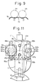
- FIGs 10 through 14 illustrate an embodiment in which the apparatus of the present invention is built midway in the passage for transporting roving bobbins to the respective positions above the spinning frames. Namely, in this embodiment, the operation of preventing unwinding of roving ends of roving bobbins is performed while the bobbin carriage 11 is continuously displaced. As shown in Figures 10 and 11 showing a continuous feeding device 49e in the midway of the transporting rail 7, the continuous feeding devices 49 are arranged at an intervened distance shorter than the total length of the bobbin carriage 11.
- a supporting bracket 86 is secured to the transporting rail 7
- a pair of supporting arms 87a and 87b are swingably pivoted on the supporting bracket 86 through vertical shafts 88a and 88b
- bearings 89a and 89b are secured to the intermediate parts of the supporting arms 87a and 87b.
- Roller shafts 90a and 90b are rotatably supported by the bearings 89a and 89b, and feed rollers 91a and 91b are secured to the lower end portions of the roller shafts 90a and 90b.
- the supporting arms 87a and 87b are urged inward by a spring 114 extended between the top end portions of the supporting arms 87a and 87b so that, if the bobbin carriage 11 is not present, the supporting arms 87a and 87b abut against stoppers 92a and 92b mounted on the supporting bracket 86.
- the feed rollers 91a and 91b are arranged so that when the bobbin carriage 11 is moved to the position of the feed rollers 91a and 91b, a carriage bar 11a of the bobbin carriage 11 is resiliently urged from both sides.
- a driving motor 93 is secured to one supporting arm 87a to rotate the rotor shaft 90a in one direction.
- a supporting body 94 is secured to the transporting rail 7 through an attachment arm 95 and is located below the passage for transporting roving bobbins 4.
- a pair of pulleys 96a and 96b are rotatably disposed to the supporting body 94 and are located on both sides of the lower end of the transporting passage. Two pairs of pulleys 96a and 96b are arranged with a certain distance therebetween in the transporting direction, and rotary belts 97a and 97b in contact with the lower end portion of each roving bobbin 4 are laid between pairs of pulleys 96a and 96b, respectively.
- positioning pieces 98a and 97b are arranged at predetermined pitches so that the positioning pieces 98a and 98b intrude between every two adjacent roving bobbins 4 carried in the suspended condition by the respective bobbin hangers 16 of the bobbin carriage 11, so that the suspended condition of the roving bobbins 4 can be maintained.
- the setting positions of the positioning pieces 98a and 98b are determined so that the positioning pieces 98a and 98b intrude before and after the lower end of each roving bobbin 4, respectively, and each roving bobbin 4 is transported in the condition in which it is positioned substantially vertically by the positioning pieces 98a and 98b.
- Driving motors 99a and 99b are disposed to rotate the rotary belts 97a and 97b in contact with the lower end portion of each roving bobbin 4 in the direction of the arrow at the same speed as the delivery speed of the bobbin carriage 11, and the driving motors 99a and 99b are secured to the supporting body 94 to rotate shafts of the pulleys 96a and 96b.
- a supporting plate 100 is secured to the attachment arm 95.
- a plurality of pairs, for example, 4 pairs in this embodiment, of upper and lower bearings 101a and 101b are arranged on the supporting plate 100 at intervals substantially equal to the pitches of the bobbin hangers 16.
- a pair of supporting frames 108a, 108b are secured to the transporting rail 7 and two pairs of bearings 109a and 109b are secured to the respective supporting frames 108a, 108b to rotatably support shafts of pulleys 110a and 110b.
- Driving motors 111a and 111b are secured to the respective supporting frames 108a, 108b to rotate the pulleys 110a, 110b in the direction of the arrow.
- Rotary belts 112a and 112b are laid between the respective pair of pulleys 110a and 110b and are rotated in the direction of the arrow.
- Belt guide plates 113a and 113b are secured to the transporting rail 7.
- the rotary belts 112a and 112b are arranged to press the top ends of the roving bobbins 4 from both sides in the suspended condition regulated by the device 74e and rotate the roving bobbins 4 in the roving-winding direction.
- the driving motor 93 of the continuous feeding device 49e (Fig. 10) is actuated to rotate the feed rollers 91a and 91b in the direction of the arrow, whereby the carriage bar 12 of the bobbin carriage 11 is continuously displaced in the transporting direction.
- the carriage bar 12 is resiliently urged from both sides by the feed rollers 90a and 90b of the subsequent feed device 49e, and the carriage bar 12 is thus displaced forwards successively.
- each roving bobbin 4 suspended by the respective bobbin hangers 16 intrudes into a position between the rotary belts 97a and 97b, which are preliminarily rotating and the position of the roving bobbin 4 is regulated by the positioning pieces 98a and 98b of the rotary belts 97a and 97b, whereby possible swinging of the roving bobbins 4 can be prevented.
- peripheral face of the winding portion 4a of each roving bobbin 4 abuts against the pressing plate 103 to deviate the pressing plate 103 sideways against the springs 105a and 105b and cause the pressing plate 103a to apply pressure to the peripheral face of the winding portion 4a of each roving bobbin 4.
- each roving bobbin 4 since the suspended condition of each roving bobbin 4 is maintained by the belts 97a, 97b and the peripheral face of each winding portion 4a of the roving bobbin 4 is pressed by the pressing plate 103a, when the roving bobbin 4 is rotated in the winding direction, the roving end is firmly attached on the peripheral face of the winding portion 4a of each roving bobbin 4.
- the preferable embodiments can be classified into two categories; i.e., the embodiments shown in the drawings from Fig. 1 to Fig. 6 and the embodiments shown in the drawings from Fig. 7 to Fig. 15.
- unwinding of the roving ends can be prevented during the transportation of the roving bobbins or during the subsequent steps, and therefore, the possible problem of the unwinding of the roving ends mentioned above can be prevented. Moreover, since unwinding of the roving ends is performed automatically while the roving bobbins are carried by the bobbin carriage, the time for transporting the roving bobbins can be effectively utilized.
Landscapes
- Engineering & Computer Science (AREA)
- Textile Engineering (AREA)
- Mechanical Engineering (AREA)
- Spinning Or Twisting Of Yarns (AREA)
- Replacing, Conveying, And Pick-Finding For Filamentary Materials (AREA)
Description
- The present invention relates to an apparatus for preventing an unwinding of an end of a roving when roving bobbins doffed from a roving frame are transported to the vicinity of a creel of a spinning frame or the roving bobbins are mounted to the respective creels of the spinning frame.
- As a means for transporting roving bobbins doffed from roving frames to spinning frames, a roving bobbin transporting system has been disclosed (JP-A-60 67368) in which a transporting rail system is arranged between the positions above the roving frames and the positions above the spinning frames, bobbin carriages are movably supported by the transporting rail system, roving bobbins doffed from the flyer frames are suspended from respective bobbin hangers of the bobbin carriages so that the roving bobbins are transported in this suspended condition to the respective positions above the spinning frames. Furthermore, as means for mounting roving bobbins transported to the respective positions above the spinning frames to the respective spinning creels, a roving bobbin exchange apparatus has been developed so that roving bobbins are automatically exchanged with empty bobbins on the respective spinning creels.
- When roving bobbins are transported by the above-mentioned roving transporting system or roving bobbins are mounted on the respective spinning creels by the bobbin exchange apparatus, the following problem has arisen. Namely, since the roving end of a roving bobbin doffed from the roving frame is not sufficiently attached to the winding portion of the roving bobbin, the roving end separates from the winding portion of the roving bobbin and sags down during the transportation of the roving bobbins, or during the roving bobbin exchange operation in the spinning frame. This sagging occurs frequently in the case of a combed yarn, and the weight of the roving in the sagging portion causes the roving on the roving bobbin to be gradually unwound, and the unwound roving of the roving bobbin is scattered and causes various problems.
- It is an object of the present invention to provide an apparatus for preventing an unwinding of a roving end in a roving bobbin, which can solve the above-mentioned problem. This apparatus has a function of firmly attaching a free end of a roving to the outer periphery of the winding portion of each roving bobbin, while the roving bobbins, doffed from the respective bobbin wheels of each roving frame, are displaced by a transporting means. More specifically, the present invention relates to an apparatus having a function such that, while full roving bobbins doffed from the respective bobbin wheels of each roving frame are carried by the transporting means, each bobbin is rotated in the winding direction of the roving in a condition such that the peripheral face of the winding portion of each roving bobbin is under pressure by a certain pressing member, whereby the free end of the roving is firmly attached to the periphery of the winding portion of the roving bobbin.
- A transporting system, in which the apparatus for preventing an unwinding of the roving end according to the present invention is built, includes various embodiments according to the system for transporting doffed roving bobbins to the spinning frames. This transporting system includes an embodiment in which a transporting apparatus having many bobbin hangers is moved along a transporting rail arranged between respective positions above the roving frames and respective positions above the spinning frames, while suspending doffed roving bobbins by respective bobbin hangers so that the doffed roving bobbins are transported from respective positions above roving frames to the respective positions above the spinning frames, and an embodiment in which full bobbins doffed from each roving frame are delivered to corresponding bobbin hangers of the above-mentioned transporting apparatus. The latter embodiment includes different modes adopted for the simultaneous doffing method and the method using a wagon type doffer, respectively.
- In each case, the transporting system, including the apparatus of the present invention, comprises a moving body having supporting members for holding each roving bobbin in a condition such that each roving bobbin is substantially vertically supported, and means for displacing the moving body along a predetermined track, and in this transporting system, the roving bobbins taken out from the respective bobbin wheels of the roving frame are supported by the supporting member while being displaced to predetermined positions. The apparatus of the present invention comprises, in principle, a pressing member disposed in the vicinity of the predetermined track of this transporting system to apply pressure to the peripheral face of the winding portion of each roving bobbin and a mechanism for rotating the roving bobbin in the winding direction of a roving under the pressing action of the pressing member.
- As is apparent from the above-mentioned basic construction of the apparatus of the present invention, irrespective of the embodiments, the apparatus for preventing the unwinding of an end of a roving of each roving bobbin according to the present invention is characterized in that pressure is applied to the peripheral face of a roving bobbin by the pressing member, and the roving bobbin is rotated in the winding direction of the roving by the bobbin-rotating mechanism under the above mentioned pressure, whereby the roving end of the roving bobbin is pressed against the winding portion of the roving bobbin and firmly attached thereto, said pressing member being disposed at a position adjacent to said predetermined track for transporting said roving bobbins, and thus the above-mentioned problems are satisfactorily solved.
-
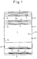
- Figure 1 is a plane view illustrating the layout of a roving bobbin transporting system (simultaneous doffing system) arranged between the respective positions above roving frames and the respective positions of spinning frames;
- Fig. 2 is a partial front view of the roving bobbin transporting system shown in Fig. 1, in relation to a full bobbin mounting apparatus wherein the apparatus of the present invention is applied, which is disposed at a position adjacent to one end of a peg conveyor constituting a part of the simultaneous doffing apparatus;
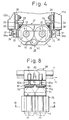
- Fig. 3 is a front view of the roving end unwinding-preventing apparatus of the present invention which is combined with a part of mechanical elements constituting a roving bobbin lifting mechanism which is a part of the full bobbin-mounting apparatus shown in Fig. 2;
- Fig. 4 is a plane view showing a main part of the roving end unwinding-preventing apparatus shown in Fig. 3;
- Fig. 5 is a schematic side view of an embodiment in which the roving end unwinding-preventing apparatus of the present invention is combined with a part of mechanical elements constituting a wagon type doffing apparatus, in which a system is adopted for transfering a full roving bobbin doffed by this doffing apparatus to corresponding bobbin hangers of a bobbin carriage of a transporting apparatus of the overhead roving bobbin transporting system shown in Fig. 1;
- Fig. 6 is a partial side view of the apparatus of the present invention shown in Fig. 5;
- Fig. 7 is a partial side view of the roving end unwinding-preventing apparatus according to the present invention, which is built in the bobbin transporting rail along which bobbin carriages of the roving bobbin transporting system shown in Fig. 1 can be displaced;
- Fig. 8 is a partial front view of an embodiment in which the roving end unwinding-preventing apparatus shown in Fig. 7 is built in the transporting apparatus (the profile is shown by the dotted line) located at the position VIII (indicated by the arrow) of the transporting system shown in Fig. 2;
- Fig. 9 is a sectional view showing the section taken along the line IX-IX in Fig. 8;
- Fig. 10 is a partial sectional side view (seen from the carrying direction along the transporting rail) showing another embodiment of the transporting apparatus used in the roving bobbin transporting system shown in Fig. 1, in which the roving end unwinding-preventing apparatus of the present invention is built;
- Fig. 11 is a plane view of the transporting apparatus shown in Fig. 10;
- Fig. 12 is a partial sectional side view (seen from the carrying direction of the transporting system) illustrating another embodiment of the roving end unwinding-preventing apparatus of the present invention which is built in the roving bobbin transporting system shown in Fig. 1;
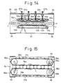
- Fig. 13 is a partial front view of the apparatus shown in Fig. 12;
- Fig. 14 is a view showing the section taken along the line XIV-XIV in the apparatus shown in Fig. 12; and,
- Fig. 15 is a view showing the section taken along the line XV-XV in the apparatus shown in Fig. 12.
- The construction and function of an embodiment in which the roving end unwinding-preventing apparatus of the present invention is applied to an apparatus for mounting roving bobbins doffed from a roving frame to corresponding bobbin hangers of a bobbin carriage of a roving bobbin transporting apparatus of the overhead bobbin transporting system will now be described with reference to Figs. 1 through 4.
- In Fig. 1, a plurality of
roving frames 1 and a plurality of spinning frames are arranged according to the production capacity of the mill. Asimultaneous doffing apparatus 3 is disposed in front of each rovingframe 1. Thissimultaneous doffing apparatus 3 is constructed so that all theroving bobbins 4 of each rovingframe 1 are simultaneously doffed from the respective bobbin wheels of the roving frame and then mounted on apeg 5a of thepeg conveyor 5 as shown in Fig. 2. The structure of thissimultaneous doffing apparatus 3 is illustrated, for example, in Japanese Unexamined Patent Publication No. 57-106729, USP 4,369,621, GBP 2,089,379 or WGP 3,146,040. In the present invention, the specific structure of the simultaneous doffing apparatus is not particularly critical and, accordingly, an explanation thereof is omitted. - An overhead roving
bobbin transporting system 6 transports rovingbobbins 4 doffed by thesimultaneous doffing apparatus 3 to acorresponding spinning frame 2, and thistransporting system 6 has the following construction. That is, a transportingrail 7 is arranged in a space between the roving frame-setting position 1A and the spinning frame-setting position 2A. The transportingrail 7 comprisesbranch rails 7b arranged along therespective roving frames 1 andspinning frames 2 and amain rail 7a connecting thesebranch rails 7b. Therails bobbin carriage 11 comprising a plurality of carryingmembers 10 is suspended on the transportingrail 7 so that eachbobbin carriage 11 can move along the transportingrail 7. As shown in Fig. 2, in each carryingmember 10, supportinglevers 14 are secured to acarriage bar 12, and wheels (not shown) rotatably supported on both sides of a bearing portion (not shown) of the supportinglever 14 are placed on the supporting face of the transportingrail 7. On the lower face of thecarriage bar 12,bobbin hangers 16 are mounted at predetermined pitches P in the longitudinal direction of thecarriage bar 12, and indexingpins 17 are secured to the upper face of thecarriage bar 12 at pitches two times the attachment pitches P of thebobbin hangers 16, so that the indexingpins 17 expand from both edges of thecarriage bar 12. - A plurality of such carrying
members 10 are connected by connectingbars 18 and connectingpins 19 so that the line of the carryingmembers 10 can be bent and the pitches between every two adjacent carryingmembers 10 are equal to the pitches P. In general, the pitches P of thebobbin hangers 16 are adjusted to 2 times the spindle pitches in the spinningframe 2. - A
displacing device 20 for mounting the rovingbobbins 4 doffed by thesimultaneous doffing apparatus 3 to therespective bobbin hangers 16 of thebobbin carriage 11, comprises abobbin transfer device 21 which is disposed in the vicinity of one end of thepeg conveyor 5 so as to receive doffed rovingbobbins 4 on therespective pegs 32 of a device 22 for lifting these received rovingbobbins 4 to therespective bobbin hangers 16. Thebobbin transfer device 21 comprises a pair ofarms 23 mounted on aframe 21a of thedevice 21 in rotatable condition of predetermined angle and a plurality ofholding claws 25 which are vertically movably supported on the top ends of thearms 23 which is actuated by apneumatic cylinder 24 mounted on thedevice 21. Theseholding claws 25 can be opened and closed by a cylinder (not shown in the drawings). The top ends of the rovingbobbins 4 supported by thepegs 5a of thepeg conveyor 5 are held by theseholding claws 25 and, thereafter, theroving bobbins 4 are taken from thepegs 5a, and theroving bobbins 4 are mounted onrespective pegs 32, described below, of the lifting device 22. - The roving end unwinding-preventing apparatus of the present invention is built in a part of mechanical elements constituting the lifting device 22, as shown in Figs. 3 and 4.
- In the lifting device 22, a pair of
vertical guide rails 26 are secured to left andright frames 22a. Alifter 27 is guided by the guidingrails 26, and thelifter 27 has a function of displacing roving bobbins upwards or downwards between two positions, that is a position for receiving doffed rovingbobbins 4 by therespective pegs 32 and another position for transferring the above-mentionedroving bobbins 4 to therespective bobbin hangers 16 of thebobbin carriage 11. In this embodiment, thepegs 32 function as members for supporting the respective roving bobbins, while thelifter 27 functions as a displacing body for displacing the respective supporting members, that is thepegs 32. A pair of guidingrollers 28 and a pair of regulatingrollers 29 are rotatably attached to upper and lower parts of both the end portions of thelifter 27 through brackets. Theguide rails 26 are held between the guidingrollers 28 and the regulatingrollers 29 abut against the guidingrails 26 to maintain the posture of thelifter 27. Thislifter 27 can be moved up and down by a predetermined distance by an appropriate lift mechanism operated by a pneumatic cylinder or motor, for example, a mechanism disclosed in Japanese Unexamined Patent Publication No. 58-41919. A pair ofpegs 32 are rotatably mounted on thelifter 27 through bearings or the like in condition such that they project upwards, and when thelifter 27 is displaced to the uppermost position, thepegs 32 can be positioned to vertically confront twobobbin hangers 16 of thebobbin carriage 11 guided by the transportingrail 7. Eachpeg 32 is formed so that it can be inserted into the lower aperture of eachroving bobbin 4 and eachpeg 32 has a receivingpart 33 for receiving the lower face of the mountedroving bobbin 4. In this embodiment, the pressing device and a part of the mechanism for revolving thepegs 32 are symmetrically disposed to therespective pegs 32 of thelifter 27, respectively. The construction and function of these machine elements related to one of thesepegs 32 are hereinafter explained. Apressing device 34 is mounted on thelifter 27 in a condition such that it is capable of pressing against the peripheral face of theroving bobbin 4 supported by the respective pegs 32. Thispressing device 34 is provided with aplate spring 35 having a free end, and the base portion (lower portion) of theplate spring 35 is secured to thelifter 27 and apressing portion 35a is formed on the top end of theplate spring 35 so that, in the natural state, thepressing portion 35a is capable of pressing against the peripheral face of theroving bobbin 4 mounted on thepeg 32. As shown in Fig. 4, an engagingpiece 36 having a engagingaperture 36a extending in the vertical direction is integrally secured to the top end of theplate spring 35. A releasingpin 37 is secured to aframe 22a of the lifting device 22 as the engaging member, and the engagingpin 37 is formed in a tapered shape so that by the engagement of the releasingpin 37 with the engagingaperture 36a, thepressing portion 35a of theplate spring 35 is deformed to a withdrawn position separated from the peripheral face of theroving bobbin 4. - Note, the other engaging pin (not shown) is disposed at the upper position of the
frame 22a of the lifting device and facing the releasingpin 37. This mechanism has a function such that, before theroving bobbins 4 are transferred to therespective bobbin hangers 16, the contact pressure of theplate spring 35 against the peripheral surface of the windingportion 4a of eachroving bobbin 4 is eliminated. The engagingpin 37 may be a wedge piece or cam plate secured to theframe 22a, and in this case, an engaging piece is arranged on theplate spring 35 so that, when thelifter 27 is brought down, the engaging piece becomes engaged with the wedge piece or cam plate to displace the top end of theplate spring 35 outward. A bobbin-rotatingmechanism 38 for revolving eachpeg 32 is secured to the frame of thelifter 27 for rotating theroving bobbin 4 mounted on thepeg 32 in the winding direction of roving. This bobbin-rotatingmechanism 38, is provided with a drivingmotor 39 secured to thelifter 27, and apulley 40 is secured to a drivingshaft 39a of the drivingmotor 39. Apulley 41, which works as an element of the bobbin-rotatingmechanism 38, is formed integrally with thepeg 32, and abelt 42 is led between thispulley 41 and thepulley 40. A dog (not shown) is integrally formed on thelifter 27 to actuate an upper limit switch (not shown) and a lower limit switch (not shown) at the falling and rising positions of thelifter 27, respectively. The drivingmotor 39 is arranged so that, when thelifter 27 rises and the dog separates from the lower limit switch, the drivingmotor 39 is rotated and driven, and when the dog actuates the upper limit switch, the drivingmotor 39 is stopped. - A
feeding device 49 intermittently displaces thebobbin carriage 11 for a predetermined distance along the transportingrail 7. Since the detailed mechanism and function of thisdevice 49 are disclosed in the Japanese Examined Utility Model Application Showa 61-3896, the construction and function of this device are hereinafter only briefly explained. In Fig. 2, amain body 50 of this device is secured to the transportingrail 7, and a driving shaft (now shown) is rotatably mounted on themain body 50. Abrake motor 54 is mounted on themain body 50, and thisbrake motor 54 is provided with a speed reduction mechanism. Achain 56 is laid on a chain wheel secured to anoutput shaft 55 of thebrake motor 54 and a chain wheel (not shown) secured to the above-mentioned driving shaft, so that this driving shaft can be rotated in a predetermined direction. A pair of cranks (not shown), which are respectively secured to both end portions of the above-mentioned driving shaft in a particular condition such that the angular phase difference with regard to the axial center of the driving shaft between these two cranks is 180°. These cranks are arranged in an almost horizontal condition respectively, and free end portions of these two cranks are connected to one of the cross-riders 58, respectively, which are supported on both sides of themain body 50 in a horizontal condition, respectively. In the above-mentioned mechanism, when the cranks have made a half turn, these twocross-riders 58 are displaced in opposite directions by a stroke which is twice the arrangement pitch P of thebobbin hangers 16, respectively. A mechanism for alternate engagement with and disengagement from theindexing pin 17 of thebobbin carriage 11 is mounted on thesecross-riders 58 respectively, so that, when either one of thesecross-riders 58 is displaced to a position wherein the free end portion thereof is in a backward end position (in Fig. 2). This mechanism engages with theindexing pin 17, while when either one of thesecross-riders 58 is displaced to a position where free end portion thereof is in a forward end position (in Fig. 2), this mechanism disengages from theindexing pin 17. Therefore, according to the rotation of thebrake motor 54, when the driving shaft is rotated by a half turn either one of the cross-riders 58 which is in the backward end position (in Fig. 2), comes to the most backward side, this cross-rider 58 engages with theindexing pin 17, and therefore, thebobbin carriage 11 can be displaced forward by a stroke which is twice that of the arrangement pitch P of thebobbin hangers 16, according to successive half turn rotations of the driving shaft. - In the above-mentioned embodiment, when
roving bobbins 4 formed by theroving frame 1 are carried to the respective positions above spinningframes 2, the doffingmachine 3 simultaneously doffs theroving bobbins 4 on thepegs 5a of thepeg conveyor 5 from theroving frame 1. Then, theroving bobbins 4 on thepeg conveyor 5 are displaced toward the bobbin-displacingdevice 20, and at the position where the first tworoving bobbins 4 confront the holdingclaws 25 of thebobbin transfer device 21, the movement of thepeg conveyor 5 is stopped. Then, the holdingclaws 25 hold the top ends of theroving bobbins 4 and take theroving bobbins 4 from thepegs 5, and theclaws 25 mount theroving bobbins 4 on thepegs 32 of thelifter 27 in the falling condition in the lifting device 22. In this condition, the following action of thepressing device 34 is created for eachpeg 32, that is, the engagingaperture 36a of the engagingpiece 36 in thepressing device 34 is engaged with the engagingpin 37 and thepressing portion 35a of theplate spring 35 is located outside the roving bobbin-present region on thelifter 27. Accordingly, theroving bobbins 4 can be easily mounted on thepegs 32 without coming in to contact with thepressing portions 35a (see Fig. 3). The drivingmotor 39 of the bobbin-rotatingmechanism 38 is stopped in this condition and, therefore, thepegs 32 and theroving bobbins 4 mounted thereon are not rotated. On the other hand, thebobbin hangers 16 supported on the transportingrail 7 are moved to the positions confronting thepegs 32 on thelifter 27 and stopped at these positions. Then, thelifter 27 rises and the top ends of theroving bobbins 4 are transfered to therespective bobbin hangers 16 of thebobbin carriage 11. In the above-mentioned case, when thelifter 27 rises slightly from the lowermost position, regarding eachpeg 32, the engagingaperture 36a of the engagingpiece 36 separates from the engagingpin 37, and as a result, thepressing portion 35a of theplate spring 35 is deformed inward (to the position indicated by a dot-line in Fig. 3) by the resilient force of theplate spring 35 per se, and thepressing portion 35a comes in to pressing contact with the peripheral faces of winding 4a of eachroving bobbin 4 mounted on the respective pegs 32 (at the position indicated by the solid line in Fig. 4). Furthermore, when thelifter 27 rises slightly from the lowermost position, the dog separates from the lower limit switch, and by the output of this limit switch, the drivingmotor 39 of the bobbin-rotatingmechanism 38 is rotated and driven to rotate thebelt 42 in the direction indicated by the arrow (Fig. 4) and rotate thepegs 32 and eachroving bobbin 4 mounted thereon in the roving-winding direction. In this case, since thepressing portion 35a of theplate spring 35 is in pressure contact with the peripheral face of the winding 4a of theroving bobbin 4 as mentioned above, the end of the roving is pressed against the winding 4a and firmly attached thereto by the rotation of eachroving bobbin 4. When thelifter 27 rises to the upper position and actuates the upper limit switch, the rotation and driving of the drivingmotor 39 are stopped by the output of this limit switch. Every time the roving bobbins are taken out by thetransfer device 21, thepeg conveyor 5 feeds the subsequent tworoving bobbins 4 to the take-out positions, and thelifter 27 of the lifting device 22 transfers the tworoving bobbins 4 to a pair ofbobbin hangers 16, respectively, and falls down again. When thetransfer device 21 transfers the subsequent tworoving bobbins 4 onto thelifter 27 from thepeg conveyor 5, thelifter 27 rises again. When thelifter 27 falls down after theroving bobbins 4 are transfered to a pair of thebobbin hangers 16, this falling is detected by appropriate detecting means so that thebrake motor 54 of theintermittent feeding device 49 is driven, whereby the driving shaft for actuating the cross-riders 58 is rotated by a half turn and thebobbin carriage 11 is displaced forward by a stroke which is twice that of the arrangement pitch P of thebobbin hangers 16. - If the
bobbin carriage 11 is moved by a distance which is twice that of the pitches P in the above-mentioned manner, the tworoving bobbins 4 transfered to a pair of thebobbin hangers 16 are displaced forwards in the suspended condition. This intermittent movement is effected every time theroving bobbins 4 are transfered to thebobbin hangers 16, and when a predetermined number ofroving bobbins 4 are mounted on all thebobbin hangers 16 of thebobbin carriage 11, thebobbin carriage 11 is carried to the respective positions above the spinning frames 2 by a continuous feed device 51 (see Fig. 1), as hereinafter explained. In this case, although theroving bobbins 4 suspended by thebobbin hangers 16 are swung by air streams or the like in the mill and the roving ends are to be unwound, since the roving ends of theroving bobbins 4 are caught against thewindings 4a in the above-mentioned manner, unwinding of the roving ends is prevented and problems caused by unwinding of the roving ends, such as yarn-breaking in the spinning frame, reduction of supplied roving from a roving bobbin, and scattering of fibers created by unwinding of roving ends, can be prevented. - Figures 5 and 6 illustrate an embodiment in which the present invention is applied to the wagon type doffing machine disclosed in the specification of Japanese Patent Unexamined Publication No. 61-174432. A
doffer 60 is arranged movably along the front face of theroving frame 1, and two pairs of peg bars 62 and 63 are mounted on aframe 61 of thedoffer 60 so that the peg bars 62 and 63 can be moved in the vertical direction by an appropriate lift mechanism. Thedoffer 60 is provided with amechanism 66A for transferringroving bobbins 4 received from the respective bobbin wheels of theroving frame 1 to therespective bobbin hangers 16 of thebobbin carriage 11. This bobbin transfer mechanism 60A is provided with a pair of peg bars 62, 63 whereon four or sixpegs machine frame 61 of thedoffer 60. Adoffing mechanism 70 is mounted on theframe 61 of thedoffer 60 for doffingroving bobbins 4 of theroving frame 1 and mounting them on therespective pegs 64 of thepeg bar 62 in the falling condition or taking outempty bobbins 4e mounted onpegs 65 of the peg bar 63 in the falling condition and mounting them on the respective bobbin wheels of the roving frame. Thepeg bar 62 is utilized as a constitutional element of the present invention as a moving body having supporting members for holding roving bobbins, while thepeg 64 functions as the above-mentioned supporting member. Thepegs 64 of thepeg bar 62 are rotatably arranged as in the embodiment shown in Figs. 3 and 4 so that only while thepeg bar 62 is in the rising condition are each of thepegs 64 revolved in the roving-winding direction of theroving bobbins 4 by a driving motor of a bobbin-rotating mechanism (not shown). Regarding eachpeg 64, a pressingmember 66 is pivoted on thepeg bar 62 at this base portion and the pressingmember 66 is urged toward the axial line of thepeg 64 by aspring 68 so that the pressingmember 66 abuts against astopper 67. Only while thepeg bar 62 is in the falling condition and the rising condition, is the pressingmember 66 released from the pressing action thereof by an action of asolenoid 69 as a releasing member, or a cam. Accordingly, if theroving bobbins 4 are mounted on therespective pegs 64 of thepeg bar 62 in the falling condition and then thepeg bar 62 is displaced upwards, thepressing surface 66a of the pressingmember 66 comes into pressure contact with the peripheries ofwindings 4a of eachroving bobbin 4 while theroving bobbin 4 is rotated in the roving-winding direction, whereby the roving ends can be firmly attached to thewindings 4a of allroving bobbins 4. - In the above-mentioned embodiments of the roving end unwinding-preventing apparatus of the present invention, the apparatus exerts the intended function during the operation of transporting roving bobbins, where full roving bobbins doffed from the respective bobbin wheels of the roving frame are transported and transfered to the respective bobbin hangers of the bobbin carriage of the above-mentioned overhead type roving bobbin transporting system. An embodiment of the present invention applied to the overhead type roving bobbin transporting system, wherein the apparatus of the present invention functions in the time of carrying thee roving bobbins forwards along the transporting rail by displacing the bobbin carriage forwards, will now be described. In this embodiment, the explanation of the mechanism and function of the overhead type roving bobbin transporting system per se is omitted, to avoid duplication.
- Figures 7 through 9 illustrate an embodiment where the roving end unwinding-preventing apparatus of the present invention is applied to the overhead type roving transporting apparatus shown in Fig. 2 wherein the profile of the apparatus of the present invention is shown by a one-dot chain line. In the drawings, a device for pressing the peripheral surface of the winding portion of roving bobbins is arranged in the midway of a passage for transporting
roving bobbins 4 by thebobbin carriage 11. For facilitating the illustration, in Fig. 8, this device 74 is located at a second stop station in the transporting track from the position of thebobbin hanger 16 where theroving bobbins 4 are transferred by the bobbin-displacingdevice 20, however, preferably, the device 74 is located at a first stop position. In this device 74, apressing plate 75 is secured to abracket 71 fixed to the transportingrail 7 through anattachment screw 76, and thepressing plate 75 is located so that the lower end portion of thepressing plate 75 is exposed into the transporting passage for theroving bobbins 4 of thebobbin carriage 11, as shown in Fig. 9. On the lower end portion of thepressing plate 75, there is formed apositioning recess 77 in which theperipheral face 4a of the winding portion of eachroving bobbin 4 is fitted by its own weight in the state where thebobbin carriage 11 is intermittently stopped, whereby a swinging movement of the intermittently stoppedroving bobbins 4 is prevented, so that the peripheral face of the windingportion 4a of theroving bobbin 4 can be subjected to a firm pressure. - A bobbin-rotating
mechanism 79 rotates eachroving bobbin 4, regulating the suspended condition thereof by themember 75, in the roving-winding direction, and eachroving bobbin 4 is rotated in the condition where the top end of theroving bobbin 4 is pressed from both sides. In this bobbin-rotatingmechanism 79, two pairs ofbearings bracket 71, as shown in Fig. 7. Thebearings rotatably support shafts rotating rollers belt 84 is laid on the twoshafts 83a on one side and one of theseshafts 83a is rotated in one direction by a drivingmotor 85 secured to thebracket 71. The distance between therotating rollers roving bobbin 4 regulating the suspended condition thereof is pressed from both sides thereof. Note, one of the pairedshafts shaft 82a, may be supported so that the drivenshaft 82a can approach to and separate from the drivingshaft 83a, and eachroving bobbin 4 may be resiliently pressed by the rotatingrollers shaft 82a is urged, toward theshaft 83a by a spring. Onerotating roller 83 is intruded into awindow 71a of thebracket 71. - Referring to Figs. 2 and 3, as mentioned above, as a first step, the
roving bobbins 4 are simultaneously doffed onpegs 5a of thepeg conveyor 5 from theroving frame 1 by the doffingmachine 3, then theroving bobbins 4 on thepeg conveyor 5 are transferred to the bobbin-displacingdevice 20 and mounted on therespective pegs 32 on thelifter 27, and thelifter 27 is displaced upward and the top ends of theroving bobbins 4 are caught by therespective bobbin hangers 16 of thebobbin carriage 11. When thelifter 27 then is displaced downwards, this downward displacement is detected by an appropriate detecting means and thebrake motor 54 of theintermittent feed device 49 of the foregoing embodiment (Fig. 2), which is utilized as a constitutional element of the present invention, is driven to advance onecross rider 58 and cause thecross rider 58 to act on theindexing pin 17 of thebobbin carriage 11, whereby thebobbin carriage 11 is moved in the delivery direction by a distance which is twice that of the pitch P of thebobbin hangers 16. - If the
bobbin carriage 11 is moved by a distance twice that of the pitch P, theroving bobbins 4 mounted on therespective bobbin hangers 16 are displaced in the suspended condition. During this movement, the intermediate parts of theroving bobbins 4 are guided by the guide portion of thepressing plate 75 and each windingportion 4a of theroving bobbin 4 is fitted in one of the positioning recesses 77 by the weight of theroving bobbins 4 themselves, and as a result, the peripheral faces of the windingportion 4a of eachroving bobbin 4 is pressed against the inner face of the respective positioning recesses 77 of thepressing plate 75 by the weight of theroving bobbins 4 themselves. When theroving bobbins 4 are displaced in the above-mentioned manner, the top ends of theroving bobbins 4 are fed between the corresponding pair of therotating rollers bobbin carriage 11 is displaced and stopped, the rotatingrollers motor 85, and as a result, the rotatingrollers roving bobbins 4 in the winding direction thereof. - The above-mentioned intermittent movement of the
bobbin carriage 11 is effected every time theroving bobbins 4 are mounted on therespective bobbin hangers 16. When the above-mentioned intermittent movement of thebobbin carriage 11 is repeated and the finalroving bobbins 4 doffed from theroving frame 1 are located at thepositioning recess 77 to complete the pressing of the roving ends against the windings, thebobbin carriage 11 is moved to the respective positions above thespinning frame 2 by a continuous feeding device, which will be explained hereinafter. In this case, although the roving ends will be unwound because theroving bobbins 4 suspended from therespective bobbin hangers 16 are swung according to the movement of thebobbin carriage 11 or because air currents act on theroving bobbins 4 in the mill, since the roving ends of theroving bobbins 4 are pressed against the peripheral faces of the windingportion 4a of theroving bobbins 4 as mentioned above, unwinding of the roving ends can be effectively prevented, whereby the problems described in the previous embodiment can be prevented. - Figures 10 through 14 illustrate an embodiment in which the apparatus of the present invention is built midway in the passage for transporting roving bobbins to the respective positions above the spinning frames. Namely, in this embodiment, the operation of preventing unwinding of roving ends of roving bobbins is performed while the
bobbin carriage 11 is continuously displaced. As shown in Figures 10 and 11 showing acontinuous feeding device 49e in the midway of the transportingrail 7, thecontinuous feeding devices 49 are arranged at an intervened distance shorter than the total length of thebobbin carriage 11. In thiscontinuous feeding device 49e, a supportingbracket 86 is secured to the transportingrail 7, a pair of supportingarms bracket 86 throughvertical shafts bearings arms Roller shafts bearings feed rollers roller shafts arms spring 114 extended between the top end portions of the supportingarms bobbin carriage 11 is not present, the supportingarms stoppers bracket 86. Thefeed rollers bobbin carriage 11 is moved to the position of thefeed rollers carriage bar 11a of thebobbin carriage 11 is resiliently urged from both sides. A drivingmotor 93 is secured to one supportingarm 87a to rotate therotor shaft 90a in one direction. - A supporting
body 94 is secured to the transportingrail 7 through anattachment arm 95 and is located below the passage for transportingroving bobbins 4. A pair ofpulleys body 94 and are located on both sides of the lower end of the transporting passage. Two pairs ofpulleys rotary belts roving bobbin 4 are laid between pairs ofpulleys rotary belts positioning pieces positioning pieces roving bobbins 4 carried in the suspended condition by therespective bobbin hangers 16 of thebobbin carriage 11, so that the suspended condition of theroving bobbins 4 can be maintained. The setting positions of thepositioning pieces positioning pieces roving bobbin 4, respectively, and eachroving bobbin 4 is transported in the condition in which it is positioned substantially vertically by thepositioning pieces motors rotary belts roving bobbin 4 in the direction of the arrow at the same speed as the delivery speed of thebobbin carriage 11, and the drivingmotors body 94 to rotate shafts of thepulleys plate 100 is secured to theattachment arm 95. A plurality of pairs, for example, 4 pairs in this embodiment, of upper andlower bearings plate 100 at intervals substantially equal to the pitches of thebobbin hangers 16. Supportinglevers bearings pressing plates 103 as the pressing member are secured to the respective top ends of the supportinglevers member 103 is urged toward the carrying passage bysprings pressing plate 103 and the supportingplate 100, and the pressing plate 103a which forms a main part of thepressing member 103 is positioned so that, whenstoppers levers plate 100, the pressing plate 103a is slightly exposed to the passage for transporting theroving bobbins 4. A pair of supportingframes rail 7 and two pairs ofbearings frames pulleys motors frames pulleys Rotary belts pulleys Belt guide plates rail 7. Therotary belts roving bobbins 4 from both sides in the suspended condition regulated by the device 74e and rotate theroving bobbins 4 in the roving-winding direction. - In the embodiment having the above-mentioned structure, when all the
roving bobbins 4 doffed from the roving frame are mounted on therespective bobbin hangers 16 of thebobbin carriage 11, the drivingmotor 93 of thecontinuous feeding device 49e (Fig. 10) is actuated to rotate thefeed rollers carriage bar 12 of thebobbin carriage 11 is continuously displaced in the transporting direction. Before thecarriage bar 12 separates from a position between thefeed rollers continuous feeding device 49e, thecarriage bar 12 is resiliently urged from both sides by thefeed rollers subsequent feed device 49e, and thecarriage bar 12 is thus displaced forwards successively. If thebobbin carriage 11 is continuously displaced in this manner, the lower end of eachroving bobbin 4 suspended by therespective bobbin hangers 16 intrudes into a position between therotary belts roving bobbin 4 is regulated by thepositioning pieces rotary belts roving bobbins 4 can be prevented. Furthermore, the peripheral face of the windingportion 4a of eachroving bobbin 4 abuts against thepressing plate 103 to deviate thepressing plate 103 sideways against thesprings portion 4a of eachroving bobbin 4. After the suspending condition of the lower end of theroving bobbin 4 is maintained, the upper end of theroving bobbin 4 intrudes into a position between therotary belts mechanism 79e and is resiliently urged from both sides by therotary belts roving bobbins 4. In this case, since the suspended condition of eachroving bobbin 4 is maintained by thebelts portion 4a of theroving bobbin 4 is pressed by the pressing plate 103a, when theroving bobbin 4 is rotated in the winding direction, the roving end is firmly attached on the peripheral face of the windingportion 4a of eachroving bobbin 4. - From the practical point of view of application of the present invention, the preferable embodiments can be classified into two categories; i.e., the embodiments shown in the drawings from Fig. 1 to Fig. 6 and the embodiments shown in the drawings from Fig. 7 to Fig. 15.
- In the embodiments illustrated in Figs. 1 through 6, where full roving bobbins doffed from the respective bobbin wheels of the roving frame are displaced upward for mounting the full roving bobbins on the respective bobbin hangers of the bobbin carriages provided in the overhead type roving bobbin transporting system, since the holding condition of each roving bobbins is maintained by pegs on the transporting member and the roving bobbins are rotated in the winding direction of the roving bobbin by the bobbin-rotating mechanism in the State where pressure is applied to the peripheral face of winding of each roving bobbin by the pressing member, the roving end of each roving bobbin doffed from the roving frame can be firmly pressed against the winding, and unwinding of the roving ends can be prevented during the transportation of the roving bobbins or during the subsequent steps, whereby the possible problem of unwinding of the roving ends, as pointed out in the previous paragraph, can be effectively prevented.
- In the embodiments illustrated in Figs. 7 through 15, where roving bobbins are transported in the suspended condition by the respective bobbin hangers, the suspended condition of the roving bobbins is maintained and the peripheral face of the winding portion of each roving bobbin is pressed by the pressing member, and in this state, the roving bobbins are rotated in the winding direction of the roving bobbin by the bobbin-rotating mechanism. Accordingly, the roving end of each roving bobbin carried in the suspended condition can be firmly attached to the winding portion of the respective roving bobbins. In each of the above mentioned embodiments, unwinding of the roving ends can be prevented during the transportation of the roving bobbins or during the subsequent steps, and therefore, the possible problem of the unwinding of the roving ends mentioned above can be prevented. Moreover, since unwinding of the roving ends is performed automatically while the roving bobbins are carried by the bobbin carriage, the time for transporting the roving bobbins can be effectively utilized.
Claims (8)
- Apparatus for preventing unwinding of roving ends comprising in combination with an apparatus for transporting full packaged roving bobbins (4) doffed from respective bobbin wheels of a roving frame (1) to predetermined positions, said transporting apparatus being provided with a device (5,6,20,60A) for displacing said roving bobbins (4), said device being provided with a plurality of members (16,32,64,65) for supporting said roving bobbins (4) in a substantially vertical condition, and a displacing body (11,22,62,63) whereon said supporting members (16,32,64,65) are rotatably mounted, and means for displacing said displacing body (11,22,62,63) along a predetermined track (17,26), whereby said roving bobbins (4) are supported by said supporting members (16,32,64,65) during displacement of said displacing body (11,22,62,63) characterized by a member (34,66,74,103) for pressing a peripheral surface of a winding portion of each of said roving bobbins (4) and a mechanism (38,79,85,93,111a,111b) for rotating said roving bobbins (4) in a winding direction of said roving bobbins (4) under contacting pressure by said pressing member (34,66,74, 103), said pressing member (34,66,74,103) being disposed at a position adjacent to said predetermined track (7,26) for transporting said roving bobbins (4).
- Apparatus for preventing unwinding of roving ends according to claim 1, wherein said apparatus is applied to a system of doffing full packaged roving bobbins (4) from respective bobbin wheels of a roving frame by means of a doffing apparatus (3) and of transferring said doffed roving bobbins to respective bobbin hangers (16) of a bobbin carriage (11) of an overhead transporting system (6) by means of a displacing device (20), whereby said roving bobbins (4) are transported from positions above said roving frame (1) to respective positions above a spinning frame (2) along a transporting rail system (7) arranged between said positions above said roving frame (1) and said positions above said spinning frame (2), said apparatus for preventing unwinding of the roving ends is constructed in combination with elements of said displacing device (20), wherein each of said supporting members comprises a peg (32) for supporting a full packaged roving bobbin (4) doffed from said roving frame (1) by means of said doffing device (3), said body comprises a lifter (27) for holding said pegs (32), said displacing device (20) comprises a lifting mechanism (22) for displacing said lifter (27) between a position of receiving doffed roving bobbins from said doffing device (3) and a position for transferring said roving bobbins (4) to said respective bobbin hangers (16), and said rotating mechanism is a device (38) for rotating said pegs (32), said pressing member (34) and said rotating device (38) being mounted on said displacing device (20).
- Apparatus for preventing unwinding of roving ends according to claim 2, wherein said pressing member (34) comprises a spring plate (35) extended along almost the whole length of said roving bobbin (4) in an axial direction of said roving bobbin (4), and a member (36,36a) for releasing the pressing action of said spring plate (35) when said lifter (27) is at its lowermost position.
- Apparatus for preventing unwinding of roving ends according to claim 2, wherein said apparatus is constructed in combination with elements of said displacing device (20) disposed at a position adjacent to an end of a simultaneous doffing device (3), which is arranged in front of said roving frame (1) and provided with a peg conveyer (5) having a plurality of pegs (5a) for receiving all full packaged roving bobbins (4) doffed from said bobbin wheels of said roving frame (1), said displacing device (20) transferring roving bobbins (4) received from said pegs (5a) of said peg conveyer (11) to the respective bobbin hangers (16) of bobbin carriages (11) which are elements of said overhead transportation system (6).
- Apparatus for preventing unwinding of roving ends according to claim 2, wherein said apparatus is constructed in combination with elements of said displacing device (66A) formed in a known wagon type doffing apparatus (60) which is capable of displacing along said roving frame (1) in a condition facing said roving frame (1) so that said doffing operation is carried out, said displacing device (66A) transferring roving bobbins (4) received from the respective bobbin wheels of said roving frame (1) to the respective bobbin hangers (16) of bobbin carriages (11) which are elements of said overhead transportation system (6).
- Apparatus for preventing unwinding of roving ends according to claim 1, wherein said apparatus is constructed in combination with elements of an overhead transportation system (6) for transporting roving bobbins (4) from respective positions above said roving frame (1) to respective positions above said spinning frames (2) along a track (7) arranged between said positions, wherein each of said supporting members comprises a bobbin hanger (16), said body comprises a bobbin carriage (11) on which said bobbin hangers (16) are rotatably mounted, and said displacing means comprises a driving mechanism (49) for displacing said bobbin carriage (11) along said track (7), and said pressing member (75,103) is disposed at a positin in proximity to the transporting passage for said roving bobbins (4) formed by said track (7), said pressing member (75,103) and said mechanism (79,112a,112b) for rotating said roving bobbins (4) being disposed on said track (7).
- Apparatus for preventing unwinding of roving ends according to claim 6, wherein said pressing member (75) is provided with recesses (77) for receiving a peripheral portion of said roving bobbins (4), said pressing member (75) being disposed on said track (7) at a position where said driving mechanism (49) is stopped while said rotation mechanism (79) is actuated to rotate said roving bobbins (4) under application of contact pressure by said pressing member (75).
- Apparatus for preventing unwinding of roving ends according to claim 6, further comprising means for maintaining a vertically suspended condition of said roving bobbins (4) by said bobbin hangers (16), when said pressing member (103) presses peripheral surfaces of said roving bobbins (4), while said bobbin carriage (11) is displaced along said track (7), said means for maintaining the vertically suspended condition of said roving bobbins (4) comprises a pair of first revolving endless belts (99a,99b), each provided with a plurality of positioning pieces (98) arranged at predetermined pitches to create a condition in which said positioning pieces (98a,98b) intrude between every two adjacent roving bobbins (4) carried in the suspended condition by respective bobbin hangers (4), wherein said rotation mechanism comprises a pair of second revolving endless belts (112a,112b) which rotate said roving bobbins (4) in winding direction thereof in such a condition that an upper end portion of each of said roving bobbins (4) is urged by said endless belts (112a,112b) from both sides while said roving bobbins (4) are being transported, said pressing member (103) being provided with a plate-like presser (103a) having a resilient force for pressing the peripheral surface of the winding portion of each roving bobbin (4).
Applications Claiming Priority (4)
| Application Number | Priority Date | Filing Date | Title |
|---|---|---|---|
| JP122548/86 | 1986-05-28 | ||
| JP12254886A JPS62282029A (en) | 1986-05-28 | 1986-05-28 | Apparatus for preventing unwinding of roving end in roving transfer apparatus |
| JP145451/86 | 1986-06-21 | ||
| JP14545186A JPS636122A (en) | 1986-06-21 | 1986-06-21 | Apparatus for preventing unwinding of roving end |
Publications (3)
| Publication Number | Publication Date |
|---|---|
| EP0247973A2 EP0247973A2 (en) | 1987-12-02 |
| EP0247973A3 EP0247973A3 (en) | 1991-04-17 |
| EP0247973B1 true EP0247973B1 (en) | 1995-08-02 |
Family
ID=26459644
Family Applications (1)
| Application Number | Title | Priority Date | Filing Date |
|---|---|---|---|
| EP87810314A Expired - Lifetime EP0247973B1 (en) | 1986-05-28 | 1987-05-26 | Apparatus for preventing unwinding of roving end applied to roving bobbin transporting system |
Country Status (3)
| Country | Link |
|---|---|
| US (1) | US4769982A (en) |
| EP (1) | EP0247973B1 (en) |
| DE (1) | DE3751431T2 (en) |
Families Citing this family (14)
| Publication number | Priority date | Publication date | Assignee | Title |
|---|---|---|---|---|
| IT1222819B (en) * | 1987-10-02 | 1990-09-12 | Marzoli & C Spa | EQUIPMENT FOR SPINDLE COUNTERS, SUITABLE FOR AUTOMATICALLY PERFORMING THE COLLECTION OF THE SPOOLS AND THEIR REPLACEMENT WITH EMPTY TUBES, ON WHICH THE WINDBIN WINDER |
| JP2554606B2 (en) * | 1987-12-10 | 1996-11-13 | 豊和工業株式会社 | Roving bobbin conveyor |
| JPH03505760A (en) | 1989-04-13 | 1991-12-12 | マシーネンファブリク リーター アクチェンゲゼルシャフト | Package conveyance system |
| DE4023221A1 (en) * | 1990-07-21 | 1992-01-23 | Palitex Project Co Gmbh | TWISTING MACHINE, PARTICULARLY DOUBLE WIRE TWISTING MACHINE |
| CH681813A5 (en) * | 1990-11-02 | 1993-05-28 | Rieter Ag Maschf | Slubbing end loose fixing at roving bobbin avoiding detachment in utilisation - by rotating bobbin in unwinding direction, freeing end from cylindrical section of wound roving, catching by suction, carrying to upper section and winding |
| JPH05148725A (en) * | 1991-11-29 | 1993-06-15 | Towa Kogyo Kk | Apparatus for automatic transfer of roving of spinning machine |
| DE4401232A1 (en) * | 1994-01-18 | 1995-07-20 | Schlafhorst & Co W | Sepg. and positioning bobbin carriers on conveyor |
| US20020043496A1 (en) * | 2000-08-01 | 2002-04-18 | Boddu Veera M. | Composite biosorbent for treatment of waste aqueous system(s) containing heavy metals |
| CN100587138C (en) * | 2006-06-19 | 2010-02-03 | 东台纺织机械有限责任公司 | Spinning frame bobbin lifting device |
| US7503270B2 (en) * | 2006-11-02 | 2009-03-17 | Irvin Automotive Products, Inc. | Bobbin system for use with a sewing machine |
| WO2014075072A1 (en) | 2012-11-12 | 2014-05-15 | Gonzalez Juan Alberto Galindo | Wire and cable package |
| CN109082739B (en) * | 2018-09-28 | 2024-06-14 | 陕西华燕航空仪表有限公司 | Bobbin limiting device |
| CN113026154B (en) * | 2021-03-29 | 2022-11-11 | 魏桥纺织股份有限公司 | Self-touch type floating head prevention device of roving frame |
| CN117230551A (en) * | 2023-10-26 | 2023-12-15 | 江苏赫伽力智能科技有限公司 | One drags two and goes up outer silk system based on annular orbit |
Family Cites Families (17)
| Publication number | Priority date | Publication date | Assignee | Title |
|---|---|---|---|---|
| GB191301903A (en) * | 1913-01-23 | 1914-01-23 | John Foster & Son Ltd | Improvements relating to Spinning and Analogous Machines. |
| DE525154C (en) * | 1927-12-31 | 1931-09-05 | Gertrud Buddecke Geb Lindner | Spool changing device, which is attached to a mobile crane hanging |
| DE1801978C3 (en) * | 1968-10-09 | 1974-04-11 | Schubert & Salzer Maschinenfabrik Ag, 8070 Ingolstadt | Method and device for the automatic application of the flyer thread to an empty tube |
| GB1290671A (en) * | 1969-02-25 | 1972-09-27 | ||
| JPS5089642A (en) * | 1973-12-13 | 1975-07-18 | ||
| JPS5724414B2 (en) * | 1974-10-03 | 1982-05-24 | ||
| CH626663A5 (en) * | 1977-10-04 | 1981-11-30 | Rieter Ag Maschf | |
| JPS57106729A (en) * | 1980-11-20 | 1982-07-02 | Howa Mach Ltd | Method of exchanging bobbins in fly frame and device therefor |
| ES8203999A1 (en) * | 1981-03-10 | 1982-05-01 | Pons Ubach Antonia | AUTOMATIC APPARATUS FOR THE FEEDING OF WICK IN CONTINUOUS SPINNING MACHINES |
| CH662586A5 (en) * | 1982-03-20 | 1987-10-15 | Zinser Textilmaschinen Gmbh | SPINNING MACHINE FOR THE PRODUCTION OF YARN FROM ROVING YARN. |
| JPS5982433A (en) * | 1982-11-02 | 1984-05-12 | Toyoda Autom Loom Works Ltd | Method for doffing in roving machine and apparatus therefor |
| DE3240822A1 (en) * | 1982-11-05 | 1984-05-10 | Zinser Textilmaschinen Gmbh, 7333 Ebersbach | RING SPIDER WITH A REEL |
| DE3312116A1 (en) * | 1983-04-02 | 1984-10-04 | Zinser Textilmaschinen Gmbh, 7333 Ebersbach | DEVICE FOR UNLOADING AND LOADING A SPOOL GATE ARRANGED ABOVE A RING SPINNING MACHINE |
| US4473997A (en) * | 1983-04-29 | 1984-10-02 | Howa Kogyo Kabushiki Kaisha | Method and apparatus for switching roving bobbins in a spinning frame |
| JPS613896A (en) * | 1984-06-15 | 1986-01-09 | Kosaku:Kk | Electroplating bath for forming golden film |
| JPS61174432A (en) * | 1985-01-23 | 1986-08-06 | Howa Mach Ltd | Doffer for roving frame |
| DE3537396A1 (en) * | 1985-10-21 | 1987-04-23 | Zinser Textilmaschinen Gmbh | Method and device for fixing thread ends |
-
1987
- 1987-05-26 EP EP87810314A patent/EP0247973B1/en not_active Expired - Lifetime
- 1987-05-26 DE DE3751431T patent/DE3751431T2/en not_active Expired - Fee Related
- 1987-05-27 US US07/054,938 patent/US4769982A/en not_active Expired - Lifetime
Also Published As
| Publication number | Publication date |
|---|---|
| DE3751431T2 (en) | 1996-01-04 |
| DE3751431D1 (en) | 1995-09-07 |
| EP0247973A2 (en) | 1987-12-02 |
| EP0247973A3 (en) | 1991-04-17 |
| US4769982A (en) | 1988-09-13 |
Similar Documents
| Publication | Publication Date | Title |
|---|---|---|
| EP0247973B1 (en) | Apparatus for preventing unwinding of roving end applied to roving bobbin transporting system | |
| US4630435A (en) | System for automatically changing spools of a spinning machine | |
| US4897992A (en) | Method and apparatus for transporting roving bobbins in a spinning factory | |
| EP0258188A2 (en) | Method for piecing rovings and exchanging roving bobbins in a ring spinning frame and working machine for carrying out this method | |
| JP2554606B2 (en) | Roving bobbin conveyor | |
| JPH0759460B2 (en) | Package supply device for clear | |
| US4987645A (en) | Automatic piecing of overlapped leading and trailing ends of slivers in a textile machine | |
| JPH0489768A (en) | Package carrying method | |
| JPH0364608B2 (en) | ||
| JPH07310245A (en) | Roving bobbin conveyer | |
| JPH0362807B2 (en) | ||
| JP2694760B2 (en) | Roving end processing device for roving bobbins | |
| JPH0377291B2 (en) | ||
| JPH0226944Y2 (en) | ||
| JP2531347Y2 (en) | Roving yarn transport system | |
| JP2973652B2 (en) | Roving method on roving guide of spinning machine | |
| JPH0653546B2 (en) | Transfer method of roving bobbin | |
| JPH0524250B2 (en) | ||
| JPH05278946A (en) | Overhead traveling carrier vehicle | |
| JPS591733A (en) | Method for loading roving bobbin transferring magazine with roving bobbin in fine spinning machine and apparatus therefor | |
| JPH0241184Y2 (en) | ||
| JPH055231A (en) | Apparatus for preventing roving end from unwinding | |
| JPH0342056Y2 (en) | ||
| JPS61289138A (en) | Method of doffing, transferring and placing yarn package and doffing, transferring and placing machine to carry out said method | |
| JPH07118954A (en) | Coupling system of double twister and pirn winder |
Legal Events
| Date | Code | Title | Description |
|---|---|---|---|
| PUAI | Public reference made under article 153(3) epc to a published international application that has entered the european phase |
Free format text: ORIGINAL CODE: 0009012 |
|
| AK | Designated contracting states |
Kind code of ref document: A2 Designated state(s): CH DE IT LI |
|
| 17P | Request for examination filed |
Effective date: 19901219 |
|
| PUAL | Search report despatched |
Free format text: ORIGINAL CODE: 0009013 |
|
| AK | Designated contracting states |
Kind code of ref document: A3 Designated state(s): CH DE IT LI |
|
| RHK1 | Main classification (correction) |
Ipc: D01H 9/00 |
|
| 17Q | First examination report despatched |
Effective date: 19931007 |
|
| GRAA | (expected) grant |
Free format text: ORIGINAL CODE: 0009210 |
|
| AK | Designated contracting states |
Kind code of ref document: B1 Designated state(s): CH DE IT LI |
|
| ITF | It: translation for a ep patent filed | ||
| REF | Corresponds to: |
Ref document number: 3751431 Country of ref document: DE Date of ref document: 19950907 |
|
| PLBE | No opposition filed within time limit |
Free format text: ORIGINAL CODE: 0009261 |
|
| STAA | Information on the status of an ep patent application or granted ep patent |
Free format text: STATUS: NO OPPOSITION FILED WITHIN TIME LIMIT |
|
| 26N | No opposition filed | ||
| PGFP | Annual fee paid to national office [announced via postgrant information from national office to epo] |
Ref country code: DE Payment date: 20000531 Year of fee payment: 14 |
|
| PGFP | Annual fee paid to national office [announced via postgrant information from national office to epo] |
Ref country code: CH Payment date: 20010530 Year of fee payment: 15 |
|
| PG25 | Lapsed in a contracting state [announced via postgrant information from national office to epo] |
Ref country code: DE Free format text: LAPSE BECAUSE OF NON-PAYMENT OF DUE FEES Effective date: 20020301 |
|
| PG25 | Lapsed in a contracting state [announced via postgrant information from national office to epo] |
Ref country code: LI Free format text: LAPSE BECAUSE OF NON-PAYMENT OF DUE FEES Effective date: 20020531 Ref country code: CH Free format text: LAPSE BECAUSE OF NON-PAYMENT OF DUE FEES Effective date: 20020531 |
|
| REG | Reference to a national code |
Ref country code: CH Ref legal event code: PL |
|
| PG25 | Lapsed in a contracting state [announced via postgrant information from national office to epo] |
Ref country code: IT Free format text: LAPSE BECAUSE OF NON-PAYMENT OF DUE FEES Effective date: 20050526 |