EP0240944A1 - Bicyclette - Google Patents
Bicyclette Download PDFInfo
- Publication number
- EP0240944A1 EP0240944A1 EP87104942A EP87104942A EP0240944A1 EP 0240944 A1 EP0240944 A1 EP 0240944A1 EP 87104942 A EP87104942 A EP 87104942A EP 87104942 A EP87104942 A EP 87104942A EP 0240944 A1 EP0240944 A1 EP 0240944A1
- Authority
- EP
- European Patent Office
- Prior art keywords
- bottom bracket
- brake
- shaft
- bicycle according
- braking member
- Prior art date
- Legal status (The legal status is an assumption and is not a legal conclusion. Google has not performed a legal analysis and makes no representation as to the accuracy of the status listed.)
- Withdrawn
Links
- 230000008878 coupling Effects 0.000 claims description 7
- 238000010168 coupling process Methods 0.000 claims description 7
- 238000005859 coupling reaction Methods 0.000 claims description 7
- 230000000694 effects Effects 0.000 claims description 3
- 230000006835 compression Effects 0.000 description 3
- 238000007906 compression Methods 0.000 description 3
- 239000011324 bead Substances 0.000 description 2
- 230000001960 triggered effect Effects 0.000 description 1
Images


Classifications
-
- B—PERFORMING OPERATIONS; TRANSPORTING
- B62—LAND VEHICLES FOR TRAVELLING OTHERWISE THAN ON RAILS
- B62L—BRAKES SPECIALLY ADAPTED FOR CYCLES
- B62L5/00—Brakes, or actuating mechanisms therefor, controlled by back-pedalling
- B62L5/003—Brakes, or actuating mechanisms therefor, controlled by back-pedalling the brakes being arranged apart from the rear wheel hub
Definitions
- the invention relates to a bicycle with a bottom bracket arranged on a frame, the bottom bracket shaft is coupled via an endless chain with forward thrust and backward idling on the rear wheel axle and with a remote-controlled brake shoe that can be attached to the rear wheel against the restoring force of a return spring.
- the drive chain is the cause of faults. Since known coaster brakes are actuated with this drive chain, it is preferred in known bicycles to do without the coaster brake entirely. However, this has the undesirable consequence that people who are used to bicycles with coaster brakes and who now climb onto such a modern bicycle will search in vain for the coaster brake at the moment of danger, which can lead to accidents. In addition, the hand brakes are difficult or inadequate to operate for people with small, weak hands, while sufficient braking power can be comfortably applied by the legs and feet to the coaster brake operated by the pedal drive.
- the invention is characterized in that a brake unit is provided that a brake member is rotatably mounted in the brake unit axially parallel to the bottom bracket shaft, that the brake member forms a slip clutch together with a clutch part and is coupled to the bottom bracket shaft with the interposition of a freewheel, such that when stepping forward the bottom bracket shaft of the freewheel is effective and when the brake member is turned, the brake member is rotated and that the brake member is connected to the brake shoe via an elongated coupling element, such that it attaches the brake shoe when resigning.
- this brake unit is, at least subjectively from the driver's point of view, the same as the effect of a coaster brake operated by the drive chain, which he is used to from before.
- the marked brake can also advantageously be used in addition to the known hand-operated rim brakes, which provides additional safety.
- a slip clutch be provided which is interposed between the bottom bracket shaft and the braking element.
- the brake unit can be installed in the bike from the outset.
- Correspondingly preferred configurations are the subject of claims 5 and 6.
- the brake unit can also be designed as a retrofit part.
- a correspondingly preferred embodiment is the subject of claim 7.
- 1 denotes a bicycle, on the frame 2 of which a bottom bracket 3 is arranged.
- the bottom bracket shaft 4 drives the rear wheel axle 6 via an endless chain 5.
- the chain 5 is guided over two sprockets 7 and 8, of which the sprocket 7 is torsionally rigid with the bottom bracket shaft 4, while the sprocket 8 when the bottom bracket shaft 4 passes through occurs in the direction of the arrow 9, the torque can be transmitted to the rear wheel axle 6, on the other hand when idling - against the direction of the arrow 9 - idles. There is therefore no coaster brake in the interior of the hub 10 of the rear wheel 11 that can be triggered by the chain wheel 8.
- Such a bicycle as described so far is known and equipped with rim brakes, the brake shoes of which can be actuated via Bowden cables with handles which are arranged on the handlebar 12.
- the brake shoe l3 of a rim brake l4 can be attached to the rim l5 of the rear wheel 11.
- a return spring l6 acts on this brake shoe, which endeavors to hold the brake shoe l3 in its drawn, ineffective position and whose restoring force must be overcome when the brake shoe is applied.
- a Bowden cable l7 which is coupled to a brake unit l8, is used to actuate the brake shoe l3.
- the brake unit l8 can be installed as a retrofit part or from the outset on the bike.
- the brake unit l8 has a separate housing 20, within which a brake shaft 2l is rotatably mounted in ball bearings l9, 22 parallel to the bottom bracket shaft 4.
- the brake unit l8 is attached to the frame 2 next to the bottom bracket 3.
- a drive pinion 23, which meshes with the chain wheel 7, is plugged onto the brake shaft 2l.
- a freewheel is referred to, which is interposed between the drive pinion 23 and the brake shaft 2l in such a way that the freewheel becomes effective when stepping forward according to arrow 9, in contrast when torque is withdrawn from the chain 5 to the brake shaft 2l will wear.
- a clutch disc 25 is placed on the brake shaft 2l in a torsionally rigid manner.
- a brake element 26, which is equipped in the manner of a disc, is placed on the brake shaft 2l and rotatable relative to the brake shaft.
- the braking member 26 is loaded by a compression spring 27 on the clutch disc 25.
- the braking member 26 forms a slip clutch 28 with the clutch disc 25.
- the compression spring 27 can be adjusted by turning the nut 29.
- a radially directed actuating arm 30 is attached, on the free end 32 protruding through a slot 3l from the brake housing 20 of the Bowden cable l7, with such an orientation that when the actuating arm 30 is pivoted by resignation the Bowden cable in Direction when the brake shoe l3 is actuated.
- the brake unit 18 When moving forward, the brake unit 18 is ineffective and the drive pinion 23 only runs idle.
- the brake shaft 2l and thus the clutch disc 25 are rotated and the braking member 26 and the actuating arm 30 are taken along by the action of the slip clutch 28.
- the actuating arm 30 thereby swivels from its rest position, which it held as a result of the force of the return spring l6, into a braking position in which it applies the brake shoe l3 via the Bowden cable. Excess torque is collected between the sliding surfaces of the slip clutch 28, which is adjusted according to the size of the maximum torque to be transmitted to the brake shoe by appropriate preloading of the compression spring 27.
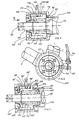
- the brake unit 40 is integrated into the bottom bracket 42 and housed within the bottom bracket housing 4l.
- a clutch disc 43 is placed on the bottom bracket shaft 45 with the interposition of a freewheel 44.
- the freewheel corresponds to the freewheel 24 from FIG. 2 and is oriented in such a way that no torque is transmitted to the clutch disc 43 when the bottom bracket shaft 45 advances, whereas when the bottom bracket shaft 45 rests there is a torsionally rigid coupling and torque is transmitted to the clutch disc 43.
- a brake member 47 corresponding to the brake member 26 is coupled to the clutch disk 43, which is disk-shaped and is rotatably fitted onto the extension of the clutch disk 43.
- the braking member 47 forms a slip clutch 46 with the clutch disc 43.
- the slip clutch 46 is loaded by a spring 48, the load of which can be adjusted with the aid of the cover 50. The setting is secured with the threaded ring 57.
- the cover 50 of the bottom bracket housing can be unscrewed, so that the parts of the brake unit described so far are accessible.
- An actuating arm 5l which corresponds to the actuating arm 30 and is directed radially, is fastened to the braking member 47.
- This actuating arm is led out of the housing through a slot 52 in the housing wall of the bottom bracket housing 4l.
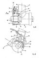
- a Bowden cable 53 corresponding to the Bowden cable l7 is suspended with the same orientation as described in the text for FIGS. 1 and 2.
- the Bowden cable 53 actuates a hub brake, which is shown in Figure l2.
- the actuating arm 5l When moving forward and in the rest position, the actuating arm 5l is in the rest position shown in solid lines in FIG. 4, namely under the action of a restoring spring 54 corresponding to the restoring spring l6, which acts on an actuating lever 55 for the hub brake and is otherwise supported on a frame part 56.
- the actuating arm 5l When withdrawing, the actuating arm 5l swivels as a result of the torque now transmitted to the braking member 47 into the position shown in dashed lines in FIG. 4, in which the brake shoe is braked against the hub.
- the brake unit 10 1 is accommodated in a housing 10 2, which is attached laterally to the bottom bracket housing 10 3.
- a bearing ring l04 with an external thread is used for this purpose, which is screwed to the bottom bracket housing l03 and to the brake unit housing l02.
- a counter ring l05 is screwed onto the bearing ring l04.
- the housing is secured against turning with a grub screw l06.
- the bottom bracket shaft l07 protrudes from the housing l02.
- an adapter sleeve ll0 is inserted, which is firmly connected to the bottom bracket shaft.
- a freewheel sleeve III with the free-wheel surface ll2 is placed over this adapter sleeve ll0.
- a profile piece ll3 is inserted over the freewheel sleeve III and is firmly connected to the freewheel sleeve.
- a brake ring ll9 is positively inserted, which is under the load of a plate spring ll5.
- This disc spring ll5 is supported on a self-locking nut l20, which is screwed to the profile piece ll3.
- the load force exerted by the plate spring ll5 can be adjusted by adjusting the nut l20.
- the brake ring ll9 lies on an annular sliding surface l23 perpendicular to the bottom bracket axis l22 on the profile piece ll3.
- the parts ll0, lll, ll3, ll5 are arranged and designed coaxially to the bottom bracket axis l22
- actuating arm 130 On the brake ring II9 there is a radially extending actuating arm 130, which corresponds to the actuating arm 5l from FIGS. 3 and 4. A slot l32 corresponding to slot 52 is provided for this actuating arm.
- the parts of the bottom bracket visible in FIG. 5 are designed in the same way as in the case of known bottom brackets, so that, apart from the corresponding extension of the bottom bracket shaft, the same components can be used.
- the embodiment shown in Figure 7 differs from the embodiment of Figure 5 only in that it is adapted to a differently designed, known bottom bracket.
- the bottom bracket shell is labeled l50 and the bottom bracket shaft is labeled l5l.
- the brake unit housing l52 is screwed to the bottom bracket housing l50 via an intermediate ring l53.
- a ball bearing cup l57 for the ball bearing l54 is provided with a protruding bead l55.
- the intermediate ring l52 which is mounted between the bead of the ball bearing shell l55 and the bottom bracket shell l50, is fixed using the adjusting nut l58.
- the brake the unit housing is secured with the lock ring l59.
- the exemplary embodiment according to FIG. 7 is designed in exactly the same way as the exemplary embodiment according to FIGS. 5 and 6, and corresponding parts in FIG. 7 are given the same reference numerals as in FIGS. 5 and 6, but with a suffix " ⁇ ".
- the brake unit 70 is housed within the bottom bracket shell 7l. 72 with a braking element is designated, which is inserted with the interposition of a freewheel 75 mounted on both sides on the bottom bracket shaft 76. Due to the freewheeling, when the bottom bracket shaft 76 advances, no torque is transmitted to the braking member 72; on the other hand, torque is transmitted from the bottom bracket shaft 76 to the braking member when the pedal rests.
- a radially directed actuating arm 77 is attached to the braking member 72 and is guided out of the bottom bracket housing 7l through a slot 78.
- the actuating arm is a two-part articulated lever, the outer arm part 85 of which is forced under the force of a return spring 79 against a stop 84 into the radial rest position shown in FIG.
- a Bowden cable 80 is suspended, which is oriented and designed in exactly the same way as the Bowden cable 53 from FIG. 4 and acts on a brake shoe corresponding to the brake shoe 55, which can be attached to the rear wheel rim, against the force of one of the return springs 54 Return spring.
- the pivotal movement of the braking member 72 is limited per se by the limited longitudinal extent of the slot 78.
- the pivoting movement of the braking member is restricted to a narrower angular range by an axially attached to the braking member directed nose 8l, which fits into a curved stationary slot arch 82 attached to the bottom bracket shell 7l.
Landscapes
- Engineering & Computer Science (AREA)
- Mechanical Engineering (AREA)
- Braking Arrangements (AREA)
Applications Claiming Priority (2)
| Application Number | Priority Date | Filing Date | Title |
|---|---|---|---|
| DE3611490 | 1986-04-05 | ||
| DE19863611490 DE3611490A1 (de) | 1986-04-05 | 1986-04-05 | Fahrrad |
Publications (1)
| Publication Number | Publication Date |
|---|---|
| EP0240944A1 true EP0240944A1 (fr) | 1987-10-14 |
Family
ID=6298039
Family Applications (1)
| Application Number | Title | Priority Date | Filing Date |
|---|---|---|---|
| EP87104942A Withdrawn EP0240944A1 (fr) | 1986-04-05 | 1987-04-03 | Bicyclette |
Country Status (2)
| Country | Link |
|---|---|
| EP (1) | EP0240944A1 (fr) |
| DE (1) | DE3611490A1 (fr) |
Cited By (2)
| Publication number | Priority date | Publication date | Assignee | Title |
|---|---|---|---|---|
| DE3828924A1 (de) * | 1988-08-26 | 1990-03-08 | Artur Paeselt | Ruecktrittbremse fuer fahrraeder mit kettenschaltung |
| DE19624464A1 (de) * | 1996-06-19 | 1996-11-07 | Lars Jorde | Felgenbremse eines Fahrrads |
Families Citing this family (4)
| Publication number | Priority date | Publication date | Assignee | Title |
|---|---|---|---|---|
| DE4007865C2 (de) * | 1990-03-13 | 1994-06-23 | Karl Dr Koltai | Fahrradpedal |
| EP0812283A4 (fr) * | 1995-03-17 | 1999-05-12 | Sarun Holdings Limited | Systeme de freins ameliore pour bicyclette ou autres mecanismes entraines par chaine |
| DE19752869A1 (de) | 1997-06-25 | 1999-06-10 | Op Den Camp Eckart | Bremsbetätigungseinrichtung für ein muskelkraftbetriebenes Fahrzeug |
| DE19727052C1 (de) * | 1997-06-25 | 1998-11-12 | Den Camp Eckart Op | Bremsbetätigungseinrichtung für ein muskelkraftbetriebenes Fahrzeug |
Citations (4)
| Publication number | Priority date | Publication date | Assignee | Title |
|---|---|---|---|---|
| GB191409827A (en) * | 1913-06-05 | 1915-04-15 | Albert Aubry | Improvements in or relating to Back-pedalling Brakes for Cycles, Motor Cycles and the like. |
| FR828953A (fr) * | 1937-11-10 | 1938-06-07 | Frein sur jante de bicyclette par rétropédalage | |
| FR870048A (fr) * | 1940-10-22 | 1942-02-27 | Dispositif applicable au freinage des organes en rotation | |
| FR899664A (fr) * | 1943-07-10 | 1945-06-07 | Dispositif pour le freinage de cycles |
-
1986
- 1986-04-05 DE DE19863611490 patent/DE3611490A1/de not_active Withdrawn
-
1987
- 1987-04-03 EP EP87104942A patent/EP0240944A1/fr not_active Withdrawn
Patent Citations (4)
| Publication number | Priority date | Publication date | Assignee | Title |
|---|---|---|---|---|
| GB191409827A (en) * | 1913-06-05 | 1915-04-15 | Albert Aubry | Improvements in or relating to Back-pedalling Brakes for Cycles, Motor Cycles and the like. |
| FR828953A (fr) * | 1937-11-10 | 1938-06-07 | Frein sur jante de bicyclette par rétropédalage | |
| FR870048A (fr) * | 1940-10-22 | 1942-02-27 | Dispositif applicable au freinage des organes en rotation | |
| FR899664A (fr) * | 1943-07-10 | 1945-06-07 | Dispositif pour le freinage de cycles |
Cited By (2)
| Publication number | Priority date | Publication date | Assignee | Title |
|---|---|---|---|---|
| DE3828924A1 (de) * | 1988-08-26 | 1990-03-08 | Artur Paeselt | Ruecktrittbremse fuer fahrraeder mit kettenschaltung |
| DE19624464A1 (de) * | 1996-06-19 | 1996-11-07 | Lars Jorde | Felgenbremse eines Fahrrads |
Also Published As
| Publication number | Publication date |
|---|---|
| DE3611490A1 (de) | 1987-10-08 |
Similar Documents
| Publication | Publication Date | Title |
|---|---|---|
| DE2215333A1 (de) | Scheibenbremse für Fahrräder | |
| DE2638330A1 (de) | Motoranlassvorrichtung fuer ein kraftrad | |
| EP0240944A1 (fr) | Bicyclette | |
| DE19516216C2 (de) | Fahrzeug mit Schubkurbelantrieb | |
| DE8704965U1 (de) | Fahrrad | |
| DE10327970A1 (de) | Muskelkraftbetriebenes Sport- und Spielgerät | |
| DE19702764A1 (de) | Haltevorrichtung für ein Hinterrad eines Fahrrades | |
| DE704585C (de) | Fahrrad mit Hilfsmotorantrieb | |
| DE945738C (de) | Motorrad mit Tretkurbel | |
| DE8507021U1 (de) | Dreirad, insbesondere für behinderte Personen | |
| DE1505927C2 (de) | Kupplungsvorrichtung für Mopeds | |
| DE3904786A1 (de) | Durch gegentreten betaetigte zweiradbremse | |
| DE4218409C2 (de) | Rücktrittbremse bei Naben für Fahrräder oder dergleichen | |
| AT148204B (de) | Freilaufbremsnabe. | |
| DE871701C (de) | Ruecktrittbremsnabe fuer Fahr- und Motorfahrraeder | |
| DE102008004357A1 (de) | Linearer Handantrieb mit Lenkfunktion für ein muskelkraftgetriebenes Leichtfahrzeug | |
| DE4307485A1 (de) | Bremssystem für durch Muskelkraft angetriebene Fahrräder | |
| DE602803C (de) | Freilaufbremsnabe | |
| DE656819C (de) | Tretkurbelsperrvorrichtung fuer Leichtmotorraeder mit Freilauf und Ruecktrittbremse | |
| DE3325073A1 (de) | Fahrzeug, insbesondere fahrrad | |
| DE4226432A1 (de) | Antrieb für Fahrräder, insbesondere für Fahrräder für Gehbehinderte | |
| DE20307034U1 (de) | Roller zur Fortbewegung von Personen | |
| DE576680C (de) | Freilaufnabe mit Ruecktrittbremse und Rueckwaertsantrieb | |
| DE202009005913U1 (de) | Vorrichtung zum Bedienen einer Bremseinrichtung eines Fahrzeugs und Fahrzeug | |
| DE823991C (de) | Ruecktrittbremse fuer Fahrraeder u. dgl. |
Legal Events
| Date | Code | Title | Description |
|---|---|---|---|
| PUAI | Public reference made under article 153(3) epc to a published international application that has entered the european phase |
Free format text: ORIGINAL CODE: 0009012 |
|
| AK | Designated contracting states |
Kind code of ref document: A1 Designated state(s): DE FR GB IT NL |
|
| 17P | Request for examination filed |
Effective date: 19880116 |
|
| 17Q | First examination report despatched |
Effective date: 19881012 |
|
| STAA | Information on the status of an ep patent application or granted ep patent |
Free format text: STATUS: THE APPLICATION IS DEEMED TO BE WITHDRAWN |
|
| 18D | Application deemed to be withdrawn |
Effective date: 19890223 |