EP0213232A1 - Appareil pour le traitement des produits alimentaires - Google Patents
Appareil pour le traitement des produits alimentaires Download PDFInfo
- Publication number
- EP0213232A1 EP0213232A1 EP85111195A EP85111195A EP0213232A1 EP 0213232 A1 EP0213232 A1 EP 0213232A1 EP 85111195 A EP85111195 A EP 85111195A EP 85111195 A EP85111195 A EP 85111195A EP 0213232 A1 EP0213232 A1 EP 0213232A1
- Authority
- EP
- European Patent Office
- Prior art keywords
- drum
- flap
- shaft
- tools
- tool
- Prior art date
- Legal status (The legal status is an assumption and is not a legal conclusion. Google has not performed a legal analysis and makes no representation as to the accuracy of the status listed.)
- Granted
Links
- 238000012545 processing Methods 0.000 title claims abstract description 10
- 238000002156 mixing Methods 0.000 claims abstract description 18
- 239000012780 transparent material Substances 0.000 claims abstract description 4
- 238000007789 sealing Methods 0.000 claims description 13
- 238000004140 cleaning Methods 0.000 claims description 9
- 238000004898 kneading Methods 0.000 claims description 9
- 238000011068 loading method Methods 0.000 claims description 7
- 238000007790 scraping Methods 0.000 claims description 7
- 229910000831 Steel Inorganic materials 0.000 claims description 6
- 238000006073 displacement reaction Methods 0.000 claims description 6
- 239000010959 steel Substances 0.000 claims description 6
- 238000003780 insertion Methods 0.000 claims description 5
- 230000037431 insertion Effects 0.000 claims description 5
- 239000004033 plastic Substances 0.000 claims description 4
- 230000001804 emulsifying effect Effects 0.000 claims description 3
- 238000003756 stirring Methods 0.000 claims description 3
- 239000004952 Polyamide Substances 0.000 claims description 2
- 229920002647 polyamide Polymers 0.000 claims description 2
- XLYOFNOQVPJJNP-UHFFFAOYSA-N water Substances O XLYOFNOQVPJJNP-UHFFFAOYSA-N 0.000 description 6
- 239000000463 material Substances 0.000 description 4
- 238000013461 design Methods 0.000 description 2
- 238000011010 flushing procedure Methods 0.000 description 2
- 241001295925 Gegenes Species 0.000 description 1
- 241001465754 Metazoa Species 0.000 description 1
- 238000009529 body temperature measurement Methods 0.000 description 1
- 238000001816 cooling Methods 0.000 description 1
- 230000003670 easy-to-clean Effects 0.000 description 1
- 238000011049 filling Methods 0.000 description 1
- 238000010438 heat treatment Methods 0.000 description 1
- 230000001771 impaired effect Effects 0.000 description 1
- 239000004615 ingredient Substances 0.000 description 1
- 239000002184 metal Substances 0.000 description 1
- 238000000034 method Methods 0.000 description 1
- 239000003973 paint Substances 0.000 description 1
- 229920000642 polymer Polymers 0.000 description 1
- 239000008237 rinsing water Substances 0.000 description 1
- 210000002023 somite Anatomy 0.000 description 1
Images


Classifications
-
- A—HUMAN NECESSITIES
- A21—BAKING; EDIBLE DOUGHS
- A21C—MACHINES OR EQUIPMENT FOR MAKING OR PROCESSING DOUGHS; HANDLING BAKED ARTICLES MADE FROM DOUGH
- A21C1/00—Mixing or kneading machines for the preparation of dough
- A21C1/06—Mixing or kneading machines for the preparation of dough with horizontally-mounted mixing or kneading tools; Worm or screw mixers
Definitions
- the invention relates to a food processing device with a drum lying at a clear distance above the floor on a base frame, which has a closable upper inlet, a lower outlet slide and a hinged front cover, in the center of which is provided an angularly designed transport wing provided with its own drive , whose horizontal leg rests with a scraping edge on the inner wall of the drum shell of the drum, in which a horizontal tool shaft is overhung parallel to and below its drum axis, the interchangeable tools for crushing, cutting, rubbing, stirring, mixing, quantity, emulsifying and / or carries kneading, protrudes through the rear end wall of the drum and is in rotary connection with a main motor also arranged on the base frame.
- Such an embodiment can be found in DE-B-24 34 330. Due to the downward, eccentric arrangement of the tool shaft, even small quantities can be processed with the tools; good mixing is also achieved.
- the drum can hold about 150 l, for example, so that up to 100 kg of mass can be processed in the drum.
- the invention is therefore based on the object of designing the device explained at the outset so that in particular the outlet slide, the transport wing and the tool shaft can be cleaned easily, quickly and reliably.
- the drop frame has sealing surfaces assigned to the strips of the outlet slide, which are made of Steel exist and are only a few millimeters wide and raised a few tenths of a millimeter.
- the holding and tensioning device for each guide rail consists of an angle piece fastened to the drop frame, which engages with its vertical leg in a longitudinal groove of a tensioning plate fastened to the guide rail, which carries an upwardly projecting threaded bolt which is guided by a Insert slot of the contra-angle protrudes from the side and carries a tension nut on its free end, which presses on the contra-angle via a disc spring.
- the outlet slide can be removed quickly and easily by simply loosening the two clamping nuts.
- a defined contact pressure can be achieved between the sealing surfaces mentioned and the longitudinal strips of the outlet slide. This ensures a reliable seal and at the same time a jam-free and jerk-free displacement of the outlet slide.
- the above-mentioned design of the sealing surfaces ensures a sufficiently large surface pressure and minimizes wear. Sealing, wear and sliding properties of the outlet slide are optimal if the outlet slide is made of polyamide. This material also enables easy and reliable cleaning of the slide.
- the sliding seals for the transport wing and the tool shaft preferably each consist of two identical steel rings with a rubber sleeve.
- the transport wing is, according to the invention, inserted with a bushing which acts on the sliding seal on the drive shaft which projects through the end cover and is designed as a spline shaft and is detachably fixed by a large cap nut which is screwed onto a threaded bolt fastened to the end face of the spline shaft and with an annular sealing lip against the aforementioned Socket is pressed.
- the clamping nut acting on the sliding seal of the tool shaft is preferably a bayonet ring.
- the upper inlet of the drum can be arranged in the drum casing somewhat below its highest point towards the operating side. This allows the device to be operated easily even by medium-sized people, despite its large capacity. Nevertheless, there are various alternatives for the removal of the finished product. So the drum can be placed on the base frame so high that e.g. can push a container car or a conveyor belt device.
- the upper loading opening can be closed by a flap, which is made of transparent material, is contoured on its inside and is detachably held on a pivot axis lying parallel to the drum axis.
- a flap which is made of transparent material, is contoured on its inside and is detachably held on a pivot axis lying parallel to the drum axis.
- the transparent flap is designed to follow the contour on its inside, the transport wing with its scraping edge would also paint over the flap. With masses that tend to smear, the transparency of the flap is greatly impaired. It can therefore be advantageous if at least one partial area the contour-following inner surface of the flap is set back somewhat from the inner surface of the drum shell. The flap remains clear in this area even when the inner surface is set back by about 1 mm.
- the loading of the drum can also be done via a snorkel, funnel, a hose or the like. take place fully automatically.
- the flap is then replaced by a fixed funnel with appropriate connections.
- the drum jacket can be designed as a double wall if cooling and / or heating of the drum is desired.
- the device can also be designed for operation in negative or positive pressure. It can then steam valves or the like opening into the drum. be provided.
- thermometer expediently protrudes into the drum for exact temperature measurement.
- a time selection clock for default control and termination e.g. the kneading times may be provided.
- a power time recorder or a current time recorder can also be provided. The optimal kneading process or the optimal introduction of energy into the mass to be prepared can then be read from the records.
- claims 10 to 13 result in an easily removable or installable flap which can be cleaned easily and quickly.
- the toggle handle in the plate can also be removed quickly.
- the pocket-shaped undercut is as large as possible and is designed with flat curves, so that safe and easy cleaning is also possible here.
- the drain opening mentioned allows material which has remained or has sprayed out when the flap is opened to flow back into the interior of the drum.
- the drain opening is provided in the lower-lying funnel longitudinal wall, the inner surface of which is opposite the horizontal is only inclined flat upwards.
- the invention has created a functionally reliable, user-friendly food processing machine, the inlet and outlet of which have an uncomplicated design and can be water-tight and possibly also vacuum-tight.
- the new device meets the highest hygiene requirements while avoiding gaps and difficult-to-clean areas in the food zones. For easy cleaning, the parts in the food zone area can be assembled and disassembled in a few simple steps.
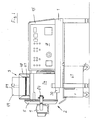
- the food processing device shown in particular in FIGS. 1 and 7 comprises a mixing drum 2 which is arranged at a clear distance above the floor on a base frame 1 and which has a closable upper inlet 3 and a lower outlet slide 4.
- an end cover 5 is articulated, which can be pivoted about a vertical axis 6.
- Angled transport wing 8 is mounted, the horizontal leg 8a of which rests with a scraping edge 9 on the inner wall of the drum casing 2a of the mixing drum 2 (see also FIG. 8).
- a horizontal tool shaft 10 is overhung in the mixing drum 2 and lies parallel to and below the central drum axis 11.
- the mixing drum 2 is flanged on its rear end wall 12 with a main motor 13 which drives the tool shaft 10 projecting through the rear end wall 12.
- Mixing drum 2 and main motor 13 are mounted on vibrating metal 14 on the top of the base frame 1.
- the main motor 13 is located within a housing cover 15, which i.a. encloses a hydraulic drive 16 for actuating the outlet slide 4.
- a water metering line 17 is welded into the upper region of the rear end wall 12, from which water can be sprayed against the inner wall of the drum casing 2a at a defined angle.
- the one-piece outlet slider 4 is contoured on its side facing the interior of the mixing drum 2, that is to say it lies exactly inside the inner contour of the mixing drum 2.
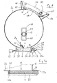
- the lower discharge opening 19 is surrounded by a drop frame 20 which is made of steel and is only a few millimeters wide and a few Has tenths of a millimeter raised sealing surfaces 21 which cooperate with the top of two longitudinal strips 22 arranged on the circumference of the outlet slide 4.
- the guide for the outlet slide 4 consists of two guide strips 23 arranged in the direction of displacement and engaging under the two longitudinal strips 22, each of which is detachably attached to a holding and tensioning device attached to the drop frame 20 hang.
- the latter consists of an angle piece 24 fastened to the drop frame 20, which engages with its vertical leg 24a into a longitudinal groove of a clamping plate 25 fastened to the guide bar 23.
- This clamping plate 25 carries an upwardly projecting threaded bolt 26 which projects through an insertion slot 27 of the angle piece 24 which is open to the side and carries on its free end a tension nut 28 which presses on the angle piece 24 via a plate spring 29.
- Comparable sealing surfaces 21 interact with cross strips 22a provided in the two end regions of the outlet slide 4 (see FIG. 7d).
- the outlet slide 4 hangs on a hydraulic rod 30 actuated by the hydraulic drive 16.
- the outlet slide 4 acts on a limit switch 32 (see FIG. 8), which in this position releases various functions of the device.
- a central passage opening 33 is provided through which a spline shaft 34 acted upon by the drive 7 projects, onto which the transport wing 8 with a bush 35 is pushed in a rotationally fixed manner.
- the passage opening 33 has a considerably larger diameter than the spline shaft 34.
- a sliding seal 36 which consists of two identical steel rings with a rubber sleeve, is pushed into the annular space formed in this way.
- a large-sized cap nut 38 is screwed onto a threaded bolt 37 fastened to the end face of the spline shaft 34. When tightened with an annular sealing lip 39, it presses the bush 35 against the sliding seal 36 and thereby deforms it radially outwards (see FIG. 7a).
- the seal between the rear end wall 12 and the tool shaft 10 corresponds essentially to the type explained above, wherein instead of the threaded bolt 37 with the cap nut 38, a clamping nut 40 in the form of a bayonet ring is provided, which is pushed onto the tool shaft 10 and is with the help of a Let the clamping tool be screwed into a corresponding receptacle of the rear end wall 12, the sliding seal 36 located in the annular space between the tool shaft 10 and the end wall 12 being acted upon and deformed outward in the radial direction (see FIG. 7c).
- the tool shaft 10 can rotate at 750-1,200 rpm when the food processing device is used as a kneading machine.
- the scraping edge 9 of the transport wing 8 consists of a plastic strip which is easily detachably fixed by a clamping strip 41 screwed to the horizontal leg 8a (see FIG. 8).
- the free end of the tool shaft 10 has an undercut radial slot 42 which is open to the front and into which a cross bolt 43 is inserted into the tool shaft 10
- Tool sleeve 44 engages, which carries the tools 45 and at their end facing the end cover 5 an annular collar 46 which has a small clear distance a from the cap 8 which defines the transport wing 8 (see FIGS. 7a + 7b).
- Transport wing 8 and tools 45 can be assembled and disassembled quickly and easily.
- the cap nut 38 is loosened, whereupon the transport wing 8 can be pulled off the spline shaft 34.
- the sliding seal 36 can then be pulled out.
- the annular space between the spline shaft 34 and the end cover 5 is exposed, so that a simple flushing through this annular space is possible for cleaning; the rinse water then escapes to the outside.
- the scraping edge 9 can be removed and cleaned quickly and easily.
- the tool sleeve 44 only needs to be pulled off the tool shaft 10.
- the resulting annular space between the tool shaft 10 and the rear end wall 12 can also be flushed from the inside to the outside, the rinsing water outside the mixing drum 2 between its rear end wall 12 and the flanged main motor 13 exit.
- the transport wing and tools are installed accordingly. If the tool shaft 10 starts up when the device is started up, there is a slight relative rotation between the tool sleeve 44 and the tool shaft 10 due to the inertia or a resistance exerted on the tools 45 and thus an automatic locking by the cross bolt 43 engaging behind the undercut of the radial slot 42 . Should there nevertheless be a displacement of the tool sleeve 44 on the tool shaft 10 in the axial direction, then the collar 46 of the tool sleeve 44 would immediately put on the cap nut 38 and thus limit the axial displacement and un make harmful.
- the tool sleeve 44 can carry tools for comminuting, cutting, rubbing, stirring, mixing, quantity, emulsifying and / or kneading.
- FIGS. 7 and 8 show an example of a kneading tool which is particularly suitable for firmer doughs.
- the tool sleeve 44 carries two identically designed U-shaped kneading tools 45, which are offset from one another by 180 ° and fastened at an axial distance from one another on the opposite sides of the tool sleeve 44 such that the ends of the adjacent U-legs 45a of the two tools 45 lie on one sleeve side and that of the two axially outermost U-legs 45b on the other sleeve side (see FIG. 7).
- the two tools 45 together form an apparently closed curve in the form of a flat rectangle (see FIG. 8).
- the two tools 45 are bent from round material and are therefore very easy to clean.
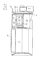
- FIGS. 5 and 8 show that the upper inlet 3 of the mixing drum 2 in the drum casing 2a can be arranged somewhat below its highest point on the operating side. This arrangement is useful if the loading of the mixing drum 2 is done manually and at the same time a possibility to observe the interior of the drum is to be provided.
- an upper loading opening 47 is surrounded on all sides by a flat funnel 48, which consists of hollow walls and comprises a flap 49. This consists of transparent material and is contoured on the inside; it is detachably held on its higher longitudinal edge on a pivot axis 50 lying parallel to the drum axis 11.
- the pivot axis 50 has two plug pins 51 connected to the flap 49, of which one plug pin is axially inserted into a first eyelet 52, while the other plug pin is connected a flattening (not shown) in the radial direction is pushed into a correspondingly dimensioned insertion slot 53 of a second eyelet 52.
- the flap 49 is locked via a pivotable toggle handle 54, which is detachably fixed to the flap 49 via a screw connection 55.
- the funnel 48 has in its longitudinal wall remote from the animal a pocket-shaped undercut 56 for engagement with the toggle handle 54.
- a support collar 57 possibly formed by the drum casing 2a, is provided for the flap 49 within the funnel 48.
- this support collar 57 has a recess forming a drain opening 58, into which the flap engages flush with a correspondingly dimensioned sealing strip 59 when the flap 49 is closed.
- the inner surface 60 of the lower-lying longitudinal wall of the funnel 48 is only inclined flatly upwards with respect to the horizontal (see in particular FIG. 8).
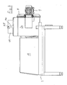
- Figure 6 shows a modified embodiment for the upper inlet 3.
- the upper inlet 3 lies at the highest point of the drum casing 2a and is overlapped on all sides by a connecting piece 61 which has hose and pipe connections 62 and a viewing and operating flap 63.
- the front cover 5 has an eccentric toggle lever lock 64, which comprises an easily removable axis of rotation 66 which supports the hand lever 65.
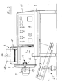
- a container trolley 67 which can be pulled out of the base frame 1 is arranged below the outlet slide 4 and, in the filling position shown, acts on a stop switch (not shown). When the container car 67 is pulled out, this stop switch stops the machine.
- a conveyor 69 is under the Aus instead of a container wagon slide slide 4 pushed.
- FIGs 1, 2, 3 and 5 show the flap 49 in the open position, while this flap is closed in the representations in Figures 4 and 8.
- the flap has been omitted for clarity.
- the flap is locked via a magnetic switch, not shown. If a working operation under vacuum is provided for the device, the flap 49 is provided with a corresponding seal.
- a position circuit is provided for the transport wing 8 to ensure that the transport wing does not stop below the upper inlet 3 or above the outlet slide 4.
- the front cover 5 acts in its closed position on a limit switch, not shown, which stops the machine when the front cover is opened.
Landscapes
- Life Sciences & Earth Sciences (AREA)
- Engineering & Computer Science (AREA)
- Food Science & Technology (AREA)
- Food-Manufacturing Devices (AREA)
- Accessories For Mixers (AREA)
- Formation And Processing Of Food Products (AREA)
- General Preparation And Processing Of Foods (AREA)
- Mixers Of The Rotary Stirring Type (AREA)
- Manufacturing And Processing Devices For Dough (AREA)
- Apparatuses For Bulk Treatment Of Fruits And Vegetables And Apparatuses For Preparing Feeds (AREA)
- Electrical Discharge Machining, Electrochemical Machining, And Combined Machining (AREA)
- Control And Other Processes For Unpacking Of Materials (AREA)
- Refuse Collection And Transfer (AREA)
- Bakery Products And Manufacturing Methods Therefor (AREA)
Priority Applications (16)
| Application Number | Priority Date | Filing Date | Title |
|---|---|---|---|
| EP85111195A EP0213232B1 (fr) | 1985-09-05 | 1985-09-05 | Appareil pour le traitement des produits alimentaires |
| AT85111195T ATE35498T1 (de) | 1985-09-05 | 1985-09-05 | Nahrungsmittelverarbeitungsvorrichtung. |
| DE8585111195T DE3563587D1 (en) | 1985-09-05 | 1985-09-05 | Food-processing apparatus |
| US06/812,846 US4650337A (en) | 1985-09-05 | 1985-12-23 | Food processing device |
| ZA866651A ZA866651B (en) | 1985-09-05 | 1986-09-02 | Food processing device |
| DD86294152A DD249400A5 (de) | 1985-09-05 | 1986-09-04 | Nahrungsmittelverarbeitungsvorrichtung |
| BR8604256A BR8604256A (pt) | 1985-09-05 | 1986-09-04 | Dispositivo para o processamento de alimentos |
| ES8601616A ES2001653A6 (es) | 1985-09-05 | 1986-09-04 | Dispositivo de elaboracion de alimentos |
| SU864028156A SU1607682A3 (ru) | 1985-09-05 | 1986-09-04 | Универсальна машина дл обработки пищевых продуктов |
| CN86105937A CN1008683B (zh) | 1985-09-05 | 1986-09-05 | 食品加工机械 |
| YU1555/86A YU44593B (en) | 1985-09-05 | 1986-09-05 | Device for food working |
| CA000517598A CA1259067A (fr) | 1985-09-05 | 1986-09-05 | Dispositif pour le traitement des aliments |
| JP61209398A JPH0755123B2 (ja) | 1985-09-05 | 1986-09-05 | 食品加工装置 |
| HR921260A HRP921260B1 (en) | 1985-09-05 | 1992-11-13 | Food processing apparatus |
| LTRP200A LT2031B (lt) | 1985-09-05 | 1992-12-17 | Universali maisto produktu apdirbimo masina |
| LV930005A LV5169A3 (lv) | 1985-09-05 | 1993-01-08 | Universala masina partikas produktu apstradei |
Applications Claiming Priority (1)
| Application Number | Priority Date | Filing Date | Title |
|---|---|---|---|
| EP85111195A EP0213232B1 (fr) | 1985-09-05 | 1985-09-05 | Appareil pour le traitement des produits alimentaires |
Publications (2)
| Publication Number | Publication Date |
|---|---|
| EP0213232A1 true EP0213232A1 (fr) | 1987-03-11 |
| EP0213232B1 EP0213232B1 (fr) | 1988-07-06 |
Family
ID=8193738
Family Applications (1)
| Application Number | Title | Priority Date | Filing Date |
|---|---|---|---|
| EP85111195A Expired EP0213232B1 (fr) | 1985-09-05 | 1985-09-05 | Appareil pour le traitement des produits alimentaires |
Country Status (14)
| Country | Link |
|---|---|
| US (1) | US4650337A (fr) |
| EP (1) | EP0213232B1 (fr) |
| JP (1) | JPH0755123B2 (fr) |
| CN (1) | CN1008683B (fr) |
| AT (1) | ATE35498T1 (fr) |
| BR (1) | BR8604256A (fr) |
| CA (1) | CA1259067A (fr) |
| DD (1) | DD249400A5 (fr) |
| DE (1) | DE3563587D1 (fr) |
| ES (1) | ES2001653A6 (fr) |
| LT (1) | LT2031B (fr) |
| SU (1) | SU1607682A3 (fr) |
| YU (1) | YU44593B (fr) |
| ZA (1) | ZA866651B (fr) |
Cited By (1)
| Publication number | Priority date | Publication date | Assignee | Title |
|---|---|---|---|---|
| WO1995014386A1 (fr) * | 1993-11-20 | 1995-06-01 | Ismar Maschinen Gmbh | Machine a petrir |
Families Citing this family (34)
| Publication number | Priority date | Publication date | Assignee | Title |
|---|---|---|---|---|
| DE3831609A1 (de) * | 1988-09-17 | 1990-03-22 | Loedige Maschbau Gmbh Geb | Maschine zum behandeln schuettfaehiger, pastoeser und/oder fliessfaehiger gueter mit eingebauter aufschliessvorrichtung |
| DE4137161C2 (de) * | 1991-11-12 | 1994-02-24 | Stephan & Soehne | Verfahren zur Teigbereitung |
| US5176069A (en) * | 1992-06-02 | 1993-01-05 | Chen Hsing W | Mechanism for drying and frying meat |
| JP2829462B2 (ja) * | 1992-09-16 | 1998-11-25 | ハウス食品株式会社 | ドウミキサー |
| ES2133021B1 (es) * | 1995-06-12 | 2000-04-01 | Merino Cuesta Joaquin | Perfeccionamientos introducidos en maquinas batidoras, mezcladoras y amasadoras. |
| US5727876A (en) * | 1996-05-31 | 1998-03-17 | E. I. Du Pont De Nemours And Company | Polymer mixing apparatus |
| US6863429B2 (en) * | 2002-01-07 | 2005-03-08 | Artos, S.A. | Dough mixer with metering device |
| US6793386B2 (en) * | 2001-08-15 | 2004-09-21 | Morinaga & Co., Ltd. | Kneading device |
| RU2262876C1 (ru) * | 2004-04-12 | 2005-10-27 | Салдаев Геннадий Александрович | Универсальная машина для обработки пищевых продуктов |
| RU2258449C1 (ru) * | 2004-04-12 | 2005-08-20 | Федеральное государственное образовательное учреждение высшего профессионального образования "Волгоградская государственная сельскохозяйственная академия" | Универсальная машина для обработки пищевых продуктов |
| FR2883704B1 (fr) * | 2005-04-05 | 2007-06-01 | Vmi Sa | Dispositif de melange en continu d'une pate alimentaire comprenant deux types d'outils de melange superposes et evacuation laterale |
| DE102007050858A1 (de) * | 2007-10-24 | 2009-04-30 | Weber Maschinenbau Gmbh Breidenbach | Vorrichtung zum Aufschneiden eines Lebensmittelprodukts |
| RU2351273C1 (ru) * | 2007-12-03 | 2009-04-10 | Федеральное государственное образовательное учреждение высшего профессионального образования "Волгоградская государственная сельскохозяйственная академия" | Универсальная машина для обработки пищевых продуктов |
| US8382365B2 (en) | 2008-03-28 | 2013-02-26 | Oshikiri Machinery Ltd. | Horizontal mixer |
| JP5334744B2 (ja) * | 2009-08-14 | 2013-11-06 | 株式会社オシキリ | 横型ミキサー |
| JP5197095B2 (ja) * | 2008-03-28 | 2013-05-15 | 株式会社オシキリ | 横型ミキサー |
| ES1070102Y (es) * | 2009-03-30 | 2009-10-16 | Bonas Juan Vila | Maquina picadora y mezcladora de carne, de operatividad alternativa |
| CN103029150A (zh) * | 2012-12-18 | 2013-04-10 | 苏州麦克食品机械塑胶有限公司 | 一种食品加工切割设备 |
| US9713893B2 (en) * | 2013-07-09 | 2017-07-25 | Wenger Manufacturing, Inc. | Method of preconditioning comestible materials using steam/water static mixer |
| KR101529426B1 (ko) * | 2013-08-30 | 2015-06-16 | 가부시끼 가이샤 구보다 | 식재 혼합기 |
| ITTO20130716A1 (it) * | 2013-09-05 | 2015-03-06 | Sancassiano Spa | Vasca per macchina impastatrice |
| CN107155293B (zh) * | 2014-07-03 | 2019-12-13 | 伊莱克斯公司 | 家用电器搅拌装置 |
| CN106455585A (zh) | 2014-07-03 | 2017-02-22 | 伊莱克斯公司 | 家用电器搅拌装置 |
| CN104457139B (zh) * | 2014-12-09 | 2016-04-27 | 青海林丰农牧机械制造有限公司 | 一种药材揉搓机 |
| CN104542781A (zh) * | 2015-01-24 | 2015-04-29 | 朱建国 | 面糊自动输出搅拌机 |
| CN106614855A (zh) * | 2015-10-29 | 2017-05-10 | 重庆市南川区云都挂面厂 | 低噪声和面机 |
| RU2620791C1 (ru) * | 2016-05-28 | 2017-05-29 | Федеральное государственное бюджетное образовательное учреждение высшего образования "Юго-Западный государственный университет" (ЮЗГУ) | Смеситель-эмульсатор |
| CN107836481A (zh) * | 2016-09-20 | 2018-03-27 | 苏州润桐专利运营有限公司 | 一种带挤压的搅拌和面机 |
| CN106614876B (zh) * | 2016-12-07 | 2022-03-04 | 北京金瑞典膳科技有限公司 | 一种家用面条机 |
| RU2674196C1 (ru) * | 2018-01-09 | 2018-12-05 | Акционерное общество "Федеральный научно-производственный центр "Алтай" | Передвижной смеситель компонентов смесевого ракетного твердого топлива гравитационного типа |
| DE102018106189A1 (de) * | 2018-03-16 | 2019-09-19 | Maschinenfabrik Gustav Eirich Gmbh & Co. Kg | Hygienemischer |
| RU2682483C9 (ru) * | 2018-08-01 | 2019-05-16 | Общество с ограниченной ответственностью "АКМАЛЬКО ИНЖИНИРИНГ" | Смесительно-взбивальная машина и способ производства бездрожжевого теста с её использованием |
| CN111298704A (zh) * | 2020-02-28 | 2020-06-19 | 山东理工职业学院 | 一种可倾斜式食品加工搅拌机 |
| CN111605978B (zh) * | 2020-05-25 | 2021-07-02 | 安徽省好朋友食品有限公司 | 一种巧克力生产用防跑偏输送设备 |
Citations (5)
| Publication number | Priority date | Publication date | Assignee | Title |
|---|---|---|---|---|
| DE172211C (fr) * | ||||
| US172513A (en) * | 1876-01-18 | Improvement in folding wardrobes | ||
| US2837356A (en) * | 1955-09-15 | 1958-06-03 | J H Day Company Inc | Sanitary stuffing box |
| GB1064641A (en) * | 1964-04-09 | 1967-04-05 | Royal Industries | Mixing apparatus |
| US4075713A (en) * | 1976-11-11 | 1978-02-21 | Easton Harlan J | Feed mixer |
Family Cites Families (4)
| Publication number | Priority date | Publication date | Assignee | Title |
|---|---|---|---|---|
| AT329398B (de) * | 1970-07-08 | 1976-05-10 | Stephan & Soehne | Nahrungsmittelverarbeitungsvorrichtung |
| US3727893A (en) * | 1971-07-19 | 1973-04-17 | Int Automation Inc | Apparatus for processing rubber, plastic and the like and parts thereof |
| DE2434330A1 (de) * | 1974-07-17 | 1976-01-29 | Stephan & Soehne | Teigmisch- und knetmaschine |
| JPS5914250B2 (ja) * | 1981-02-06 | 1984-04-03 | 正夫 森山 | 混練機等の漏洩防止装置 |
-
1985
- 1985-09-05 DE DE8585111195T patent/DE3563587D1/de not_active Expired
- 1985-09-05 AT AT85111195T patent/ATE35498T1/de not_active IP Right Cessation
- 1985-09-05 EP EP85111195A patent/EP0213232B1/fr not_active Expired
- 1985-12-23 US US06/812,846 patent/US4650337A/en not_active Expired - Lifetime
-
1986
- 1986-09-02 ZA ZA866651A patent/ZA866651B/xx unknown
- 1986-09-04 ES ES8601616A patent/ES2001653A6/es not_active Expired
- 1986-09-04 SU SU864028156A patent/SU1607682A3/ru active
- 1986-09-04 DD DD86294152A patent/DD249400A5/de not_active IP Right Cessation
- 1986-09-04 BR BR8604256A patent/BR8604256A/pt unknown
- 1986-09-05 CA CA000517598A patent/CA1259067A/fr not_active Expired
- 1986-09-05 JP JP61209398A patent/JPH0755123B2/ja not_active Expired - Lifetime
- 1986-09-05 YU YU1555/86A patent/YU44593B/xx unknown
- 1986-09-05 CN CN86105937A patent/CN1008683B/zh not_active Expired
-
1992
- 1992-12-17 LT LTRP200A patent/LT2031B/xx unknown
Patent Citations (5)
| Publication number | Priority date | Publication date | Assignee | Title |
|---|---|---|---|---|
| DE172211C (fr) * | ||||
| US172513A (en) * | 1876-01-18 | Improvement in folding wardrobes | ||
| US2837356A (en) * | 1955-09-15 | 1958-06-03 | J H Day Company Inc | Sanitary stuffing box |
| GB1064641A (en) * | 1964-04-09 | 1967-04-05 | Royal Industries | Mixing apparatus |
| US4075713A (en) * | 1976-11-11 | 1978-02-21 | Easton Harlan J | Feed mixer |
Cited By (2)
| Publication number | Priority date | Publication date | Assignee | Title |
|---|---|---|---|---|
| WO1995014386A1 (fr) * | 1993-11-20 | 1995-06-01 | Ismar Maschinen Gmbh | Machine a petrir |
| US5758962A (en) * | 1993-11-20 | 1998-06-02 | Ismar Maschinen Gmbh | Continuous kneading machine for doughs |
Also Published As
| Publication number | Publication date |
|---|---|
| ZA866651B (en) | 1987-04-29 |
| US4650337A (en) | 1987-03-17 |
| BR8604256A (pt) | 1987-05-05 |
| SU1607682A3 (ru) | 1990-11-15 |
| YU155586A (en) | 1988-08-31 |
| ES2001653A6 (es) | 1988-06-01 |
| LT2031B (lt) | 1993-04-15 |
| JPS62201536A (ja) | 1987-09-05 |
| ATE35498T1 (de) | 1988-07-15 |
| CN1008683B (zh) | 1990-07-11 |
| CN86105937A (zh) | 1987-04-01 |
| CA1259067A (fr) | 1989-09-05 |
| DD249400A5 (de) | 1987-09-09 |
| DE3563587D1 (en) | 1988-08-11 |
| JPH0755123B2 (ja) | 1995-06-14 |
| YU44593B (en) | 1990-10-31 |
| EP0213232B1 (fr) | 1988-07-06 |
Similar Documents
| Publication | Publication Date | Title |
|---|---|---|
| EP0213232B1 (fr) | Appareil pour le traitement des produits alimentaires | |
| EP0225495B1 (fr) | Mélangeur | |
| EP0196291B1 (fr) | Dispositif de mélange | |
| DE2113182C3 (de) | Misch- und Knetmaschine | |
| CH679290A5 (fr) | ||
| DE69905372T2 (de) | Vorrichtung zur herstellung von teigwaren | |
| DE2000395A1 (de) | Knet- und Mischmaschine fuer Fleisch- und Wurstwaren | |
| DD244697A5 (de) | Auspressfilter fuer suspensionen | |
| EP0188717B1 (fr) | Mélangeur | |
| DE2852532B2 (de) | Haushaltsmaschinen zum Herstellen und Ausformen von Teigwaren | |
| DE3837763A1 (de) | Mischvorrichtung | |
| DE2304400A1 (de) | Misch- und mahlvorrichtung fuer ein gestueckeltes, mahlfaehiges material, beispielsweise rohes, grob geschnittenes fleisch | |
| DE2918768C2 (de) | Verfahren zum Entnehmen von Stoffproben aus einem Behälter und Vorrichtung zur Durchführung des Verfahrens | |
| DE102008013393A1 (de) | Vorrichtung zum Fördern und Bearbeiten von Lebensmitteln | |
| EP0664245B1 (fr) | Dispositif pour tester des sacs gonflables | |
| DE60306914T2 (de) | Selbstgespeiste Zerkleinerungsvorrichtung für späneentfernende Werkzeugmaschinen | |
| DE3941836A1 (de) | Reibeeinrichtung | |
| DE29509271U1 (de) | Feststoffmühle | |
| CA3223146A1 (fr) | Appareil de transformation pour des denrees alimentaires | |
| DE69114521T2 (de) | Anlage zum verdichten von abfällen und entsprechende vorrichtung. | |
| DE2845689C3 (de) | Schneidgerät zum Zerkleinern von Nahrungsmitteln, wie Fleisch, Zwiebel, Gemüse o.dgl. | |
| DE7707226U1 (de) | Vorrichtung zur herstellung von angemachtem moertel o.dgl. | |
| DE20313741U1 (de) | Mischeinrichtung für mobile Mahl- und Mischanlagen | |
| CH368614A (de) | Diskontinuierlich arbeitende Misch- und Knetvorrichtung für Gummi- und Kunststoffmassen | |
| DE8902531U1 (de) | Reibeeinrichtung |
Legal Events
| Date | Code | Title | Description |
|---|---|---|---|
| PUAI | Public reference made under article 153(3) epc to a published international application that has entered the european phase |
Free format text: ORIGINAL CODE: 0009012 |
|
| 17P | Request for examination filed |
Effective date: 19860626 |
|
| AK | Designated contracting states |
Kind code of ref document: A1 Designated state(s): AT BE CH DE FR GB IT LI NL SE |
|
| ITCL | It: translation for ep claims filed |
Representative=s name: MODIANO & ASSOCIATI S.R.L. |
|
| TCNL | Nl: translation of patent claims filed | ||
| EL | Fr: translation of claims filed | ||
| 17Q | First examination report despatched |
Effective date: 19870626 |
|
| GRAA | (expected) grant |
Free format text: ORIGINAL CODE: 0009210 |
|
| AK | Designated contracting states |
Kind code of ref document: B1 Designated state(s): AT BE CH DE FR GB IT LI NL SE |
|
| REF | Corresponds to: |
Ref document number: 35498 Country of ref document: AT Date of ref document: 19880715 Kind code of ref document: T |
|
| GBT | Gb: translation of ep patent filed (gb section 77(6)(a)/1977) | ||
| REF | Corresponds to: |
Ref document number: 3563587 Country of ref document: DE Date of ref document: 19880811 |
|
| ET | Fr: translation filed | ||
| ITF | It: translation for a ep patent filed | ||
| PLBE | No opposition filed within time limit |
Free format text: ORIGINAL CODE: 0009261 |
|
| STAA | Information on the status of an ep patent application or granted ep patent |
Free format text: STATUS: NO OPPOSITION FILED WITHIN TIME LIMIT |
|
| 26N | No opposition filed | ||
| ITTA | It: last paid annual fee | ||
| EAL | Se: european patent in force in sweden |
Ref document number: 85111195.5 |
|
| PGFP | Annual fee paid to national office [announced via postgrant information from national office to epo] |
Ref country code: CH Payment date: 19970925 Year of fee payment: 13 |
|
| PG25 | Lapsed in a contracting state [announced via postgrant information from national office to epo] |
Ref country code: LI Free format text: LAPSE BECAUSE OF NON-PAYMENT OF DUE FEES Effective date: 19980930 Ref country code: CH Free format text: LAPSE BECAUSE OF NON-PAYMENT OF DUE FEES Effective date: 19980930 |
|
| REG | Reference to a national code |
Ref country code: CH Ref legal event code: PL |
|
| PGFP | Annual fee paid to national office [announced via postgrant information from national office to epo] |
Ref country code: SE Payment date: 19990823 Year of fee payment: 15 |
|
| PGFP | Annual fee paid to national office [announced via postgrant information from national office to epo] |
Ref country code: GB Payment date: 19990901 Year of fee payment: 15 |
|
| PGFP | Annual fee paid to national office [announced via postgrant information from national office to epo] |
Ref country code: FR Payment date: 19990924 Year of fee payment: 15 |
|
| PGFP | Annual fee paid to national office [announced via postgrant information from national office to epo] |
Ref country code: BE Payment date: 19990929 Year of fee payment: 15 Ref country code: AT Payment date: 19990929 Year of fee payment: 15 |
|
| PGFP | Annual fee paid to national office [announced via postgrant information from national office to epo] |
Ref country code: NL Payment date: 19990930 Year of fee payment: 15 |
|
| PG25 | Lapsed in a contracting state [announced via postgrant information from national office to epo] |
Ref country code: GB Free format text: LAPSE BECAUSE OF NON-PAYMENT OF DUE FEES Effective date: 20000905 Ref country code: AT Free format text: LAPSE BECAUSE OF NON-PAYMENT OF DUE FEES Effective date: 20000905 |
|
| PG25 | Lapsed in a contracting state [announced via postgrant information from national office to epo] |
Ref country code: SE Free format text: THE PATENT HAS BEEN ANNULLED BY A DECISION OF A NATIONAL AUTHORITY Effective date: 20000929 |
|
| PG25 | Lapsed in a contracting state [announced via postgrant information from national office to epo] |
Ref country code: BE Free format text: LAPSE BECAUSE OF NON-PAYMENT OF DUE FEES Effective date: 20000930 |
|
| BERE | Be: lapsed |
Owner name: A. STEPHAN U. SOHNE G.M.B.H. & CO. Effective date: 20000930 |
|
| PG25 | Lapsed in a contracting state [announced via postgrant information from national office to epo] |
Ref country code: NL Free format text: LAPSE BECAUSE OF NON-PAYMENT OF DUE FEES Effective date: 20010401 |
|
| GBPC | Gb: european patent ceased through non-payment of renewal fee |
Effective date: 20000905 |
|
| EUG | Se: european patent has lapsed |
Ref document number: 85111195.5 |
|
| PG25 | Lapsed in a contracting state [announced via postgrant information from national office to epo] |
Ref country code: FR Free format text: LAPSE BECAUSE OF NON-PAYMENT OF DUE FEES Effective date: 20010531 |
|
| NLV4 | Nl: lapsed or anulled due to non-payment of the annual fee |
Effective date: 20010401 |
|
| REG | Reference to a national code |
Ref country code: FR Ref legal event code: ST |
|
| PGFP | Annual fee paid to national office [announced via postgrant information from national office to epo] |
Ref country code: DE Payment date: 20011106 Year of fee payment: 17 |
|
| PG25 | Lapsed in a contracting state [announced via postgrant information from national office to epo] |
Ref country code: DE Free format text: LAPSE BECAUSE OF NON-PAYMENT OF DUE FEES Effective date: 20030401 |