EP0201461B1 - Kommunikationssystem und selbsttätige Meldung zwischen mehreren Motorfahrzeugen - Google Patents
Kommunikationssystem und selbsttätige Meldung zwischen mehreren Motorfahrzeugen Download PDFInfo
- Publication number
- EP0201461B1 EP0201461B1 EP86830064A EP86830064A EP0201461B1 EP 0201461 B1 EP0201461 B1 EP 0201461B1 EP 86830064 A EP86830064 A EP 86830064A EP 86830064 A EP86830064 A EP 86830064A EP 0201461 B1 EP0201461 B1 EP 0201461B1
- Authority
- EP
- European Patent Office
- Prior art keywords
- signals
- type
- motor vehicle
- processing
- control unit
- Prior art date
- Legal status (The legal status is an assumption and is not a legal conclusion. Google has not performed a legal analysis and makes no representation as to the accuracy of the status listed.)
- Expired
Links
Images
Classifications
-
- G—PHYSICS
- G08—SIGNALLING
- G08G—TRAFFIC CONTROL SYSTEMS
- G08G1/00—Traffic control systems for road vehicles
- G08G1/09—Arrangements for giving variable traffic instructions
- G08G1/0962—Arrangements for giving variable traffic instructions having an indicator mounted inside the vehicle, e.g. giving voice messages
- G08G1/0965—Arrangements for giving variable traffic instructions having an indicator mounted inside the vehicle, e.g. giving voice messages responding to signals from another vehicle, e.g. emergency vehicle
-
- G—PHYSICS
- G08—SIGNALLING
- G08B—SIGNALLING SYSTEMS, e.g. PERSONAL CALLING SYSTEMS; ORDER TELEGRAPHS; ALARM SYSTEMS
- G08B1/00—Systems for signalling characterised solely by the form of transmission of the signal
- G08B1/08—Systems for signalling characterised solely by the form of transmission of the signal using electric transmission ; transformation of alarm signals to electrical signals from a different medium, e.g. transmission of an electric alarm signal upon detection of an audible alarm signal
Definitions
- the present invention is directed to a system for communication and signalling between a plurality of motor vehicles of the kind defined in the preamble of annexed Claim 1.
- FR-A 2 240 492 discloses a system of the above kind, particularly intended for avoiding collisions between vehicles.
- each vehicle is equipped with a signal receiver, which is normally on service, and a signal emitter normally out of service.
- a signal receiver which is normally on service
- a signal emitter normally out of service.
- the driver is provided with an alarm signal
- the receiver is turned off and the emitter is activated for a predetermined lapse of time.
- This known system is particularly intended for the signalisation from a vehicle to the following vehicle(s).
- the object of the invention is to provide an improved system of the above-specified kind which allows the driver of a motor vehicle to be provided automatically and extremely quickly with information about the travelling conditions on the stretch of road on which he is about to travel.
- travelling conditions is understood to mean in general both the traffic conditions (tailbacks, forced stops, “road clear” etc.) and conditions of a more specifically meteorological type (fog banks, rain, temperature etc.)
- a communication and signalling system of the above-specified kind, characterised in that it comprises also an electronic processing and control unit connected to the receiver and transmitter means to the detector means and to the signalling means; the processing and control unit being arranged to assume automatically
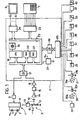
- the communication and signalling system envisages the installation in a plurality of motor vehicles of apparatus of the type shown in Figure 1.
- This apparatus comprises a signal transmitter device 1 and a signal receiver 2 coupled to an electronic processing and control unit generally indicated 3.
- an electronic processing and control unit generally indicated 3.
- To this unit is also connected a plurality of sensor or detector devices generally indicated 4 intended to provide the unit 3 with electrical signals indicative of travelling conditions of the motor vehicle.
- a control keyboard and visual display device indicated 5 and 6 respectively are installed in the passenger compartment of the motor vehicle and connected to the processing and control unit 3.
- the transmitter device 1 and the receiver 2 are intended to be mounted for example on the roof of the motor vehicle or in the external rear view mirror thereof, in order to transmit/receive signals to/from corresponding devices installed in motor vehicles travelling in the opposite direction.
- the transmitter device 1 is an infra-red transmitter and includes in known manner a plurality of infra-red light emitting diodes 7 controlled by a power circuit 8 which in turn is controlled by the control and processing unit 3 through a driver circuit 9.
- the receiver 2 comprises at least one infra-red sensing diode 10, for example a PIN diode, disposed in series with a resistor 11 and a polarising circuit 12 of known type between a d.c. voltage supply V. and earth.
- the anode of the diode 10 is coupled through a capacitor 13 with an amplifier 14 the output of which is connected to a band pass filter 15. The output of the latter is coupled to the input of a further amplifier 16.
- transmitter and receiver devices could be used instead of the transmitter and receiver devices illustrated, for example an ultrasonic transmitter and receiver or a radio transmitter and receiver.
- the electronic processing and control unit 3 in- dudes a CPU 18 provided with a clock signal generator (clock) 19, random access memory (RAM) circuits 20 and read-only memory devices (ROM) 21.
- clock clock signal generator
- RAM random access memory
- ROM read-only memory devices
- the unit 3 includes a bus 22 for the data and the addresses to which the CPU 18 and the memories 20, 21 are connected. This bus is also connected through a first input/output gate 17, to the output of the amplifier 16 and the input of the pilot circuit 9.
- the bus 22 is also connected to a keyboard scanner 23 and a pilot device 24 of the signalling device 6.
- the latter may be constituted, for example, by a liquid crystal or light emitting diode display, by a cathode ray tube and/or possibly by a voice synthesizer.
- the sensor and detector devices 4 are connected to a signal interface and conditioning circuit 25 which in turn is connected to the bus 22 through a further input/output gate 26.
- the processing and control unit 3 also includes a stabilised supply 27 connected between a d.c. voltage supply V and earth, for providing at its output a stablilised voltage Vcc for the devices of the unit 3.
- the group of sensor and detector devices 4 includes:
- the processing and control unit 3 is arranged by entirety conventional programming techniques to assume automatically three possible modes of operation, which will be described in detail below, in dependence on the signals provided by the detector devices 4 and the signals picked up by the receiver device 2.
- the processing and control unit 3 analyses cyclically the signals supplied to it by the sensors and detectors 4.
- the processing and control unit 3 assumes automatically a first mode of operation and activates the transmitter device 1 automatically, causing the radiation of signals of a first type containing information indicative of the travelling condition detected.
- the travelling condition in which the motor vehicle is made to effect a forced stop may be identified automatically when the sensor 31 indicates that the engine of the motor vehicle is running and the signals provided by the sensor 30 indicate that the average speed of the motor vehicle has been kept between two predetermined values, for example between one and ten km/h for the last x minutes ( for example 15 minutes).
- the processing and control unit 3 counts the number of times the motor vehicle stops with the engine running (information obtainable from the signals provided by the sensors 30 and 31) and decides that there is a tailback when the number of such stops counted in a predetermined time interval (for example 15 minutes) is greater than a predetermined number (for example 5 stops).
- the travelling condition of free traffic flow may be identified in the following manner: the signals provided by the speed sensor 30 in the last y minutes (for example 15 minutes) indicate that the speed of the motor vehicle has been kept constantly above a predetermined threshold value (for example 70 km/h) in this interval.
- a predetermined threshold value for example 70 km/h
- processing and control unit 3 may be arranged to analyse the signals provided by the detector sensors 4 and the recognition of the travelling conditions are a simple matter of programming which does not present any problems for an expert.
- Data indicative of respective signal messages are stored in the read only memory devices 21, corresponding to each of the predetermined travelling conditions recognisable by the processing and control unit 3.
- the processing and control unit 3 causes the transmission by the transmitter device 1 of coded signals indicative of the message relative to the travelling condition detected.
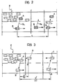
- FIG 2 is a plan view from above of a section of road with two carriageways; in the left hand part of the upper carriageway a "tailback" Z of motor vehicles proceeds slowly towards the left, effecting frequent stops and starts.
- a motor vehicle A has apparatus of the type shown in Figure 1: the processing and control unit 3 of this apparatus identifies the tailback travelling condition, and causes the transmission ofsignals of a first type Si containing information indicative of the travelling condition towards the other carriageway.
- the motor vehicle A will be said to act as a"pilot" or "primary source”.
- the signals transmitted by the transmitter device 1 of the latter are picked up by the receiver device 2 and analysed by the processing and control unit 3 of B.
- the processing and control unit 3 of the motor vehicle B is thus disposed to act in a second mode of operation, and activates the transmitter device 1 connected to it thus, causing the transmission of signals of a second type S 2 towards the other carriageway.
- the information content of the signals S 2 contains at least part of the information content of the signals S 1 transmitted by the motor vehicle A and in particular contains the information indicative of the travelling condition detected by A, that is, in the present example, the information indicative of the tailback travelling condition.
- the motor vehicle B acts as a "messenger”, that is, substantially as a “repeater” or secondary source.
- a further motor vehicle C also equipped with apparatus of the type shown in Figure 1, passes close to the motor vehicle B in the carriageway in which A as travelling, the receiver device 2 of C picks up the signals transmitted by the transmitter device 1 of B. Consequently its processing and control unit 3 automatically decodes the signals received and causes the presentation to the driver of C,through the signalling device 6,of a message indicative of the travelling condition detected by A on the same carriageway as that in which C is travelling.
- the motor vehicle C acts as an information "receiver". The information thus received may allow the driver of C to choose an alternative route in order to avoid joining the tailback in which vehicle A has become involved.
- the unit 3 activates the signalling devices 6. This may occur even simultaneously with the transmission signals of the first or second type, that is even during operation as a "pilot” or “messenger”.
- the processing and control unit 3 is arranged to stop the transmission of signals of the first type (in operation as a "pilot") or of the signals of the second type (in operation as a "messenger") when the signals provided by the steering sensor 34 indicate that the motor vehicle has negotiated a turn having a radius of curvature less than a predetermined value.
- processing and control unit 3 may also be arranged to change automatically from the first mode of operation to the second mode of operation when the receiver device 2 connected thereto picks up signals of the said first type.
- the processing and control unit 3 may also be arranged to change automatically from the first mode of operation to the second mode of operation when the receiver device 2 connected thereto picks up signals of the said first type.
- FIG 3 illustrates in greater detail the same situation of operation of the system according to the invention as that shown in Figure 2.
- the motor vehicle A proceeding towards the left encounters a tailback Z of motor vehicles which are stationary or moving slowly, when it is in the position indicated in broken outline.
- the tailback situation having been recognised in the manner explained above, the control and processing unit 3 of the motor vehicle A initiates the transmission of signals of the first type, signalling the tailback travelling condition in the upper carriageway.
- the CPU 18 initiates a computation of the time elapsed from the moment of detection of the tailback travelling condition.
- the motor vehicles Z and A continue slowly with frequent stops and starts until, when the vehicle A is in the position illustrated in full outline, a motor vehicle B provided with apparatus according to Figure 1 passes adjacent A and picks up the signals transmitted thereby. At this instant a time interval t has elapsed and the vehicle A has travelled a distance d since the moment at which the unit of this motor vehicle detected the tailback travelling condition.
- the processing and control unit 3 of the apparatus shown in Figure 1 is also arranged, by entirely conventional programming techniques, to compute, in the first mode of operation, the time elapsed and the distance travelled since the detection of one of the said travelling conditions.
- the computation of the time elapsed can easily be carried out on the basis of the signals provided by the clock pulse generator 19 while the computation of the distance travelled may be effected instantaneously from the signals provided by the odometer 32.
- the CPU 18 may thus easily be programmed so that in the first mode of operation it causes the transmission of signals of the first type including a recurring information content indicative of the travelling condition detected and a periodically updatable information content, indicative of the distance travelled and/or the time elapsed since the detection of the said travelling condition.
- the signals of the first type picked up by the receiver of the motor vehicle B include an information content indicative of the tailback travelling condition and an updated information content indicative of the distance d and the time t.
- the processing and control unit 3 may also easily be arranged to compute periodically, in the second mode of operation, the time elapsed and the distance travelled by the motor vehicle since the receipt of signals of the first type and to transmit periodically, by means of the transmitter device 1, signals of the second type also including a recurring content substantially corresponding to the recurring content of the signals of the first type picked up, and a periodically updated information content indicative of the distance travelled and/or the time elapsed from the receipt of the signals of the first type.
- the processing and control unit 3 of the apparatus of the vehicle B which has received and recognised the signals transmitted by the vehicle A starts up computation of the time t' elapsed and the distance d' travelled from the moment at which it picked up the signals of the first type ( Figure 3).
- the processing unit 3 in the second mode of operation, at the instant of receipt of the signals of the first type,starts automatically the transmission of signals of the second type the periodically updated information content whereof is indicative of the time t' elapsed since the reception of the signals of the first type S i picked up, the time of stoppage t indicated in the signals of the first type picked up, and the distance d' travelled by the motor vehicle since the receipt of the signals of the first type less the distance d indicated in the signals of the first type received.
- the processing and control unit 3 may be arranged to "recognise" (on the basis of signals provided by the detector devices 4) further travelling conditions, and in particular conditions affecting both directions of travel on a given roadway on which a vehicle is travelling such as, for example, snow or rain or fog banks.
- the condition of travelling in rain is identified on the basis of the signal provided by the sensor 35 for sensing the activation of the windscreen wiper devices.
- the condition of travelling in a fog bank may for example be identified by analysis of the signals provided by the speed sensor 30 and .by the sensor 36 for detecting the activation of the rear fog lights; if these lights are activated and if the speed of the motor vehicle remains below a predetermined value (for example 40 km/h) for a predetermined period of time (for example 30 seconds) the processing and control unit 3 deduces that the motor vehicle is travelling in a fog bank.
- a predetermined value for example 40 km/h
- a predetermined period of time for example 30 seconds
- the unit 3 of a motor vehicle recognises the occurrence of one of the said travelling conditions it causes the transmission of signals of the first type indicative both of the condition recognised and of the fact that this condition belongs to the said group of further travelling conditions.
- the unit 3 of the latter motor vehicle assumes a further mode of operation and activates the signalling devices 6 connected thereto to provide the driver with a signal or message corresponding to the travelling condition recognised by the unit 3 of the said first motor vehicle.
- the processing and control unit 3 of the apparatus according to Figure 1 may also easily be arranged so that in the second mode of operation, it causes the transmission of the said signals of the second type only when the receiver 2 connected thereto picks up signals of the first type having the same recurring information content for a predetermined number of times (for example two times) in a predetermined time interval.
- This device allows the probability of bogus signalling to be reduced.
- a motor vehicle B will start to transmit signals of the second type S 2 on condition that it has picked up signals of the first type S 1 with the same recurring information content, emitted by two successive motor vehicles A 1 and A 2 proceeding in the opposite direction, at least twice in a predetermined time interval (for example three minutes).
- the activation of the signalling devices 6 may be conditional upon the repeated receipt of signals of the second type (or of the first type in the said further mode of operation) with the same recurring information content.
- the processing and control unit 3 of the apparatus of the Figure 1 may be arranged to store, for example in the memory devices 20, the number of times signals of the first type having the same recurring information content are received consecutively in the second mode of operation, and to calculate and update a reliability index for the signals of the first type in dependence on the number of times they have been received and to generate and transmit signals of the second type, the periodically-updated information content whereof contains information indicative of the value of the reliability index.
- this reliability index is constituted by the actual number of times signals of the first type with the same recurring information content are received consecutively.
- the processing and control unit 3 is to advantage arranged to calculate and update a second reliability index relative to the signals of the second type received, the second index being a function of the reliability index of the corresponding signals of the first type and of the number of times signals of the second type with the same recurring information content are received consecutively.
- the processing and control unit provides the driver with the reliability index of the signals of the second type received through the signalling device 6. The driver is thus provided not only with messages or indications relative to the type of travelling condition detected further downstream but also with an index of how reliable this information is.
- the signal emitted by the apparatus of Figure 1 may be a serial signal encoded by the PCM technique with the following protocol by way of example:
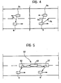
- FIG. 5 illustrates schematically a further possible application of the system according to the invention.
- a monitoring and diagnosis station generally indicated 50 is installed between the carriageways.
- This station comprises a receiver device 52 for picking up signals radiated by the transmitter device 1 installed in a motor vehicle D provided with apparatus according to Figure 1 and passing adjacent the station 50, as shown in Figure 5.
- the station 50 further includes a transmitter device 51 downstream of the receiver device 52 in the direction of advance of the motor vehicle D. This transmitter is arranged to send out signals which can be picked up by the receiver device 2 with which the motor vehicle D is provided.
- the transmitter device 51 and the receiver 52 are connected to a processing and diagnosis unit 53 the functions of which will be described below.
- the processing and control unit 3 may easily be arranged to assume a fourth mode of operation when the user imparts a predetermined manual command to it, for example by means of the keyboard 5; in this fourth mode of operation, the unit 3 activates the transmitter device 1 to transmit signals of a third type indicative of the operating conditions of the engine of the motor vehicle indicated by several of the detector sensors 4 indicated above or by further devices not illustrated and possibly connected to the processing and control unit 3. All the signals of the third type, when picked up by the transmitter device 52 of a monitoring and diagnosis station 50, are passed to the processing and diagnosis unit 53 which processes them and generates corresponding diagnosis signals containing information on the state of efficiency of the vehicle. These diagnosis signals are re-transmitted to the motor vehicle through the transmitter 51. The processing and control unit 3 in the said mode of operation activates the signalling device 6 to present the user with indications or messages corresponding to the information content of the diagnosis signals received.
Landscapes
- Physics & Mathematics (AREA)
- General Physics & Mathematics (AREA)
- Business, Economics & Management (AREA)
- Emergency Management (AREA)
- Traffic Control Systems (AREA)
- Selective Calling Equipment (AREA)
- Electric Propulsion And Braking For Vehicles (AREA)
Claims (22)
dadurch gekennzeichnet,
daß das System weiterhin folgende Teile aufweist:
daß sie automatisch
und daß sie die Signalisiermittel (6) automatisch jedesmal aktiviert, wenn die Empfangsmittel (2) Signale der zweiten Art aufnehmen, um dem Benutzer mit einem Signal oder einer Botschaft zuzuführen, die dem Informationsgehalt der Signale der zweiten Art entspricht, die von den Empfangsmitteln (2) aufgenommen wurden.
Applications Claiming Priority (2)
| Application Number | Priority Date | Filing Date | Title |
|---|---|---|---|
| IT67412/85A IT1183820B (it) | 1985-05-06 | 1985-05-06 | Sistema di comunicazione e segnalazione automatica fra una pluralita di autoveicoli |
| IT6741285 | 1985-05-06 |
Publications (2)
| Publication Number | Publication Date |
|---|---|
| EP0201461A1 EP0201461A1 (de) | 1986-12-17 |
| EP0201461B1 true EP0201461B1 (de) | 1990-01-03 |
Family
ID=11302170
Family Applications (1)
| Application Number | Title | Priority Date | Filing Date |
|---|---|---|---|
| EP86830064A Expired EP0201461B1 (de) | 1985-05-06 | 1986-03-18 | Kommunikationssystem und selbsttätige Meldung zwischen mehreren Motorfahrzeugen |
Country Status (5)
| Country | Link |
|---|---|
| US (1) | US4706086A (de) |
| EP (1) | EP0201461B1 (de) |
| JP (1) | JPH0682439B2 (de) |
| DE (1) | DE3668088D1 (de) |
| IT (1) | IT1183820B (de) |
Cited By (2)
| Publication number | Priority date | Publication date | Assignee | Title |
|---|---|---|---|---|
| DE102009034214B4 (de) * | 2008-07-25 | 2013-07-04 | GM Global Technology Operations LLC (n. d. Ges. d. Staates Delaware) | System für die Kenntnis und Diagnose von Kommunikationsmerkmalen zwischen Fahrzeugen |
| DE102006026653B4 (de) | 2005-12-13 | 2021-09-16 | Volkswagen Ag | Vorrichtung und Verfahren zum Steuern eines Fahrzeugs |
Families Citing this family (87)
| Publication number | Priority date | Publication date | Assignee | Title |
|---|---|---|---|---|
| DK604786D0 (da) * | 1986-12-16 | 1986-12-16 | Jensen Kaj Berg | Selvstyret sidespejl |
| JP2582369B2 (ja) * | 1987-05-13 | 1997-02-19 | 日本電気株式会社 | ロ−ミング登録・解除方式 |
| WO1989001424A1 (en) * | 1987-08-10 | 1989-02-23 | Milde Karl F Jr | Intelligent, automatic hazard warning system for a motor vehicle |
| US4764978A (en) * | 1987-08-20 | 1988-08-16 | Argo Eckert H | Emergency vehicle radio transmission system |
| US4916296A (en) * | 1987-10-29 | 1990-04-10 | Jerry R. Iggulden | Light modulating smart card |
| US4811379A (en) * | 1987-12-21 | 1989-03-07 | Motorola, Inc. | Speak back paging system |
| US5056152A (en) * | 1988-02-08 | 1991-10-08 | Motorola, Inc. | Dual level prioritized vehicular repeater system |
| EP0349470A3 (de) * | 1988-03-30 | 1992-07-15 | Pan-Drive S.A. | Fernleitungs- und Informationssystem für Fahrer und Fussgänger im Strassenverkehr |
| US4962457A (en) * | 1988-10-25 | 1990-10-09 | The University Of Michigan | Intelligent vehicle-highway system |
| US5142278A (en) * | 1989-04-18 | 1992-08-25 | Qualcomm Incorporated | Current carrier tractor-trailer data link |
| US5081707A (en) * | 1989-08-08 | 1992-01-14 | Motorola, Inc. | Knowledge based radio |
| ES2021500A6 (es) * | 1990-03-09 | 1991-11-01 | Alejo Trevijano Jose Javier | Aparato de intercomunicacion entre automoviles por rayos infrarrojos. |
| JPH03262099A (ja) * | 1990-03-13 | 1991-11-21 | Oki Electric Ind Co Ltd | 異常検出システム |
| CA2042133C (en) * | 1990-07-10 | 1997-09-09 | Hiroaki Kita | Equipment for transporting a load |
| DE4034681A1 (de) * | 1990-10-31 | 1992-05-14 | Norm Pacific Automat Corp | System zur uebertragung von verkehrsinformationen zwischen fahrzeugen und zur steuerung |
| US5428544A (en) * | 1990-11-05 | 1995-06-27 | Norm Pacific Automation Corporation | Traffic information inter-vehicle transference and navigation system |
| US5841367A (en) * | 1990-11-07 | 1998-11-24 | Giovanni; Caico | Electronic equipment for prevention of collisions between vehicles |
| JPH04295999A (ja) * | 1990-12-28 | 1992-10-20 | Norm Pacific Autom Corp | 車輌相互間の交通状況を告示する方法 |
| IL98498A (en) * | 1991-06-14 | 1994-01-25 | Vardi Shlomo | Electro-optical monitoring system for vehicles |
| FR2682792B1 (fr) * | 1991-10-16 | 1995-10-20 | Ii Bc Sys | Dispositif destine a eviter les carambolages en chaine. |
| SE501095C2 (sv) * | 1992-08-31 | 1994-11-14 | Carrnovo Ab | Förfarande och anordning för styrning av ett antal rullande enheter i en bananläggning |
| US5424726A (en) * | 1992-09-30 | 1995-06-13 | Intrass Company | Method, apparatus and system for transmitting and receiving data in a moving linear chain |
| DE69317266T2 (de) * | 1993-05-11 | 1998-06-25 | St Microelectronics Srl | Interaktives Verkehrsüberwachungsverfahren und -vorrichtung |
| DE4331286A1 (de) * | 1993-09-15 | 1995-03-16 | Bosch Gmbh Robert | Verfahren und Einrichtung zur bidirektionalen Übertragung von Datensignalen |
| JP3223220B2 (ja) * | 1993-10-28 | 2001-10-29 | 本田技研工業株式会社 | 車両の相互通信装置 |
| US5572201A (en) * | 1994-08-05 | 1996-11-05 | Federal Signal Corporation | Alerting device and system for abnormal situations |
| US5699056A (en) * | 1994-12-28 | 1997-12-16 | Omron Corporation | Traffic information system |
| JP3191621B2 (ja) * | 1995-03-14 | 2001-07-23 | トヨタ自動車株式会社 | 車両走行誘導システム |
| JP3358403B2 (ja) * | 1995-09-11 | 2002-12-16 | トヨタ自動車株式会社 | 隊列走行制御装置 |
| US5771484A (en) * | 1996-02-28 | 1998-06-23 | Sun Microsystems, Inc. | Automated positive control traffic system for weather |
| US5917433A (en) * | 1996-06-26 | 1999-06-29 | Orbital Sciences Corporation | Asset monitoring system and associated method |
| US5900825A (en) * | 1996-08-01 | 1999-05-04 | Manitto Technologies, Inc. | System and method for communicating location and direction specific information to a vehicle |
| DE19707537A1 (de) * | 1997-02-25 | 1998-08-27 | Alsthom Cge Alcatel | Verfahren zur Weitergabe von Informationen zwischen beweglichen Körpern und Kommunikationseinrichtung zur Durchführung des Verfahrens |
| DE19730792A1 (de) * | 1997-07-18 | 1999-01-21 | Bosch Gmbh Robert | Verfahren und Telematikgerät zur Ermittlung von Verkehrsinformationen |
| DE19730791A1 (de) * | 1997-07-18 | 1999-01-21 | Bosch Gmbh Robert | Verfahren zur Erstellung von Warnhinweisen für Fahrer eines Kraftfahrzeugs und Verkehrswarngerät |
| EP0908862A3 (de) * | 1997-10-10 | 2000-08-16 | Miltronik GmbH & Co. KG | Schnittstelleneinrichtung zwischen einem Fahrzeug und einer Auswerteeinrichtung |
| DE19750942A1 (de) * | 1997-11-17 | 1999-05-20 | Delphi 2 Creative Tech Gmbh | Verfahren und Vorrichtung zum Signalisieren von lokalen Verkehrsstörungen |
| DE19758155A1 (de) * | 1997-12-30 | 1999-07-01 | Bosch Gmbh Robert | Einrichtung zur Warnung des Fahrers eines Kraftfahrzeugs |
| US6054831A (en) * | 1998-03-24 | 2000-04-25 | Zebco Corporation | Radio frequency remote control for trolling motors |
| US6011492A (en) * | 1998-06-30 | 2000-01-04 | Garesche; Carl E. | Vehicle warning system for visual communication of hazardous traffic conditions |
| JP3495258B2 (ja) * | 1998-07-09 | 2004-02-09 | 三菱電機株式会社 | 交通情報提供装置 |
| US6351709B2 (en) * | 1998-12-02 | 2002-02-26 | Lear Automotive Dearborn, Inc. | Vehicle navigation system with route updating feature |
| US6121896A (en) * | 1999-01-26 | 2000-09-19 | Rahman; Anis | Motor vehicle early warning system |
| US6304816B1 (en) | 1999-01-28 | 2001-10-16 | International Business Machines Corporation | Method and apparatus for automatic traffic conditions data collection using a distributed automotive computing system |
| DE19903909A1 (de) * | 1999-02-01 | 2000-08-03 | Delphi 2 Creative Tech Gmbh | Verfahren und Vorrichtung zur Gewinnung von relevanter Verkehrsinformation und zur dynamischen Routenoptimierung |
| DE19909276B4 (de) * | 1999-03-03 | 2011-01-13 | Robert Bosch Gmbh | Verfahren und Einrichtung zur Warnung vor Staus und zur Übertragung von Nachrichten zwischen Fahrzeugen |
| US6822580B2 (en) * | 1999-05-07 | 2004-11-23 | Jimmie L. Ewing | Emergency vehicle warning system |
| JP3565413B2 (ja) * | 1999-06-16 | 2004-09-15 | 本田技研工業株式会社 | 移動体通信装置 |
| DE10007573C1 (de) * | 2000-02-18 | 2001-09-27 | Daimler Chrysler Ag | Vorrichtung zur funkbasierten Gefahrenwarnung des Fahrers eines Kraftfahrzeugs |
| US6816881B1 (en) * | 2000-03-13 | 2004-11-09 | International Business Machines Corporation | Method and apparatus for inter-application communication in wireless networks |
| DE10020958A1 (de) * | 2000-04-28 | 2001-10-31 | Valeo Schalter & Sensoren Gmbh | Einparkhilfe mit Temperaturkompensation |
| US6765495B1 (en) | 2000-06-07 | 2004-07-20 | Hrl Laboratories, Llc | Inter vehicle communication system |
| DE10041099C2 (de) * | 2000-08-22 | 2002-10-24 | Bosch Gmbh Robert | Verfahren zur Übertragung von Datenpaketen zwischen Kraftfahrzeugen |
| ATE321324T1 (de) * | 2001-05-31 | 2006-04-15 | Siemens Ag | Verfahren zum austausch von statusinformationen über direkte funkverbindungen zwischen teilnehmer-endgeräten |
| US6650252B2 (en) | 2001-08-28 | 2003-11-18 | Delphi Technologies, Inc. | Vehicle warning system and method |
| ES2185501B1 (es) * | 2001-09-27 | 2004-09-01 | Comercializacion Taisa , S.L. | Sistema para el control de vehiculos en circulacion. |
| US6942800B2 (en) * | 2001-11-19 | 2005-09-13 | Michael J. Jungbauer | Septic system treatment process |
| US20030120826A1 (en) * | 2001-12-20 | 2003-06-26 | Amir Shay | System and method for building a communication platform for the telematics domain using a distribution of network objects |
| US6609057B2 (en) | 2002-01-23 | 2003-08-19 | Ford Global Technologies, Llc | Method and apparatus for activating a crash countermeasure using a transponder having various modes of operation |
| US6480102B1 (en) | 2002-01-23 | 2002-11-12 | Ford Global Technologies, Inc. | Method and apparatus for activating a crash countermeasure in response to the road condition |
| US20030139881A1 (en) * | 2002-01-24 | 2003-07-24 | Ford Global Technologies, Inc. | Method and apparatus for activating a crash countermeasure |
| US6721632B2 (en) * | 2002-02-05 | 2004-04-13 | International Business Machines Corporation | Wireless exchange between vehicle-borne communications systems |
| US6502034B1 (en) | 2002-02-21 | 2002-12-31 | Ford Global Technologies, Inc. | Method and apparatus for activating a crash countermeasure using a transponder and adaptive cruise control |
| WO2003077223A1 (en) * | 2002-03-07 | 2003-09-18 | Taylor Lance G | Intelligent selectively-targeted communications systems and methods |
| JP2004013401A (ja) * | 2002-06-05 | 2004-01-15 | Sony Corp | 車両用通信システム、車両、および車両用通信装置 |
| JP4066777B2 (ja) * | 2002-10-21 | 2008-03-26 | 日産自動車株式会社 | 緊急通報装置 |
| US7098781B2 (en) * | 2002-11-19 | 2006-08-29 | Ho Ling Wu | Vehicle braking alert system |
| EP1422679A1 (de) * | 2002-11-19 | 2004-05-26 | Thierry Racine | System zur Verhütung von Unfällen |
| US9818136B1 (en) | 2003-02-05 | 2017-11-14 | Steven M. Hoffberg | System and method for determining contingent relevance |
| JP4255007B2 (ja) * | 2003-04-11 | 2009-04-15 | 株式会社ザナヴィ・インフォマティクス | ナビゲーション装置、およびその旅行時間算出方法 |
| JP2004348430A (ja) * | 2003-05-22 | 2004-12-09 | Pioneer Electronic Corp | 急ブレーキ車両警告装置、急ブレーキ情報送信装置、サーバ装置、急ブレーキ警告システム及び方法等 |
| GB0318480D0 (en) * | 2003-08-07 | 2003-09-10 | Koninkl Philips Electronics Nv | Method of and system for assessing the nature of movement of articles along a path of movement |
| KR100515952B1 (ko) * | 2003-09-22 | 2005-09-23 | (주) 에이티엔 | 차량간 직접통신을 이용한 교통 정보교환 방식 |
| US7188025B2 (en) | 2003-12-18 | 2007-03-06 | International Business Machines Corporation | Method and apparatus for exchanging traffic condition information using peer to peer networking |
| US8606516B2 (en) * | 2004-11-30 | 2013-12-10 | Dash Navigation, Inc. | User interface system and method for a vehicle navigation device |
| US20060164221A1 (en) * | 2005-01-18 | 2006-07-27 | Jensen John M | Sensor-activated controlled safety or warning light mounted on or facing toward rear of vehicle |
| WO2006113716A2 (en) * | 2005-04-19 | 2006-10-26 | Neomedia Technologies, Inc. | System and method for exchange of information amongst peers in a peer to peer wireless network |
| US8874477B2 (en) | 2005-10-04 | 2014-10-28 | Steven Mark Hoffberg | Multifactorial optimization system and method |
| US7427929B2 (en) * | 2005-10-12 | 2008-09-23 | Toyota Motor Engineering & Manufacturing North America, Inc. | Method and apparatus for previewing conditions on a highway |
| US20070096892A1 (en) * | 2005-10-31 | 2007-05-03 | Lear Corporation | Method and system of alerting hazards |
| DE102006005021B4 (de) * | 2006-02-03 | 2009-12-17 | Audi Ag | Verfahren zum Anzeigen einer Gefahrenstelle an oder auf einer Fahrbahn, sowie Einrichtung zum Erzeugen, Kommunizieren und Verarbeiten einer Gefahrenstelleninformation zwischen einem ersten und einem zweiten Kraftfahrzeug |
| DE102007056354A1 (de) * | 2007-11-16 | 2009-05-20 | Bayerische Motoren Werke Aktiengesellschaft | Datenaustausch zwischen zwei oder mehr Fahrzeugen, denen eine Identifikationsinformation zugeordnet ist |
| JP4893676B2 (ja) * | 2008-03-25 | 2012-03-07 | アイシン・エィ・ダブリュ株式会社 | 運転支援システム、運転支援方法及びコンピュータプログラム |
| DE102009019075A1 (de) * | 2009-04-27 | 2010-10-28 | GM Global Technology Operations, Inc., Detroit | Kraftfahrzeug mit einem Steuergerät und einer Empfangseinrichtung sowie Verfahren zur Steuerung verschiedener Funktionen eines Kraftfahrzeugs |
| US9311812B2 (en) * | 2012-03-16 | 2016-04-12 | Favepc Inc. | Transmitter and transceiver having the same in an RFID system |
| KR20150070801A (ko) * | 2013-12-17 | 2015-06-25 | 현대자동차주식회사 | 차량간 통신을 이용한 교통정보 전달방법 |
| DE102021204925A1 (de) | 2021-05-17 | 2022-11-17 | Volkswagen Aktiengesellschaft | Verfahren zum Übermitteln einer Stauwarnung und Fahrzeug |
Family Cites Families (10)
| Publication number | Priority date | Publication date | Assignee | Title |
|---|---|---|---|---|
| FR1539745A (fr) * | 1967-07-05 | 1968-09-20 | Système radio-électrique de signalisation de véhicules | |
| US3721955A (en) * | 1971-07-15 | 1973-03-20 | Rca Corp | Disabled vehicle signalling system |
| FR2240492A1 (en) * | 1973-08-08 | 1975-03-07 | Gendrot Andre | Vehicle accident signalling system - emitts radio signal to warn approaching vehicles |
| US3925763A (en) * | 1973-09-13 | 1975-12-09 | Romesh Tekchand Wadhwani | Security system |
| US4083003A (en) * | 1973-11-05 | 1978-04-04 | Products Of Information Technology, Inc. | Vehicle location system |
| US4354252A (en) * | 1977-09-27 | 1982-10-12 | Motorola, Inc. | Programmable digital data terminal for mobile radio transceivers |
| CA1116284A (en) * | 1979-10-09 | 1982-01-12 | George S. Sagi | Apparatus and system for wireless reception and transmission of coded audio and/or sonic alarm signals |
| US4455551A (en) * | 1980-01-08 | 1984-06-19 | Lemelson Jerome H | Synthetic speech communicating system and method |
| US4449114A (en) * | 1980-03-27 | 1984-05-15 | Dataspeed, Inc. | System for identifying and displaying data transmitted by way of unique identifying frequencies from multiple vehicles |
| DE3148370A1 (de) * | 1981-12-07 | 1983-06-16 | Elefterios 8079 Tauberfeld Paparizos | System zur uebertragung von informationen zwischen fahrzeugen |
-
1985
- 1985-05-06 IT IT67412/85A patent/IT1183820B/it active
-
1986
- 1986-03-18 DE DE8686830064T patent/DE3668088D1/de not_active Expired - Fee Related
- 1986-03-18 EP EP86830064A patent/EP0201461B1/de not_active Expired
- 1986-04-23 JP JP61095825A patent/JPH0682439B2/ja not_active Expired - Lifetime
- 1986-05-02 US US06/858,770 patent/US4706086A/en not_active Expired - Fee Related
Cited By (2)
| Publication number | Priority date | Publication date | Assignee | Title |
|---|---|---|---|---|
| DE102006026653B4 (de) | 2005-12-13 | 2021-09-16 | Volkswagen Ag | Vorrichtung und Verfahren zum Steuern eines Fahrzeugs |
| DE102009034214B4 (de) * | 2008-07-25 | 2013-07-04 | GM Global Technology Operations LLC (n. d. Ges. d. Staates Delaware) | System für die Kenntnis und Diagnose von Kommunikationsmerkmalen zwischen Fahrzeugen |
Also Published As
| Publication number | Publication date |
|---|---|
| IT8567412A1 (it) | 1986-11-06 |
| US4706086A (en) | 1987-11-10 |
| JPS61256500A (ja) | 1986-11-14 |
| IT1183820B (it) | 1987-10-22 |
| DE3668088D1 (de) | 1990-02-08 |
| EP0201461A1 (de) | 1986-12-17 |
| IT8567412A0 (it) | 1985-05-06 |
| JPH0682439B2 (ja) | 1994-10-19 |
Similar Documents
| Publication | Publication Date | Title |
|---|---|---|
| EP0201461B1 (de) | Kommunikationssystem und selbsttätige Meldung zwischen mehreren Motorfahrzeugen | |
| US5270708A (en) | Accident information providing system for automotive vehicle | |
| US5424726A (en) | Method, apparatus and system for transmitting and receiving data in a moving linear chain | |
| US6369720B1 (en) | Method for information transmission of vehicle data and traffic information system | |
| US6008741A (en) | Intersection information supply apparatus | |
| US6356189B1 (en) | Lighting control apparatus for automatic following travel system | |
| JPH06325290A (ja) | 自動車交通の情報伝達装置 | |
| JPH1173595A (ja) | 交通情報を形成する方法および車両用テレマティーク装置 | |
| JP3150644B2 (ja) | Vics車載光ビーコン装置のデータ出力装置 | |
| JPH10114251A (ja) | 追突防止装置 | |
| GB2222710A (en) | Vehicle monitoring systems | |
| US6510378B2 (en) | Traffic control system for signalling timely any obstruction on the road | |
| US20060229812A1 (en) | Device radio-based danger warning | |
| US11217093B2 (en) | Electronic communication device, related monitoring apparatus, supervision installation, communication method and computer program | |
| EP1022189A1 (de) | Vorrichtung zum automatischen ein und ausschalten der scheinwerfer eines fahrzeuges und für verkehrlichte | |
| FI112717B (fi) | Elektroniikkalaitteisto ajoneuvojen yhteentörmäysten estämiseksi | |
| GB2254509A (en) | Safety device for a vehicle | |
| CN1163442A (zh) | 自动监测前车安全车况的报警系统 | |
| US20030011471A1 (en) | Motion sensing apparatus having a control module and a slave module | |
| FR2649492A1 (fr) | Dispositif de securite embarque destine a eviter les accidents de circulation en chaine | |
| JP2001319295A (ja) | 光ビーコン装置および光ビーコンシステム | |
| KR100187852B1 (ko) | 탄넬에서의 자동 와이퍼 및 헤드램프 제어 시스템 및 그 제어방 법 | |
| CN215730202U (zh) | 高速公路服务区智能管理系统 | |
| JP2006044447A (ja) | 警告灯制御装置及び方法 | |
| JPH06180795A (ja) | 交通情報の表示制御方法 |
Legal Events
| Date | Code | Title | Description |
|---|---|---|---|
| PUAI | Public reference made under article 153(3) epc to a published international application that has entered the european phase |
Free format text: ORIGINAL CODE: 0009012 |
|
| AK | Designated contracting states |
Kind code of ref document: A1 Designated state(s): DE FR GB SE |
|
| PUAB | Information related to the publication of an a document modified or deleted |
Free format text: ORIGINAL CODE: 0009199EPPU |
|
| PUAF | Information related to the publication of a search report (a3 document) modified or deleted |
Free format text: ORIGINAL CODE: 0009199SEPU |
|
| 17P | Request for examination filed |
Effective date: 19861020 |
|
| R17D | Deferred search report published (corrected) |
Effective date: 19861217 |
|
| RA1 | Application published (corrected) |
Date of ref document: 19861217 Kind code of ref document: A1 |
|
| 17Q | First examination report despatched |
Effective date: 19880923 |
|
| GRAA | (expected) grant |
Free format text: ORIGINAL CODE: 0009210 |
|
| AK | Designated contracting states |
Kind code of ref document: B1 Designated state(s): DE FR GB SE |
|
| REF | Corresponds to: |
Ref document number: 3668088 Country of ref document: DE Date of ref document: 19900208 |
|
| ET | Fr: translation filed | ||
| PLBE | No opposition filed within time limit |
Free format text: ORIGINAL CODE: 0009261 |
|
| STAA | Information on the status of an ep patent application or granted ep patent |
Free format text: STATUS: NO OPPOSITION FILED WITHIN TIME LIMIT |
|
| 26N | No opposition filed | ||
| EAL | Se: european patent in force in sweden |
Ref document number: 86830064.1 |
|
| PGFP | Annual fee paid to national office [announced via postgrant information from national office to epo] |
Ref country code: GB Payment date: 19960216 Year of fee payment: 11 |
|
| PGFP | Annual fee paid to national office [announced via postgrant information from national office to epo] |
Ref country code: SE Payment date: 19960220 Year of fee payment: 11 |
|
| PGFP | Annual fee paid to national office [announced via postgrant information from national office to epo] |
Ref country code: DE Payment date: 19960227 Year of fee payment: 11 |
|
| PGFP | Annual fee paid to national office [announced via postgrant information from national office to epo] |
Ref country code: FR Payment date: 19960329 Year of fee payment: 11 |
|
| PG25 | Lapsed in a contracting state [announced via postgrant information from national office to epo] |
Ref country code: GB Effective date: 19970318 |
|
| PG25 | Lapsed in a contracting state [announced via postgrant information from national office to epo] |
Ref country code: SE Effective date: 19970319 |
|
| GBPC | Gb: european patent ceased through non-payment of renewal fee |
Effective date: 19970318 |
|
| PG25 | Lapsed in a contracting state [announced via postgrant information from national office to epo] |
Ref country code: FR Free format text: LAPSE BECAUSE OF NON-PAYMENT OF DUE FEES Effective date: 19971128 |
|
| PG25 | Lapsed in a contracting state [announced via postgrant information from national office to epo] |
Ref country code: DE Effective date: 19971202 |
|
| EUG | Se: european patent has lapsed |
Ref document number: 86830064.1 |
|
| REG | Reference to a national code |
Ref country code: FR Ref legal event code: ST |